Ricmotech AP-Xtreme User manual

Page B-1
Revised: 3/9/2020
Last Edited by: FR
APX 1000+ Assembly Manual
AP-Xtreme
Sim-Racing Chassis
Master Assembly Guide
SECTION B: Main Chassis Assembly

Page B-2
Revised: 3/9/2020
Last Edited by: FR
APX 1000+ Assembly Manual
If you have assembled the SlipSense Assembly from Section A then skip to the next page!
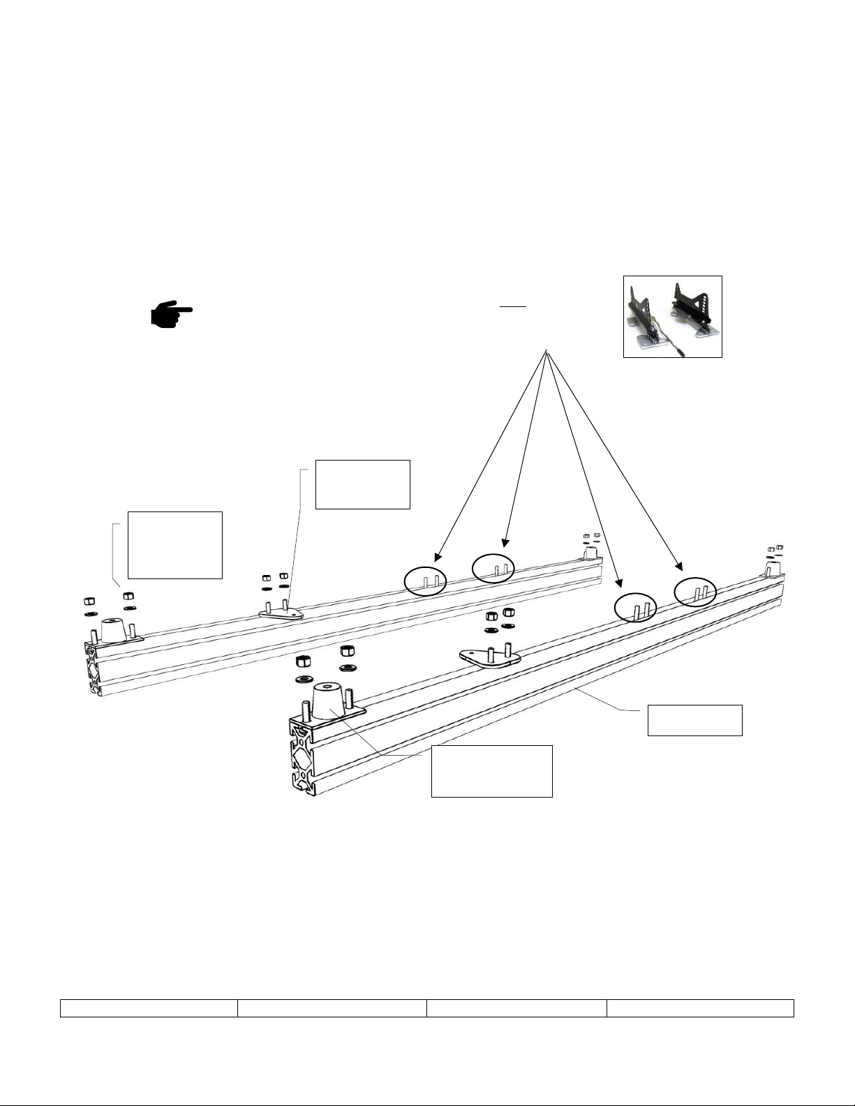
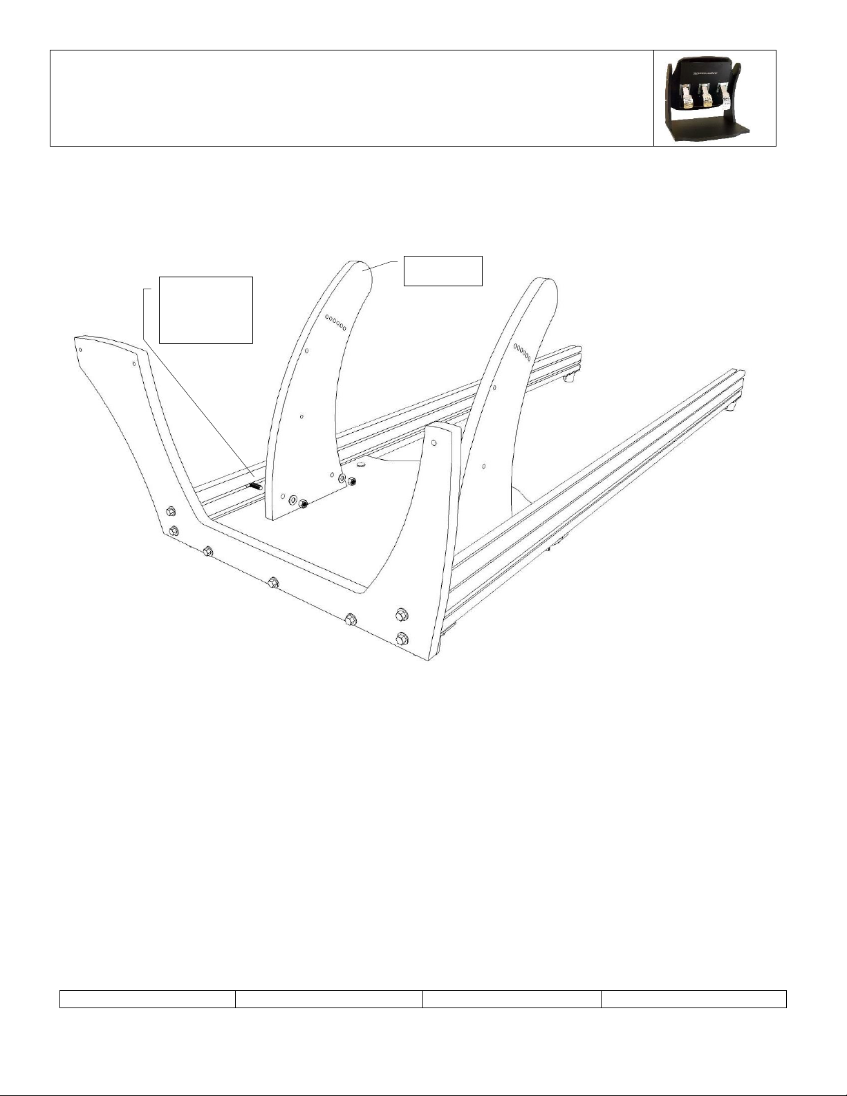
Place Rails E1 on the ground as shown. Slide 6 C2-1 carriage bolts into the slots as shown and secure each A10 vibration
foot even with each end with the indicated washer and nut. Tighten these bolts. Then loosely secure the floor brackets
about ¼ way from the front end of the rails. Do not tighten these yet.
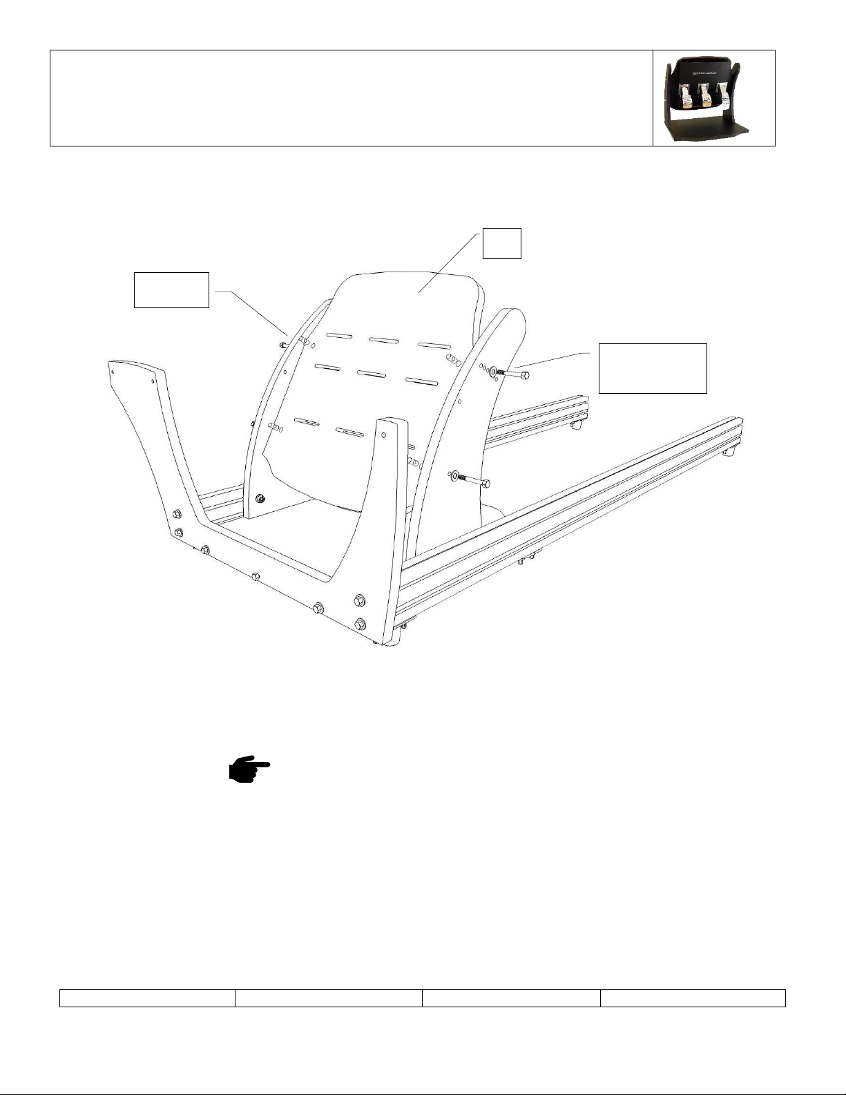
If you are installing seat sliders for a real racing seat,
please install 8 additional C2-1 Bolts into the rails here.
C2-1 x 12
W2 x 12
N2 x 12
A1 Floor
Brace x 2
A10 Vibration
Foot x 4
E1 x 2

Page B-3
Revised: 3/9/2020
Last Edited by: FR
APX 1000+ Assembly Manual
Using a ¼” (7mm) drill bit drill through the partial holes according to the pedals you are using. These holes may have
been drilled for you before it shipped. It will be easier to attach these pedals to the floor now.
Secure the B1 floor panel to the B2 front cap using the fasteners indicated. Hand-tighten these bolts. The wider side of
the front cap should go toward the shifter side. By flipping this panel around the chassis can be assembled as a left or
right-hand drive.
B1 Bottom Side
B1
B2
N3 x 3
W1 x 3
H1-3 x 3
Drill these for
GTpro3 Floor
Mount Pedals
Partially
drilled holes
to bottom.

Page B-4
Revised: 3/9/2020
Last Edited by: FR
APX 1000+ Assembly Manual
Turn the E1 rails so they stand on the rubber vibration feet. Lower the assembled floor and front cap between the rails
and secure using the indicated bolts and washers at the front. Then slide the floor brackets into alignment with the holes
on the floor and secure using the fasteners indicated. Insure all the pieces fit tight together and tighten the front and
floor bolts.
W2 x 4
H2-2 x 4
W1 x 2
N1 x 2
C1-2 x 2

Page B-5
Revised: 3/9/2020
Last Edited by: FR
APX 1000+ Assembly Manual
Refer to the pedals you will be installing and advance to the section indicated below.
If you will be installing Thrustmaster or
Logitech pedals in the inverted position
please advance to page 6.
If you will be installing GTpro3 or other floor
mounted pedals please advance to page 11.
If you will be installing GTpro1 pedals in the
inverted position please advance to page 8.
If you will be installing the dead pedal please
advance to page 9.

Page B-6
Revised: 3/9/2020
Last Edited by: FR
APX 1000+ Assembly Manual
This page only applies to the Thrustmaster/Logitech Inverted Pedal Mount
Attach the pedal arches pointing back toward the driver as shown. Slide 2 carriage bolts C2-2 into the upper inside rail
from the rear of the rail. Secure the arches with washers and nuts indicated above. Only finger tighten these bolts until
the pedal are adjusted into their final location.
B3 x 2
C2-2 x 4
W2 x 4
N2 x 4

Page B-7
Revised: 3/9/2020
Last Edited by: FR
APX 1000+ Assembly Manual
This page only applies to the Thrustmaster/Logitech Inverted Pedal Mount
Attach the pedal deck B4 to the pedal arches using the hardware indicated. Do not tighten these until the final position
has been determined.
Please advance to page 11.
B4
W1 x 4
H1-3 x 4
N3 x 4

Page B-8
Revised: 3/9/2020
Last Edited by: FR
APX 1000+ Assembly Manual
This page only applies to the GTpro1 Inverted Pedal Mount
Install B14 arched panels using hardware indicated above
Slide three specialized insets into the bottom slot of each E12 extrusion. Mount using the hardware indicated above.
Please advance to page 11.
C2-2 x 4
W2 x 4
N2 x 4v
B14 x 2
E12 x 2
H2-2 x 4
W2 x 4

Page B-9
Revised: 3/9/2020
Last Edited by: FR
APX 1000+ Assembly Manual
This page only applies to the Dead Pedal
Assemble the dead pedal to achieve the desired positioning as shown below.
Assemble the pedal as shown above.
N1 x 2
W1 x 2
H1-3 x 2
W1 x 2

Page B-10
Revised: 3/9/2020
Last Edited by: FR
APX 1000+ Assembly Manual
This page only applies to the Dead Pedal
C2-2 x 4
W2 x 4
N2 x 4v

Page B-11
Revised: 3/9/2020
Last Edited by: FR
APX 1000+ Assembly Manual
Slide C2-2 carriage bolts into each outer slot of the rails. Mount the pedal arches to the outside of the rails as shown. Do
not tighten the bolts until final positioning is determined.
C2-2 x 4
W2 x 4
N2 x 4
B5 x 2

Page B-12
Revised: 3/9/2020
Last Edited by: FR
APX 1000+ Assembly Manual
Mount the B6 wheel deck using the fasteners indicated. Do not tighten these bolts until final position is determined.
B6
W1 x 4
H1-3 x 4
N3 x 4

Page B-13
Revised: 3/9/2020
Last Edited by: FR
APX 1000+ Assembly Manual
This page only applies if installing g-Sense belt tensioners
If installing seat belts as part of the g-Sense active seat belt system, then pre-install the extra bolt shown above on each
side.
C2-4 x 2

Page B-14
Revised: 3/9/2020
Last Edited by: FR
APX 1000+ Assembly Manual
Mount the B7 rear wings using the fasteners indicated. Align them even with the back of the rails and tightened them
into place.
Mount E4 on the non-shifter side with 2 C1-2 carriage bolts and 1 H1-2 carriage bolt near the front of the chassis. Secure
to the front cap with H1-2 and W1 hex bolt and washer.
B7 x 2
C2-2 x 4
W2 x 4
N2 x 4
E4 x 1
C1-2 x 2
W1 x 2
N1 x 2
H1-2 x 1
W1 x 1

Page B-15
Revised: 3/9/2020
Last Edited by: FR
APX 1000+ Assembly Manual
Take one E2 rail and install 2 C1-2 carriage bolts toward the front and 1 C1-2 carriage bolt near the rear of the chassis.
E2 x 1
C1-2 x 3
W1 x 3
N1 x 3
H1-2 x 1
W1 x 1

Page B-16
Revised: 3/9/2020
Last Edited by: FR
APX 1000+ Assembly Manual
If you purchased the sliding rail option for a real racing seat then skip to page 18
Insert 2 C1-1 carriage bolts into the slots as shown in preparation for mounting one of the Ricmotech seats. Screw the
B13 end bracket into the end of cross-member E3.
C1-1 x 2
F1 x 2
B13
2 Tall
2 Short
E3

Page B-17
Revised: 3/9/2020
Last Edited by: FR
APX 1000+ Assembly Manual
Pre-thread the C2-2 bolts, washers and nuts onto the B13 brackets. Slide the crossmembers into the bottom slot using
the taller one for the front crossmember and the shorter one for the rear cross-member. Finger-tighten the bolts until
the seat is installed and its final position can be determined.
The triangular end pieces can be mounted in either the top or bottom slot, pointing up or pointing down and the shorter
or taller one can be mounted in the front or back to help achieve the desired seating position.
C2-2 x 8
W2 x 8
N2 x 8

Page B-18
Revised: 3/9/2020
Last Edited by: FR
APX 1000+ Assembly Manual
Mount the B8 Shifter mount on the 2 inner holes using the hardware indicated.
C1-2 x 2
W1 x 2
N1 x 2
Install B8 only if installing a
Thrustmaster or Logitech Shifter
Install B8-SQ only if installing a
Quaife PSL Sequential Shifter

Page B-19
Revised: 3/9/2020
Last Edited by: FR
APX 1000+ Assembly Manual
If you did not install B8 from the previous
step then you will need to support E2 until
the next step.
Mount the remaining E4 rail onto the bottom of the shifter mount and secure at the front with the hardware indicated.
C1-2 x 2
W1 x 2
N1 x 2
E2 x 1
H1-2 x 1
W1 x 1
Slide intwo additional C1-1 on the
inner slots of both E2 rails if
mounting a button box
Slide in two additional C1-1 if
mounting a hand brake

Page B-20
Revised: 3/9/2020
Last Edited by: FR
APX 1000+ Assembly Manual
If you will be installing an H-pattern Pro
shifter you will install B9-H instead with the
cup holder opening to the rear.
Mount the Keyboard tray underneath the E4 rails and secure with the hardware indicated.
The cup holder may be oriented to the front if no shifter is present, otherwise orient toward the back.
B9
or
B9-S
C1-2 x 4 (or 6)
W1 x 4 (or 6)
N1 x 4 (or 6)
Other manuals for AP-Xtreme
2
Table of contents
Other Ricmotech Video Gaming Accessories manuals
Popular Video Gaming Accessories manuals by other brands

Tippmann
Tippmann 98 CUSTOM PLATINUM SERIES MARKER LINE owner's manual

PlayStation
PlayStation SCEH-00448 instruction manual

All In 1 Gaming
All In 1 Gaming Phantom Sim Frame Assembly instructions

Nintendo
Nintendo GameCube Modem Adapter Instruction booklet

Avermedia
Avermedia DVD EZMaker 7 C039 quick guide

Myria
Myria MG7401 user manual