manuals.online logo
Brands
  1. Home
  2. •
  3. Brands
  4. •
  5. Ricmotech
  6. •
  7. Video Gaming Accessories
  8. •
  9. Ricmotech LC27 v3 Load Cell Ki User manual

Ricmotech LC27 v3 Load Cell Ki User manual

Ricmotech LC27 v3 Load Cell Kit Installation Guide
This product fits the Logitech G25, G27, G29, G920, and G923
brake pedal
Items Needed:
1. #1 Phillips Screwdriver
2. #2 Phillips Screwdriver
3. 2.5mm Allen Wrench (Hex Key)
4. 5mm Allen Wrench (Hex Key)
5. 10mm Wrench
6. Small Flat Screwdriver
7. Needle Nose Pliers
8. Small Diagonal Cutters
9. Cardboard Box approximately 10” x 10” x 4” (25cm x 25cm x 10cm)
Installation:
1. Begin by removing the pedal faces on the pedals you
will be working on using the 2.5mm Allen wrench (hex
key). Keep the screws together with each pedal since
they may be of different lengths.
2. Flip the pedals upside down into the cardboard box
so the pedals are hanging free and the plastic base
does not fall in.
3. If you do not have an appropriate cardboard box,
use some blocks of wood or rolled up towels to
accomplish the same support.
4. Remove the 12 black screws that secure each pedal
to the bottom cover.
5. Remove the 14 silver screws that support that
secure the cover in place. Do not forget the two screws
behind the carpet gripper.
6. Lift off the bottom cover to exposethe internals. Take
pictures to assist in reassembly later.
7. Lift out the brake pedal and lay on its side with the
wiring at the top. Remove the screw securing the
black ground wire then carefully pull off the 3 plugs,
use needle nose pliers and be careful not to tear the
wires.
8. Remove the brake pedal assembly from the housing.
Using a 10mm wrench and a 5mm Allen Key, remove
the pivot from the base that secures the lower
telescoping spring housing.
9. The upper spring housing has a 3-spoke blade
inside. This is obstructed by a white cap on the G28
and G920 pedals. Remove the white cap to expose the
3 spokes. The spring assembly has the mating slot to
fit around them.
10. Insert the spring into the housings as shown. Be
sure the curved part of the base faces upwards as
shown. The wire should exit at the base of the pedal
assembly.
Note: This is important to prevent the wire from
getting damaged when the pedals are reassembled.
Damage to the wire is not covered by warranty.
11. Compress the spring to align the square cutout in
the load cell housing with the pivot hole in the base
and insert the pivot pin. Secure the pivot pin with the
10mm nut.
12. If not already inserted, insert the load cell wires into
the corresponding positions in the terminal block by
first pushing down on the locking tab with a small
screwdriver or other small tool. While holding down the
locking tab, insert the wire in a downward angle.
Release the locking tab when the wire is fully inserted.
Skip to step 14 if the wires are already inserted.
13. Gently tug on the wires to insure they are fully
seated and will not come out. Be sure the metal jaw
on the terminal block is contacting the metal strands
of the wire.
14. Lay the pedal on the pedal housing and screw the
ground terminal tothe pedal base as shown. Then plug
the three wires onto the correspondingterminals on the
LC27-2 interface board.
Note: If the load cell kit is for use with a Thrustmaster
wheelbase then the circuit board will be missing some
electronic componentsand the connection posts will be
re-labeled.
15. Lay the pedal back into position in the housing.
Using the wire ties, strap the load cell wire to the
original pedal wiring as indicated by the circles above.
Peel off the backing on the mounting pad on the back
of the interface board and secure to the plastic base as
shown.
16. Make sure the cable exiting the housing is routed
properly through the posts.
17. Place the bottom cover backon the housing and be
sure it drops into place evenly all the way around.
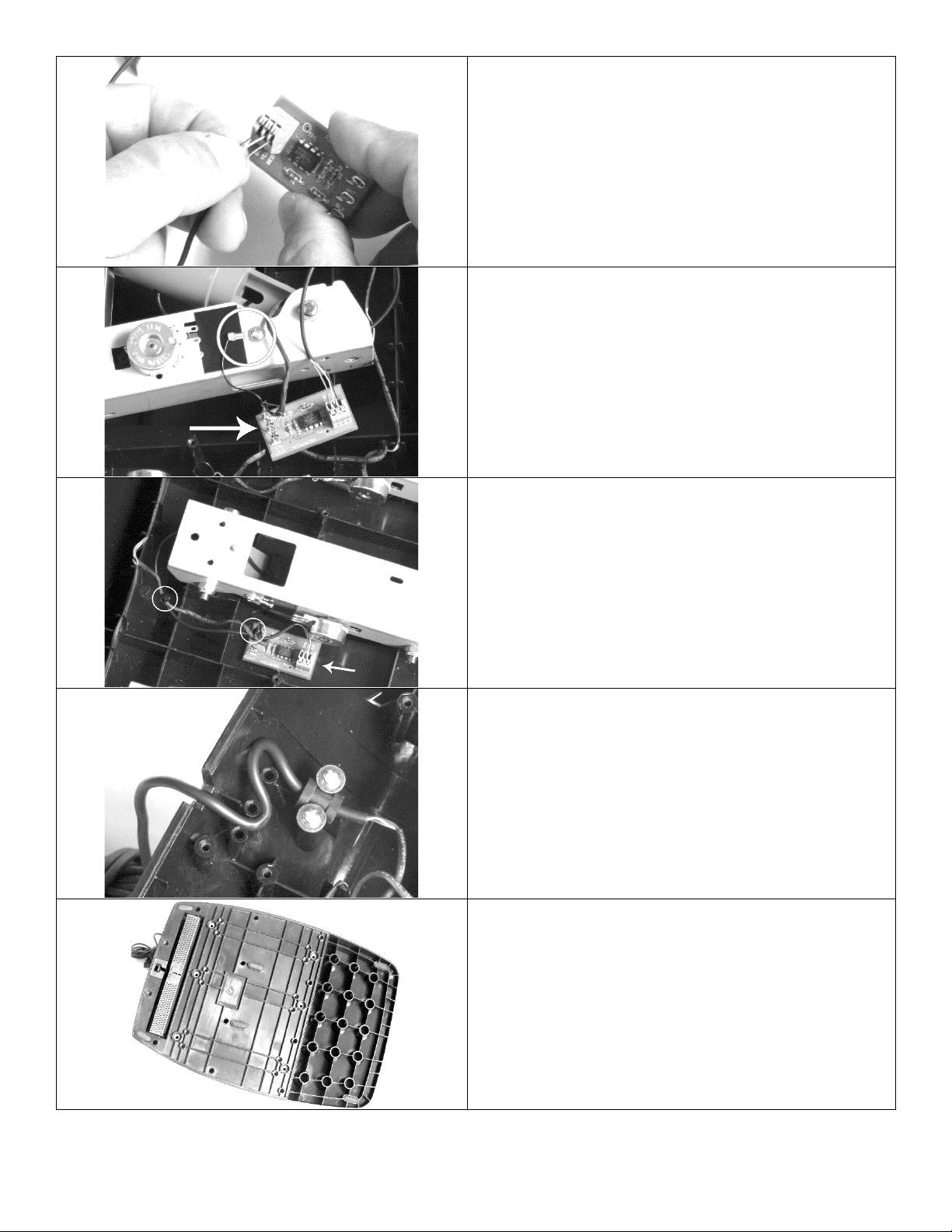
18. Ensure the cable exits the housing in the proper
place and is not pinched. If the cover does not sit
properly, remove the cover and check for obstructions.
The cover must not be forced into place.
19. Secure the cover using the original 14 silver screws
and 12 black screws removed at the beginning of the
installation. Do not forget that 2 screws go under the
carpet gripper.
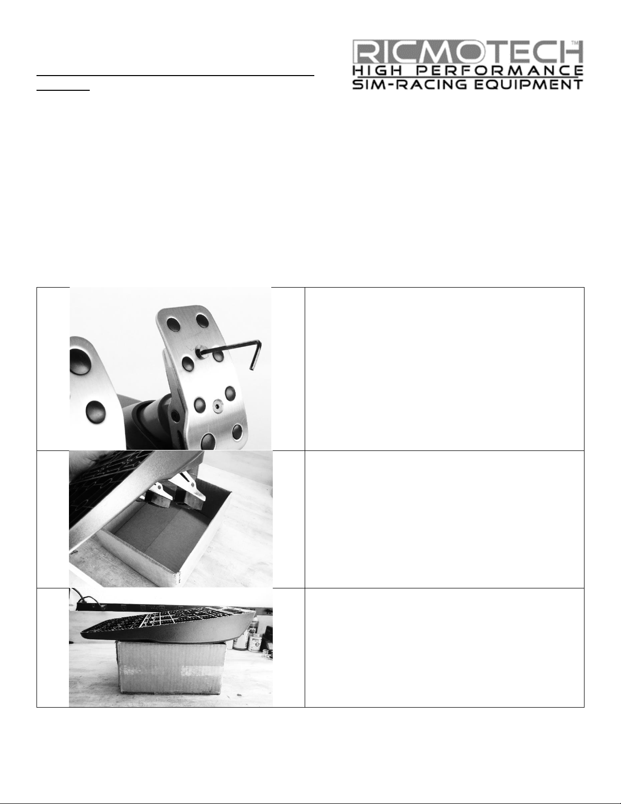
20. Reinstall the pedal faces using the original screws.
On the G27 and newer, there are different length
screws. The shorter ones are for the accelerator and
the longer ones are for the brake and clutch.
Tips for Best Performance
The pedals must be calibrated every time the wheel restarts (when it does its left to right dance). The system will learn
the maximum force used to press the pedal and that will be 100% braking in game. If at any point during the game the
pedal is pressed harder than that will become the new 100%. Therefore, we recommend pressing the pedal with
maximum force after the wheel restarts so there is no variation in braking performance during a race.
The bushing is a consumable item and will break down over time. This will change the response of the pedal. You will
gradually adapt to the change and therefore it may not be apparent. Periodically inspect the bushing and replace as
needed.
Warning: Do not stomp or beat on the brake pedal. The load cell is designed to handle several hundred pounds of force
without losing accuracy, but stomps, kicks and hammer blows can easily exceed the safe limits of the load cell. The load
cell is not warranted against failure from excessive force.
Ricmotech strongly recommends hard mounting the pedals to your sim-rig. A rigid mounting without any flex will help
you get the most out of the LC27 and give you the best improvement in your racing performance. To hard mount the
Logitech® pedals you will need 6 M6 metric bolts, their length depends the thickness of the mounting surface.
The LC27 load cell upgrade kit has been engineered to replicate the feel and reaction of a real race car brake system. To
get the most from your new load cell you should keep the following tips in mind.
Your brake will now have a soft range followed by a hard range. The soft range replicates the travel of the brake pads
before they make full contact with the brake rotors. This range will give you about 5% to 10% braking force (depending
on your final brake calibration). Use this braking range to get the weight of the car to transfer to the front wheels
without applying too much braking force.
Once the vehicle’s weight is on the front wheels you can apply more braking force without putting the car into an under-
steer condition. At this point, the brake will feel like you are pressing on a brick and will respond to how hard you press
on it. This range replicates what happens after the brake pads are in full contact with the brake rotors and there is no
further movement of the brake components.
At this point the brake pedal is near even height with the throttle pedal (G27). This facilitates proper heel-toe
downshifting since the brake is kept at the same height regardless of how much braking force you need to apply.
By keeping these principles in mind your lap times should improve by giving you better control over the vehicle’s brakes.
Work on getting your braking to be more consistent. After that happens, you will not need to brake as early because you
will not need that extra margin for error. Braking later means braking less and your lap times should then begin to
improve. Happy Racing!
Notice: Ricmotech is not responsible for any damage you may cause to your Logitech® pedals during the installation of
the LC27 load cell assembly. Installation of this load cell may void the original manufacturer’s warranty. Every LC27 is
tested for proper operation before being sent out.
Need Help?
If you run into any problems during the installation of the LC27 v3 please contact us directly at tech support at
(305) 417-9241 or via email at [email protected]om. Due to constant improvements to our products, the product
you receive may vary slightly from the product shown in the illustrations.
Copyright 2021, Ricmotech LLC. Logitech® and G25, G27, G29, G920, and G923 are trademarks of the Logitech®
corporation and the terms are used for reference purposes only. Ricmotech and the LC27 v3 load cell kit is not affiliated
with Logitech® Corporation.

Other Ricmotech Video Gaming Accessories manuals

Ricmotech AP-Xtreme User manual

Ricmotech

Ricmotech AP-Xtreme User manual

Ricmotech AP-Xtrem User manual

Ricmotech

Ricmotech AP-Xtrem User manual

Ricmotech T3PM User manual

Ricmotech

Ricmotech T3PM User manual

Ricmotech AP-Xtreme User manual

Ricmotech

Ricmotech AP-Xtreme User manual

Popular Video Gaming Accessories manuals by other brands

Myria MG7400 user manual

Myria

Myria MG7400 user manual

Konix DRAKKAR ODIN user manual

Konix

Konix DRAKKAR ODIN user manual

ACME PC user manual

ACME

ACME PC user manual

Mattel UNO TRIPLE PLAY GXV87 manual

Mattel

Mattel UNO TRIPLE PLAY GXV87 manual

Hathaway BG3142 quick guide

Hathaway

Hathaway BG3142 quick guide

FANATEC CSL quick guide

FANATEC

FANATEC CSL quick guide

ESCALADE American Legend Phazer HT600 instruction manual

ESCALADE

ESCALADE American Legend Phazer HT600 instruction manual

EXIT Toys TEMPO Soccer goal 1800 user manual

EXIT Toys

EXIT Toys TEMPO Soccer goal 1800 user manual

EastPoint NHL ATTACKER HOVER HOCKEY TABLE Assembly instructions

EastPoint

EastPoint NHL ATTACKER HOVER HOCKEY TABLE Assembly instructions

Thrustmaster RGT Force Feedback Pro user manual

Thrustmaster

Thrustmaster RGT Force Feedback Pro user manual

UNEEKOR EYE MINI user manual

UNEEKOR

UNEEKOR EYE MINI user manual

Edimensional G-Pad Pro Frequently asked questions

Edimensional

Edimensional G-Pad Pro Frequently asked questions

LumiSource Boom Chair owner's manual

LumiSource

LumiSource Boom Chair owner's manual

Thrustmaster T-CHARGE Duo NW user manual

Thrustmaster

Thrustmaster T-CHARGE Duo NW user manual

AllSportSystems MICROBAY Setup guide

AllSportSystems

AllSportSystems MICROBAY Setup guide

UCEC Video Capture All in One Pro Version manual

UCEC

UCEC Video Capture All in One Pro Version manual

Hudora 71418 INSTRUCTIONS ON ASSEMBLY AND USE

Hudora

Hudora 71418 INSTRUCTIONS ON ASSEMBLY AND USE

Mad Catz GameShark2 instruction manual

Mad Catz

Mad Catz GameShark2 instruction manual

manuals.online logo
manuals.online logoBrands
  • About & Mission
  • Contact us
  • Privacy Policy
  • Terms and Conditions

Copyright 2025 Manuals.Online. All Rights Reserved.