Ridder MotorControl RMC400 User manual

265047EN - 2019.12 - V04
Original product-manual
Ridder MotorControl RMC400
Product Manual
Lorentzstraat 32
3846 AX Harderwijk
PO Box 360
3840 AJ Harderwijk
the Netherlands
T+31 (0)341 416 854
F+31 (0)341 416 611
Iridder.com
Einfo@ridder.com
Ridder Drive Systems B.V.

TABLE OF CONTENTS
1. GUIDELINES, STANDARDS AND CONDITIONS
1.1 Applicable guidelines and standards 3
1.2 Approved personnel 3
1.3 Warning about discouraged use 3
1.4 Warranty provisions 3
2. SAFETY, PRECAUTIONS AND SYMBOLS
2.1 Signal words, instrucons and warnings 4
2.2 Precauons and safety instrucons 4
2.3 Residual risks 6
2.4 Symbols and abbreviaons 6
3. PRODUCT DETAILS
3.1 Idencaon 7
3.2 Descripon 8
3.3 Applicaon 9
3.4 Dimensions 9
3.5 Technical specicaons 9
4. INSTALL INSTRUCTIONS
4.1 Special tools and equipment 13
4.2 Installaon 13
5. CONNECT INSTRUCTIONS
5.1 Electrical material 14
5.2 Protecon - Condions and starng points 15
5.3 Overview and funcon diagram 16
5.4 Wiring diagram: Control board (RCB) 16
5.5 3-phase electric motor (208-600 VAC) 18
5.6 1-phase 3-wire electric motor (115-230 VAC) 19
5.7 1-phase 5-wire electric motor (115-230 VAC) 20
5.8 Limit switch (RSU/RLS) 20
5.9 Automac Control (ACS) (24 V AC/DC) 21
5.10 OPTIONAL - Manual Control (MC) 21
5.11 OPTIONAL - Posion Feedback (RPU) 22
5.12 OPTIONAL - Alarm (AL) 23
6. USER INSTRUCTIONS
6.1 Usage - Condions and starng points 24
6.2 Status LEDs 24
6.3 Operaon 25
6.4 Alarm 26
6.5 Safety funcons and stop funcons 26
7. COMMISSIONING INSTRUCTIONS
7.1 Commissioning - Condions and starng points 27
7.2 Check: Switching sense of the Limit Switch (RSU/RLS) 28
7.3 Check: Control direcon of the Automac Control (ACS) 29
7.4 Check: Control direcon of the Manual Control (MC) 30
8. MAINTENANCE INSTRUCTIONS
8.1 Maintenance 31
9. SERVICE
9.1 Troubleshoong 32
9.2 Blink codes 33
9.3 Technical support 34
10. ENVIRONMENT
10.1 Decommissioning and removal 34
10.2 Waste disposal 35
Ridder Drive Systems B.V.
T+31 (0)341 416 854 - F+31 (0)341 416 611 - Iridder.com
2
Ridder Drive Systems B.V.
T+31 (0)341 416 854 - F+31 (0)341 416 611 - Iridder.com
3

1. GUIDELINES, STANDARDS AND CONDITIONS
1.1 Applicable guidelines and standards
This product complies with the provisions of the European guidelines that follow:
Machinery Direcve 2006/42/EC | Low Voltage Direcve 2006/95/EC | EMC Direcve 2004/108/EC
The harmonized standards (or parts of these standards) that follow are applicable:
NEN-EN-ISO 12100:2010 | NEN-EN-IEC 60204-1 |
NEN 82079-1 (62079: 2001) | NEN5509 | ISO 3864-2
Make sure that this product is only put into operaon if the system (in which it will be installed)
complies with the provisions of the applicable standards and guidelines.
1.2 Approved personnel
This product manual contains important informaon for installers about the installaon and
commissioning of a Ridder MotorControl RMC400 control-unit. Read this product manual and
instrucons rst before the work starts. Approved mechanical and/or electrical installers, with
professional competence, must do all work safe and responsible.
TARGET GROUP FOR EACH CHAPTER CHAPTER (refer to Table of Contents)
TARGET GROUP 1 2 3 4 5 6 7 8 9 10
User (operator) • • • • (•)
Installer / Approved personnel • • • • • • • • • •
(•) = Not fully applicable
Keep this product manual with the product during the lifespan. Make sure it is available for users
(operators), installers and approved personnel.
1.3 Warning about discouraged use
The condions that follow are applicable:
• Do not change (the construcon of) the MotorControl RMC400 control-unit.
• It is not permied to use the RMC400 control-unit to li or move people.
Refer to §3.3 for a descripon of the intended use.
1.4 Warranty provisions
For the warranty period and condions refer to the ‘Condions’ secon on our website at ridder.
com, or in the Ridder catalogue.
Regulatory Conformity
Ridder Drive Systems B.V.
T+31 (0)341 416 854 - F+31 (0)341 416 611 - Iridder.com
2
Ridder Drive Systems B.V.
T+31 (0)341 416 854 - F+31 (0)341 416 611 - Iridder.com
3

2. SAFETY, PRECAUTIONS AND SYMBOLS
2.1 Signal words, instrucons and warnings
Signal words (ISO 3864-2)
This product manual contains safety instrucons with dierent signal words. The list that follows
gives the risk levels and possible eects of each signal word.
Instrucons and warnings on the product
Read the product manual to fully know all product properes,
before it is used or work starts!
Ê
It is not permied to use high-pressure cleaners (and related
cleaning agents)! Use a so brush with a small quanty of water
without cleaning agents.
Warning - Electrical voltage
2.2 Precauons and safety instrucons
Precauons
GENERAL
A system can be dangerous. Safety precauons and instrucons are important.
• If these precauons cannot be obeyed, then use warnings.
• The responsibility for precauons and warnings lies with the installer of the system. Refer to the,
local or naonal, laws and regulaons of the country if a cercaon (mark) is necessary.
• Parts of the electrical or electronic installaons are connected to dangerous electrical voltages.
Work without professional competence or not obeyed warning instrucons could cause injury
and/or material damage.
Suggeson to perform an operaon more eecve.
May result in damage or problems if an acon is performed
incorrectly.
May result in minor injury if the hazard is not avoided.
Signicant injury, possible death, if the hazard is not avoided.
Severe injury and possible death if the hazard is not avoided.
Ridder Drive Systems B.V.
T+31 (0)341 416 854 - F+31 (0)341 416 611 - Iridder.com
4
Ridder Drive Systems B.V.
T+31 (0)341 416 854 - F+31 (0)341 416 611 - Iridder.com
5

• Ridder is not responsible for injury, material damage or consequenal damage if accessories are
used that Ridder did not make.
TRANSPORT, STORAGE AND PACKAGING
The condions and instrucons that follow are applicable.
• Ambient temperature: -15 to +60 °C (+5 to +140 °F).
• Ambient: A not-condensed relave humidity is necessary.
• Do a check for transport damage and missing parts immediately on incoming goods.
• Tell damages and missing parts immediately to the transport company and to your local Aer
Sales contact person.
• Do not use damaged products and if necessary do not start the work.
• Send the product to the installaon site before it is removed from the (sealed) packaging. This
prevents damage (from mechanical shocks) to the product.
• Use applicable means-of-transport with dimensions which are sucient. Use (if necessary) the
correct work equipment and accessories. Refer to “Dimensions” and “Technical specicaons”.
Make sure that the working condions comply with the, local or naonal, laws and regulaons.
• Make sure that storage areas and the areas in the means-of-transport are dry and the airow is
sucient.
• Make sure that the products do not touch the (moist) boom surface of storage areas and of the
means-of-transport (use pallets or such). The boom surfaces must be smooth.
• Make sure that the products are protected from dust, dirt and direct sunlight.
• Apply an applicable corrosion-prevenve agent to surfaces that are not painted.
• Aer installaon discard the packaging and obey the applicable naonal and/or local regulaons.
Safety instrucons
• Use (if applicable) personal protecve-equipment for protecon which agrees with the dierent
types of work.
• Do not let persons and not approved personnel be near controls and systems in operaon.
• Damaged systems must be stopped immediately unl they are repaired.
• Use safety barriers, for system parts that move, to a height of 2.5 m from the ground.
• The safety distance to the danger zone (if applicable) must agree with ISO 13857:2008.
• Do not operate systems when persons are in the danger zone and can touch the system.
• Monitor the danger zone when you work with or near the system.
• Stop and de-energize systems during maintenance and cleaning work on or near the system.
• Make sure that there is sucient space between parts that move and adjacent objects.
• Stay away from or safety areas where there is a risk to become caught in a system that moves.
• The torque and the duty cycle of the system must be in the range of the motor gearbox
parameters. Refer to the product manual of the used Ridder motor-gearbox at ridder.com.
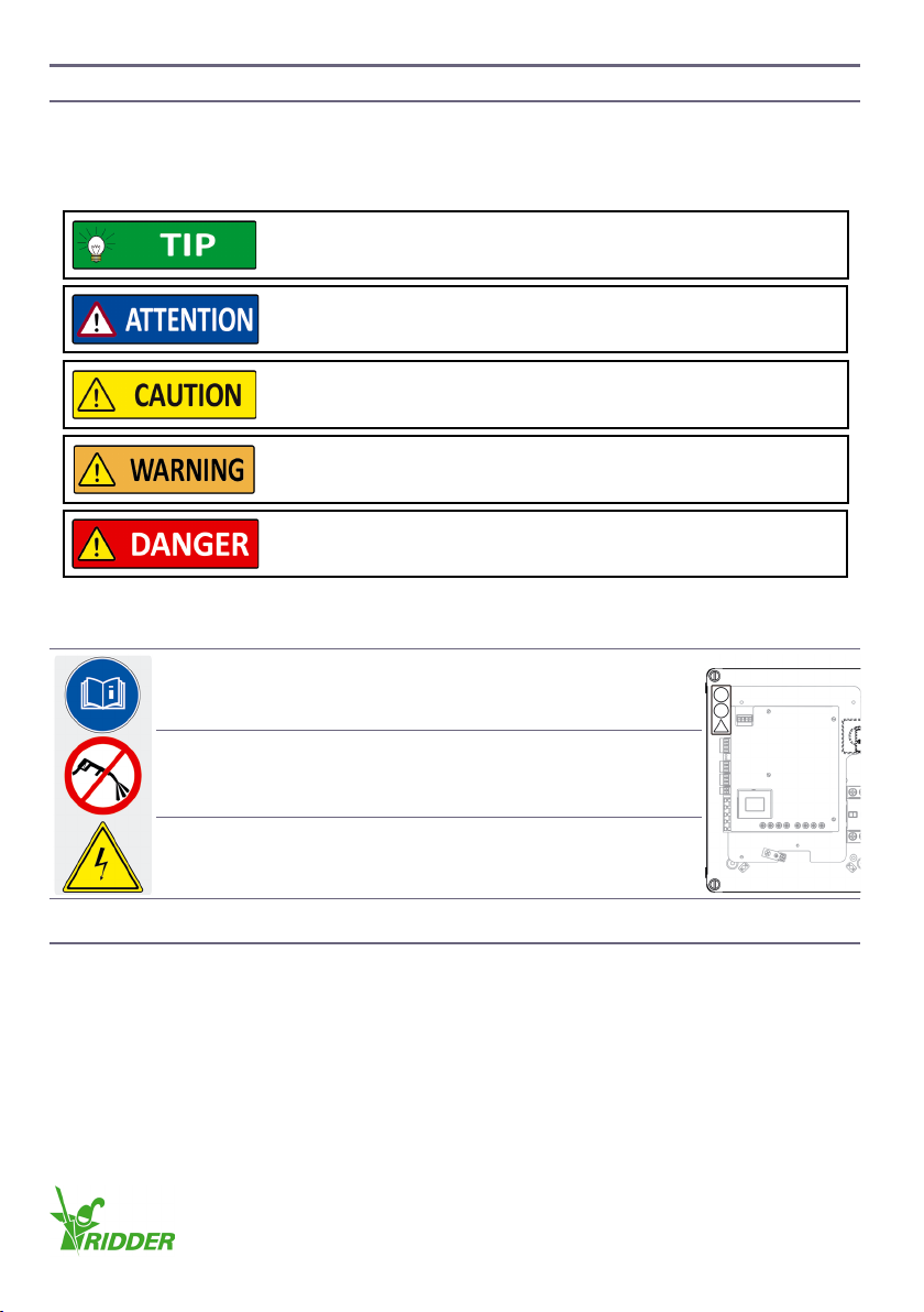
If you do not obey the safety instrucons that follow it can be
dangerous and cause injury.
Ridder Drive Systems B.V.
T+31 (0)341 416 854 - F+31 (0)341 416 611 - Iridder.com
4
Ridder Drive Systems B.V.
T+31 (0)341 416 854 - F+31 (0)341 416 611 - Iridder.com
5

2.3 Residual risks
Automac Controls
The Ridder control-units are usually used in automac controlled systems. Persons who do work
or stay near the system must know about that. If persons or their clothes touch the system during
operaon, it can be dangerous.
Forces
Because of the forces in the systems (in which the control unit is installed), Ridder cannot be sure
that there will be no injury to persons or damage to the system.
2.4 Symbols and abbreviaons
This secon tells about used symbols and abbreviaons in this manual. The table that follows gives
the descripons.
Symbol Description Symbol Description
1L1 Power IN (A2) PE Protecve earth
3L2 Power IN (A2) PTC PTC thermistor
5L3 Power IN (A2) RCB Ridder control-board
2T1 Power OUT (EM) RLS Limit-switch system
4T2 Power OUT (EM) RMC Ridder MotorControl
6T3 Power OUT (EM) RPD Ridder PolyDrive
ACS Automac control-system RPR Ridder PowerRoller
AL Alarm (circuit) RPU Digital posioning-meter
A1 RMC400 housing RSU Limit-switch system
A2 Control board RW Motor gearbox
D1 Status LED - Green SW Width-across-ats
D2 Status LED - Red T1, T2, T3 Load connecon
D3 Status LED - Red U1,V1,W1
U2, W2 Motor connecon
D4 Status LED - Red
EM, M Electric motor, Motor X1 Power input (RCB)
ES11,ES12 Duty switch RSU/RLS X2 Power output (EM)
ES21,ES22 Safety switch RSU/RLS X3 Transformer
GND Return wire of control signal (ACS) X4 PTC input
ICurrent in Amperes (A) X5 Fault-contact output
L1, L2, L3 Voltage source X6 Automac-control input
MC Manual Control X7 RPU reference-input
MPCB Motor-Protecon Circuit-Breaker X8 Manual-control input
N Neutral wire X9 Limit-switch input
Persons can be in danger of life if they touch a system that is in
operaon.
Ridder Drive Systems B.V.
T+31 (0)341 416 854 - F+31 (0)341 416 611 - Iridder.com
6
Ridder Drive Systems B.V.
T+31 (0)341 416 854 - F+31 (0)341 416 611 - Iridder.com
7

3. PRODUCT DETAILS
3.1 Idencaon
EXAMPLE
Ê
This product manual is only applicable to:
• Ridder MotorControl RMC400 control-unit
• Serial numbers from 200.900.000
• Item numbers from 500000.
Idencaon is possible from the scker on the locaon shown.
Refer to the explanaon that follows on how to read the informaon.
For more informaon on item numbers and models refer to the
Ridder catalogue or website at ridder.com.
0.4-0.6: Current (I) in Ampère (A).
3: 3~ mains voltage.
Alternatives
1-3: 1~ -3~ mains voltage.
Alternatives
115-400: Mains voltage 115 V/230 V (1~) or 208 V/400 V (3~).
RMC400: General designaon Ridder RMC400 control units.
1~ - 3~ = 1-phase and 3-phase
0.6-1.0 A, 1.0-1.6 A, 1.6-2.5 A, 2.5-4.0 A, 4.0-6.3 A or 6.3-10 A.
3~ = 3-phase
400: Mains voltage 400 V (3~).
440-600: Mains voltage 440 V, 480 V or 600 V (3~).
Alternatives
Ridder Drive Systems B.V.
T+31 (0)341 416 854 - F+31 (0)341 416 611 - Iridder.com
6
Ridder Drive Systems B.V.
T+31 (0)341 416 854 - F+31 (0)341 416 611 - Iridder.com
7

3.2 Descripon
The RMC400 is a control unit to control Ridder motor-gearboxes. All
the electrical components of the RMC400 control-unit are built-in to
a plasc housing. Supply is with or without a motor-protecon circuit-
breaker (MPCB) and manual control (MC).
The control unit is applicable to:
• Dierent supply voltages
• Dierent mains frequencies
• 3-phase and 1-phase voltages.
The control unit has a control board with a microprocessor and a
semiconductor relay.
The control board has connecons for:
• The supply voltage
• The power supply for the electric motor (EM)
• An automac control signal (24 V AC/DC) from an automac control-system (ACS)
• A manual control (MC) (units without a built-in MC)
• A fault contact (NC) that can be part of an alarm circuit
• A PTC thermistor in the electric motor (EM) for thermal protecon
• A digital posioning-meter (RPU).
The limit-switch system is also connected to the control board of the control unit.
The RMC400 control-unit transmits control signals from the automac control-system (ACS) or
manual control (MC) and monitors if these are processed without malfuncons. The control unit has
rotaonal-eld detecon and phase detecon of the supply voltage.
The 24 V AC/DC control input is protected from:
• Control in two direcons at the same me
• Sudden changes of direcon.
The control unit has status LEDs to show error messages of the system.
The RMC400 control-unit has plug connectors and terminal strips to connect the cables. To pull the
cables through, out of the housing, the control unit also has cable glands. The protecon rang of
the RMC400 housing is IP54.
Ridder Drive Systems B.V.
T+31 (0)341 416 854 - F+31 (0)341 416 611 - Iridder.com
8
Ridder Drive Systems B.V.
T+31 (0)341 416 854 - F+31 (0)341 416 611 - Iridder.com
9

3.3 Applicaon
The control unit is used to control Ridder motor gearboxes in two direcons-of-rotaon.
The RMC400 control-unit is applicable to:
• RW motor gearboxes
• RPR PowerRollers
• RPD PolyDrives.
For other (dierent) applicaons, approval from Ridder Drive Systems is necessary.
3.4 Dimensions
Note: The dimensions and illustraons are approximate. In this product manual shown illustraons
can be dierent than the components and/or systems.
3.5 Technical specicaons
Mechanical
Dimensions (WxHxD) 254 mm x 313 mm x 147 mm (with MC)
254 mm x 313 mm x 117 mm (without MC)
Weight 2.4 - 3.2 kg
Ambient
Protecon rang IP54
Ambient temperature 0 to +60 °C (+32 to +140 °F)
Maximum relave humidity 95%
254
6.5
313
147 231
291
117
3
Ridder Drive Systems B.V.
T+31 (0)341 416 854 - F+31 (0)341 416 611 - Iridder.com
8
Ridder Drive Systems B.V.
T+31 (0)341 416 854 - F+31 (0)341 416 611 - Iridder.com
9

The three types of control boards (RCB) that follow
are available for the RMC400 control-unit.
RCB-A (Type A):
50/60 Hz AC
1~ 115V-230 V, 12FLA, 72 LRA
3~ 208-400 V, 12 FLA, 72 LRA
RCB-B (Type B):
50/60 Hz AC
3~ 400 V, 10 FLA, 60 LRA
RCB-C (Type C):
50/60 Hz AC
3~ 440-600 V, 10 FLA, 60 LRA
Refer to the table that follows for abbreviaons,
technical specicaons and descripons of all
connecons.
Ridder Drive Systems B.V.
T+31 (0)341 416 854 - F+31 (0)341 416 611 - Iridder.com
10
Ridder Drive Systems B.V.
T+31 (0)341 416 854 - F+31 (0)341 416 611 - Iridder.com
11

Electrical
Supply voltage
X1 Power supply Type 1-phase (1~) 3-phase (3~) Current
1L1
3L2
5L3
N*
RCB (A2)
RCB (A2)
RCB (A2)
RCB (A2)
Input
Input
Input
Input
RCB-A
1x 115 VAC
1x 230 VAC
RCB-A
-
-
3x 208 VAC
3x 400 VAC
RCB-B
3x 400 VAC
RCB-C
3x 440-480 VAC
3x 600 VAC
Max 12 A
X2 Power supply Type
2T1
4T2
6T3
N*
Electric motor (EM)
Electric motor (EM)
Electric motor (EM)
Electric motor (EM)
Output
Output
Output
Output
*N is only there on RCB-A.
X3
RCB-A
Transformer Supply voltage
1 2 3 4 5 Type 1-phase (1~) 3-phase (3~) Current
1~ Loop connecon 1x 115 VAC N.A. ~16 mA
1~ Loop connecon 1x 230 VAC N.A. ~10 mA
3~ Loop connecon N.A. 3x 208 VAC ~10 mA
3~ Loop connecon N.A. 3x 400 VAC ~ 4 mA
(X3)
RCB-B
Transformer Supply voltage
1 2 3 4 5 Type 3-phase (3~) Current
3~ N.A. N.A. N.A. 3x 400 VAC
X3
RCB-C
Transformer Supply voltage
1 2 3 Type 3-phase (3~) Current
3~ Loop connecon N.A. 3x 440-480 VAC
3~ Loop connecon N.A. 3x 600 VAC
X4 PTC IN Type Supply voltage Current
1PTC Input 0.25 V DC 1 mA
2PTC’ Power supply 0.25 V DC 1 mA
X5 Fault-contact OUT Type Supply voltage Current
1Not connected Loop-connecon pin Max 350 V Max 50 mA
2Fault OUT Switching contact Max 350 V Max 50 mA
3Fault OUT’ Switching contact Max 350 V Max 50 mA
X6 ACS Type Supply voltage Current
1Direcon B Input 24 V AC/DC 10.5/10 mA
2Common Ground Ground 10.5/10 mA
3Direcon A Input 24 V AC/DC 10.5/10 mA
X7 RPU Type Supply voltage Current
1+24V Power supply 24 V DC 50 mA
2RPU CALIBRATION A Output 24 V DC 0.5/1 mA
3RPU CALIBRATION B Output 24 V DC 0.5/1 mA
4Neutral wire Power supply
Ridder Drive Systems B.V.
T+31 (0)341 416 854 - F+31 (0)341 416 611 - Iridder.com
10
Ridder Drive Systems B.V.
T+31 (0)341 416 854 - F+31 (0)341 416 611 - Iridder.com
11

Electrical
X8 MC Type Supply voltage Current
1+24V Power supply 24 V DC Max 15.7 mA
2Direcon A Input 24 V DC 2.1 mA
3 Auto Input 24 V DC 2.1 mA
4Direcon B Input 24 V DC 2.1 mA
5LED Output 24 V DC 4.7 mA
6LED Output 24 V DC 4.7 mA
X9 Limit-switch IN Type Supply voltage Current
1Common Power supply 7 V DC 3.3 mA
2Direcon B Input 7 V DC 1.1 mA
3Direcon A Input 7 V DC 1.1 mA
4Safety Input 7 V DC 1.1 mA
D1-D4 LED
D1 Green
D2 Red
D3 Red (RPU)
D4 Red (RPU)
4. INSTALL INSTRUCTIONS
Installaon is only permied to approved personnel.
The RMC400 control-unit is available:
• With a built-in motor-protecon circuit-breaker (MPCB) and manual control (MC)
• Without a built-in motor-protecon circuit-breaker (MPCB) and manual control (MC).
Do a check of the supplied parts in the table that follows.
Parts list
580000 RMC400 control-unit 1x 272031 Cable gland M20\IP68\PA\LC 5x
272033 Nut M20 PA 5x
NOTE: The installer must install the supplied cable glands and nuts as necessary.
Ridder Drive Systems B.V.
T+31 (0)341 416 854 - F+31 (0)341 416 611 - Iridder.com
12
Ridder Drive Systems B.V.
T+31 (0)341 416 854 - F+31 (0)341 416 611 - Iridder.com
13

4.1 Special tools and equipment
No special tools or equipment are necessary to install, to connect or for commissioning.
4.2 Installaon
The condions and starng points that follow are applicable for installaon. Make sure that the
working condions comply with the, local or naonal, laws and regulaons.
• Do not remove the product from the packaging unl a short me before the installaon.
• Use the correct work equipment and accessories (belts, chains, pallets or such) if it is not
permied or possible to put the product manually in posion.
• The RMC400 is applicable for wall mounng.
• Make sure that you can see the operated system from all control units and control systems. Put
control units and control systems at a height of more than 1.5 m.
• The RMC400 gives informaon about the system with LEDs on the control board. Thus, easy
access and a sasfactory view is recommended for the locaon of the RMC400.
Removal cover
• Loosen the cover screws (4x, slot ± 9x2 mm) and the cover temporarily to do all necessary work.
The gasket usually stays in its posion.
• Make sure that no damage is caused to the gasket and that it does not become dirty.
• Install the cover again aer the work! Refer to the end of chapter 7.
Make sure that the correct equipment and tools are used.
Make sure that easy access to the cover of the RMC400 control-unit
is possible for all work.
(4x)
Slot
± 9x2 mm
Ridder Drive Systems B.V.
T+31 (0)341 416 854 - F+31 (0)341 416 611 - Iridder.com
12
Ridder Drive Systems B.V.
T+31 (0)341 416 854 - F+31 (0)341 416 611 - Iridder.com
13

Cable glands
• Select the necessary number, and locaon in the boom of the housing, for the cable glands
M20. Refer to the applicable connecons in chapter 5.
• Drill the holes of ø20 mm and install the cable glands (SW24) with the nuts (SW26).
Note: Make sure that no damage is caused to the cables and the control board!
Installaon
• Install the RMC400 unit with four screws or such (maximum ø6 mm/ø11.5 mm) in the mounng
holes. The locaons of the mounng holes (recommended for the IP protecon-rang) are in the
corners of the housing!
5. CONNECT INSTRUCTIONS
Only to approved personnel it is permied to do the connect instrucons.
5.1 Electrical material
A minimum conductor diameter of 1.5 mm² is applicable to the cables in the wiring diagrams. For
the used components, electrical material and cable lengths the necessary conductor diameter can
be dierent.
272033 (5x)
ø20 mm (5x)
28 mm < Y < 40.5 mm SW=24 mm (5x)272031 (5x)
SW=26 mm (5x)
Cables!
Control Board !
Y
Y
< ø11.5 mm (4x)
< ø6 mm (4x)
Use only applicable components and electrical material. Always refer
to the related informaon and manuals.
Ridder Drive Systems B.V.
T+31 (0)341 416 854 - F+31 (0)341 416 611 - Iridder.com
14
Ridder Drive Systems B.V.
T+31 (0)341 416 854 - F+31 (0)341 416 611 - Iridder.com
15

5.2 Protecon - Condions and starng points
The condions that follow are applicable to the wiring diagrams.
• The installer makes sure that necessary and not shown protecons are used and included in the
wiring diagrams.
• If applicable, it is possible to connect a PTC thermistor. Refer to diagrams §5.5, §5.6 and §5.7.
• Protect the electric connecons from moist condions.
Inducon
Problems with inducon must be prevented. Inducon can cause an interference with the
electronics.
Inducon can have many causes such as:
• Cable lengths
• External sources
• Too many cables together.
Electrical connecons are only permied to an electrotechnical
installer or an electrician.
For installaon and maintenance work the system must be de-
energized.
Always make sure that the protecons comply with the, local or
naonal, laws and regulaons of the country.
The installer sets the Motor-Protecon Circuit-Breaker (MPCB) to the
value of the nominal current of the electric motor.
The RMC400 does not have a short-circuit protecon and overload
protecon. To get the necessary safety, refer to the local or naonal
laws and regulaons of the country.
Separaon of cables is necessary. This prevents problems with
inducon.
Ridder Drive Systems B.V.
T+31 (0)341 416 854 - F+31 (0)341 416 611 - Iridder.com
14
Ridder Drive Systems B.V.
T+31 (0)341 416 854 - F+31 (0)341 416 611 - Iridder.com
15

5.3 Overview and funcon diagram
The diagram that follows shows the RMC400 control-unit in a system. Ridder Drive Systems
connects the components (if applicable) in the framework A1.
5.4 Wiring diagram: Control board (RCB)
The diagrams that follow show:
• The RMC400 housing (A1) and the RCB control-board (A2)
• The standard connecons and oponal connecons with related connectors
• The related secons with the wiring diagrams and informaon.
If units have a built-in MPCB and MC, then Ridder connected:
• X1 to the motor-protecon circuit-breaker (MPCB) with standard 3-phase connecons. If
applicable, refer to the related secons (§5.6/§5.7) to change to 1-phase connecons!
• X8 to the manual control (MC).
Alarm
Automac Control Manual Control
Control Board
Supply Voltage
Temperature
Limit Switch
Power Supply 24 V DC
Supply Voltage
24 V AC/DC Control
Fault Contact
OPTIONAL
OPTIONAL
Reference Monitoring
Posion Feedback
OPTIONAL
Ridder Drive Systems B.V.
T+31 (0)341 416 854 - F+31 (0)341 416 611 - Iridder.com
16
Ridder Drive Systems B.V.
T+31 (0)341 416 854 - F+31 (0)341 416 611 - Iridder.com
17

RMC400 housing:
RMC400 control-board (RCB):
OPTIONAL
Alarm
§5.12 OPTIONAL
§5.10 OPTIONAL
§5.11 OPTIONAL §5.5/ §5.6/ §5.7
CONTROL BOARD A2 (RCB)
Manual Control
Posion Feedback
Power In
* X3 is not there on RCB-B
Automac Control Transformer Conguraon Power Out
§5.9
Limit Switch Thermal Protecon
§5.5/ §5.6/ §5.7
§5.8
Ridder Drive Systems B.V.
T+31 (0)341 416 854 - F+31 (0)341 416 611 - Iridder.com
16
Ridder Drive Systems B.V.
T+31 (0)341 416 854 - F+31 (0)341 416 611 - Iridder.com
17

5.5 3-phase electric motor (208-600 VAC)
• Make sure that the conguraon (RCB-A or C) on X3 (TRANSFORMER) agrees with the supply
voltage!
• Connect the electric motor (EM) to X2 (MOTOR).
• If applicable, remove the jumper from X4 and connect EM to X4 (PTC)
• Connect the supply voltage to the MPCB (if applicable) or X1 (MAINS), and PE (protecve earth).
Control board A2
(Out) (In)(In)
6 x 1,5 mm²
4 x 1,5 mm²
YES NO
Ridder Drive Systems B.V.
T+31 (0)341 416 854 - F+31 (0)341 416 611 - Iridder.com
18
Ridder Drive Systems B.V.
T+31 (0)341 416 854 - F+31 (0)341 416 611 - Iridder.com
19

5.6 1-phase 3-wire electric motor (115-230 VAC)
• Make sure that the conguraon (RCB-A) on X3 (TRANSFORMER) agrees with the supply voltage!
• Connect the electric motor (EM) to X2 (MOTOR).
• If applicable, remove the jumper from X4 and connect EM to X4 (PTC)
• If the unit has a built-in MPCB, make sure to change the standard 3-phase connecons to 1-phase
connecons! The diagram of §5.5 (X1) must change to the diagram of §5.6 (X1, X2, MPCB).
• Connect the supply voltage to the MPCB (if applicable) or X1 (MAINS), and PE (protecve earth).
Control board A2
(Out) (In)(In)
6 x 1,5 mm²
3 x 1,5 mm²
YES NO
Ridder Drive Systems B.V.
T+31 (0)341 416 854 - F+31 (0)341 416 611 - Iridder.com
18
Ridder Drive Systems B.V.
T+31 (0)341 416 854 - F+31 (0)341 416 611 - Iridder.com
19

5.7 1-phase 5-wire electric motor (115-230 VAC)
• Make sure that the conguraon (RCB-A) on X3 (TRANSFORMER) agrees with the supply voltage!
• Connect the electric motor (EM) to X2 (MOTOR).
• If applicable, remove the jumper from X4 and connect EM to X4 (PTC)
• If the unit has a built-in MPCB, make sure to change the standard 3-phase connecons to 1-phase
connecons! The diagram of §5.5 (X1) must change to the diagram of §5.7 (X1, X2, MPCB).
• Connect the supply voltage to the MPCB (if applicable) or X1 (MAINS), and PE (protecve earth).
5.8 Limit switch (RSU/RLS)
Connect a limit switch (RSU/RLS) to X9 of the control board (A2). Refer to the diagram that follows.
Also refer to the product manual of the used Ridder motor-gearbox at ridder.com.
Control board A2
(Out) (In)(In)
8 x 1,5 mm²
3 x 1,5 mm²
YES NO
Control board A2
Common
Safety
Safety switches
Duty switch
Duty switch
Ridder Drive Systems B.V.
T+31 (0)341 416 854 - F+31 (0)341 416 611 - Iridder.com
20
Ridder Drive Systems B.V.
T+31 (0)341 416 854 - F+31 (0)341 416 611 - Iridder.com
21
Table of contents
Other Ridder Control Unit manuals
Popular Control Unit manuals by other brands

WEISS ROBOTICS
WEISS ROBOTICS CLG Series Mounting and operating instructions

Quectel
Quectel RM502Q-GL Hardware design

Festo
Festo VZWD-L-M22C-M Series operating instructions

Conductix-Wampfler
Conductix-Wampfler iDM-MCU operating manual

MicroNova
MicroNova Mercury 2 Reference manual

Exodraft
Exodraft EFC21 user guide