RIDLEY ACOUSTICS KVW625 User manual

Ridley Acoustics KVW625
6.5 inch Long Throw In-Wall Speakers
6 1/2" TWO-WAY
Congratulations! You have pur-
chased a high quality stereo loud-
speaker. When matched to compa-
rable electronic equipment, expect
years of quality high fidelity sound.
We are constantly striving to pro-
vide the very best technology has to
offer.
The following manual is designed
to give you, the installer or owner,
basic information as to the
speaker’s installation and operation.
It is beyond the scope of this man-
ual to go into all the details that
must be taken into consideration in
a sophisticated high fidelity system.
If you have any questions regard-
ing this speaker which are not an-
swered by this manual, please feel
free to contact your local dealer.
GENERAL DESCRIPTION
These two-way speakers have
specially designed 5 1/4" and 6 1/2"
woven Kevlar cone woofers with
linear long throw butyl rubber edge
surrounds. A pivoting 1" soft dome
tweeter is utilized for excellent high
frequency dispersion throughout
your entire listening environment.
Sophisticated crossover networks
separate the audio signal and direct
the proper frequencies to the driver
that will reproduce them best.
These crossovers are specifically
designed for these speakers to en-
sure maximum high fidelity.
SHIPPING DAMAGE
Each speaker is thoroughly tested
before it leaves the factory. How-
ever, in shipment, accidents may
occur. Please inspect your speak-
ers carefully when you receive them
to make sure there is no damage.
If there is, please notify your dealer,
or supplier immediately for assis-
tance. If you received your speak-
ers by public transportation, report
the damage at once to the shipping
company.
AMPLIFIER OPERATION
These speakers are equipped
with a special automatic polyswitch
circuit which, when overdriven, will
automatically restrict electrical cur-
rent to the tweeter to prevent dam-
age. The circuit will automatically
re-engage once the volume is
turned down or the problem is re-
moved. This normally takes about
thirty (30) seconds to occur.
The speaker will perform well with
amplifiers from 15 to 100 Watts
RMS. However, any speaker can
be damaged or its protective cir-
cuitry engaged by any size amplifier
that is being overdriven into clip-
ping. “Amplifier clipping” is a
phrase used to describe a condition
when, because of the volume de-
mand, an amplifier is being asked
for more power than it can give. If
you should find that your protective
circuits on the tweeter are activated
often, please consider reducing the
volume at which you normally play
the speaker or purchasing a larger
amplifier with more reserve power.
DAMAGE DONE TO A SPEAKER
BY CLIPPING IS NOT COVERED
UNDER THE WARRANTY.
SPEAKER PLACEMENT
Placement of the Wall Mounted
Speakers in your room should be
carefully considered. They should
be located where they will provide
you with the best possible sound
and the greatest ease of installa-
tion.
It is beyond the scope of this pub-
lication to discuss all of the various
aspects of speaker placement.
Please feel free to contact your
dealer.
WIRING
To achieve maximum perform-
ance from your new speakers, we
strongly suggest the use of special
low inductance stereo cable. There
are many good brands presently on
the market. The cable should be at
least 16 gauge or larger. Speaker
wire smaller than 16 gauge, which
is sometimes clear coated, will sig-
nificantly decrease your speaker’s
performance. The larger the wire
is, the better. It is important when
installing your speakers and/or run-
12 1/8"
3 1/4" 8 5/8"

ning wire through your house that
you consult any local codes and
requirements to make sure that
safety is being adhered to. We
suggest that a professional be con-
sulted in order to maximize your
system’s performance. The follow-
ing, however, are just a few of the
do’s and don'ts:
1. Try to keep the wire length to a
minimum. Runs of over 50 feet
should have 16 gauge or heavier
wire.
2. Avoid routing speaker cables
near electrical cables. This will
help reduce hum and RF inter-
ference.
3. In securing your wire, do not sta-
ple or nail it. By doing so, a
short could occur in your wire
and not only significantly reduce
your system’s performance, but
damage your electronics, i.e.
amplifier, as well.
4. Allow about 2 ½ feet of free wire
at the cut-out to aid in the ease
of installation of your speakers.
More than two pair of these
speakers can be installed to one
amplifier. However, we suggest
that if you are installing more
than two pair, please consult a
professional.
5. In checking your speakers, make
sure proper phasing is main-
tained. Simply put, this means
being sure the same wire which
is hooked to the positive terminal
of the amplifier is hooked to the
positive terminal of the speaker.
It is important to check this on all
speakers. If one speaker is
hooked up incorrectly, or out of
phase, the quality of your bass
will be seriously impaired.
INSTALLATION
As the diagrams show, the
speaker utilizes a metal mounting
ring which, after tightening with the
screws provided, acts as a clamp to
hold the speaker in place.
To aid in speaker performance, a
fibrous material, such as fiberglass
or polyester fiber, may be placed
behind the speaker to help elimi-
nate unwanted sound from being
transmitted into adjoining rooms.
Professional installers use quality
equipment. The better the equip-
ment, the better the installation.
Once you determine where you
wish the speakers to be placed, do
the following:
Using the paper template pro-
vided and the proper equipment,
cut the appropriate sized hole in the
wall making sure that where you
wish the speakers to be placed will
not be obstructed by a stud or other
material hidden in the wall. On dry-
wall, the cleanest cuts will be made
with a utility knife. Otherwise, you
may need to use a keyhole saw or
other suitable equipment.
If it was done correctly, you
should be able to reach the speaker
wire through the hole. Pull the wire
out of the wall and hook it up to the
terminals on the back of the
speaker assembly, observing polar-
ity (+ & -).
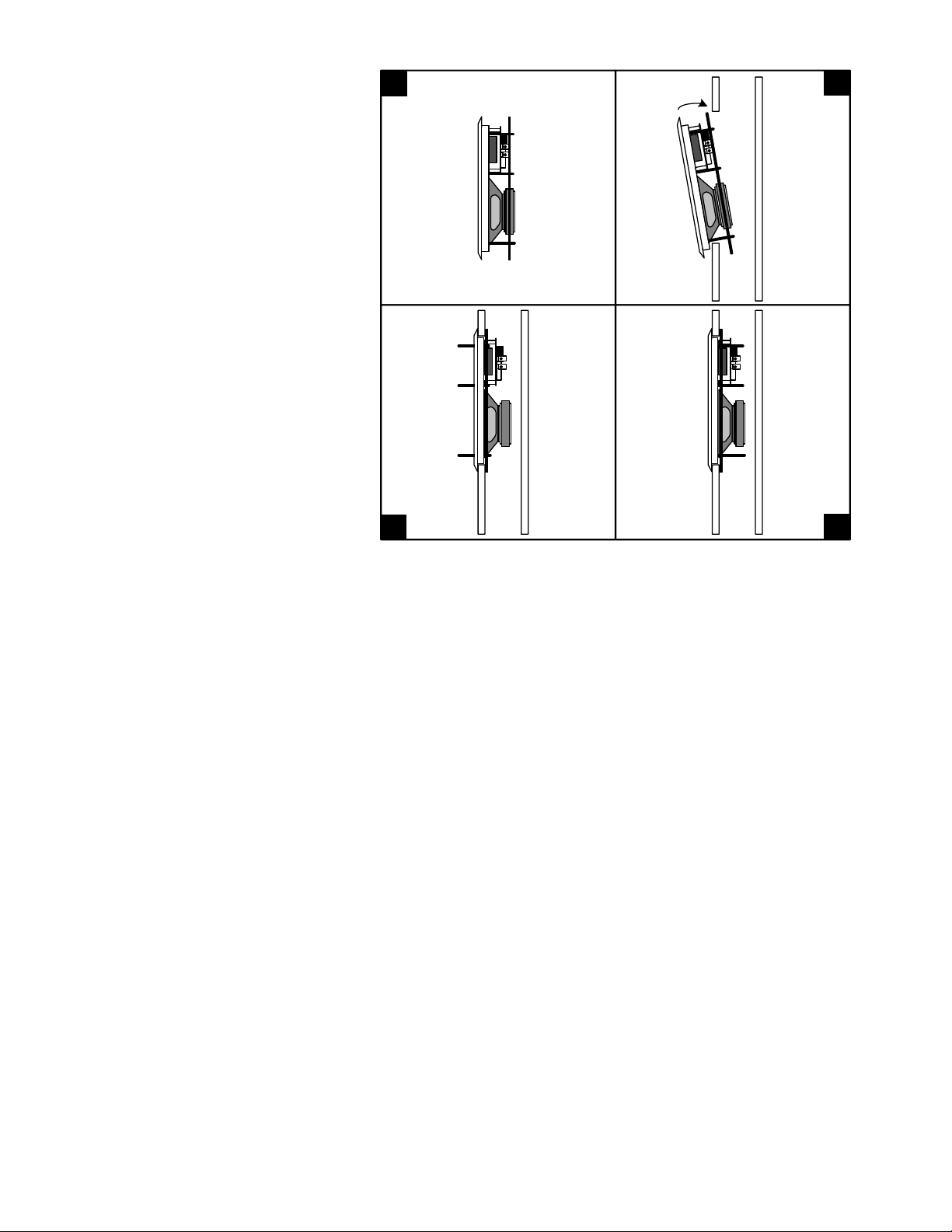
Install the frame and mounting
ring assembly by passing the black
mounting ring through the cut-out
as illustrated above in figures 1 and
2. Next, verify that the speaker
frame fits into the cut-out. The
white frame should fit snugly and
smoothly in the cut-out hole. How-
ever, if the hole should have been
cut a little too large, there is an
overlapping frame on the speaker
that will cover this.
Once the frame is in place, pull
on two of the screws so that the
mounting ring is up against the
back side of the wall board and all
of the screws protrude out toward
you (see fig. 3). While holding one
of the screws so that the clamp ring
stays against the wall, screw all of
the screws in until the clamp is
snug (see fig. 4). Start with the
middle pair of screws followed by
the top pair and then the bottom
pair. Be careful not to over tighten.
12
4
3

SPECIFICATIONS
This speaker is a 6 1/2" electrodynamic
loudspeaker system designed to be flush
mounted in a wall or panel. A retro-fit clamp-
ing ring for mounting into an existing wall is
included. A new construction rough-in kit is
available as an optional accessory.
The loudspeaker mounts in an opening
accessible from the front without access to
the rear. The speaker has an overlapping
edge capable of covering discrepancies in
the mounting opening.
The loudspeaker has a perforated metal
grille to protect the driver and is removable
for servicing. All surfaces of the speaker in
the room are paintable.
The frame is of ABS material that is heat
resistant up to 120 degrees. The loud-
speaker is designed so as to perform cor-
rectly in an infinite baffle design requiring no
rear chamber.
The loudspeaker is comprised of a low
frequency driver and a separate high fre-
quency driver. The low frequency driver is
manufactured with a woven Kevlar cone,
phase plug pole piece extension, and butyl
surround. The high frequency driver is an
"eyeball" soft textile dome with a 1" diameter
voice coil for safe power handling capacity.
It also has a polyswitch protection circuit
which is non-mechanical and self-resetting.
The crossover is a 2nd order network (12 dB/
oct) and delivers two specific ranges of fre-
quencies to each the woofer and the tweeter.
(Cut-out Dimensions: 7 3/8" W x 10 7/8" H)
12 1/8"
3 1/4" 8 5/8"
- 6 1/2" long throw black Kevlar woofer
with butyl surround and Phase Plug
pole piece
- 1" pivoting textile soft dome tweeter
- 91 dB sensitivity
- 12 dB/Octave crossover
- Poly-switch overdrive protection
- IR receiver knock-out
- Steel clamp ring mounting system.
- Frequency Response: 45 Hz - 20,000Hz
- Power Handling: 80 watts
- 8 Ohms
- 25 Year Transferable Warranty
Cut-out Dimensions:
Inches: 7 3/8 "W x 10 7/8" H x 3 1/8" D
Centimeters: 19cm W x 28cm H x 8cm D
Overall Dimensions:
Inches: 8 5/8" W x 12 1/8" H
Millimeters: 22cm W x 31cm H
Website: www.ridleyacoustics.co.uk
Other RIDLEY ACOUSTICS Speakers manuals