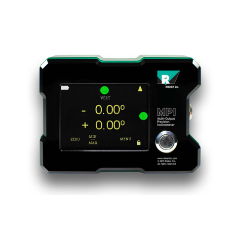
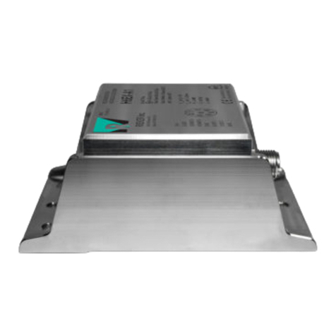
RIEKER Flex H6EX-A1 User manual

Current 0..24mA
Voltage 0..10V
Digital RS485
Dual Axis
Up to 360º
Inclinometers
For
Hazardous Locations
2019 Flex™ H6EX-A1 Installation Manual

H6EX-A1 Installation Manual
Rev B
Page 1 of 8
RIEKER INC • 34 MOUNT PLEASANT ROAD • ASTON • PA • 19014 • USA
610-500-2000 fax: 610-500-2002 [email protected] www.riekerinc.com
The information and material presented may not be published, broadcast, rewritten, or redistribute
d without the expressed written consent of Rieker
®
Inc.
This document is a Specification Control Document and may not be modified without prior agency approval
.
©201
8 Rieker®All Rights Reserved.
FORM NUMBER:
H6EX0009_05/18 UPDATED: 10/24/19
Table of Contents
Sensor Description ......................................................................................................2
Hazardous Location Information..................................................................................2
Applicable Standards...................................................................................................3
H6EX-A1 Instructions for Safety..................................................................................4
Putting into Service ..............................................................................................4
Use.......................................................................................................................4
Assembling and Dismantling ................................................................................4
Maintenance.........................................................................................................5
Installation and Mounting:.....................................................................................5
Adjustment ...........................................................................................................6
Markings......................................................................................................................7
H6EX-A1 Connector Wiring Tables .............................................................................8
List of Figures
FIGURE 1: H6EX-A1 CONTROL DRAWING ........................................................................................................................ 4
FIGURE 2: H6EX-A1 DIMENSIONS AND MOUNTING (INCHES [MM]) .................................................................................... 5
FIGURE 3: H6EX-A1 AXIS ORIENTATIONS ........................................................................................................................ 6
FIGURE 4: TOP SURFACE MARKINGS FOR MODEL AND HA ARDOUS LOCATION INFORMATION ................................................... 7
FIGURE 5: FRONT SURFACE MARKINGS FOR SERIAL NUMBER ............................................................................................... 7
FIGURE 6: FACTORY CONFIGURED DEFAULTS LABEL ........................................................................................................... 7

H6EX-A1 Installation Manual
Rev B
Page 2 of 8
RIEKER INC • 34 MOUNT PLEASANT ROAD • ASTON • PA • 19014 • USA
610-500-2000 fax: 610-500-2002 [email protected] www.riekerinc.com
The information and material presented may not be published, broadcast, rewritten, or redistribute
d without the expressed written consent of Rieker
®
Inc.
This document is a Specification Control Document and may not be modified without prior agency approval
.
©201
8 Rieker®All Rights Reserved.
FORM NUMBER:
H6EX0009_05/18 UPDATED: 10/24/19
Sensor Des ription
The H6EX-A1 sensor is an Intrinsically Safe inclinometer that provides high accuracy, dual a is inclination over a
range of ±180° for Hazardous Locations. It is ATEX/IECE /MET (US)/CSA approved for use in Class 1, Division 1
and Zone 0 hazardous locations. The H6EX-A1 must be used with a certified isolation barrier.
This sensor incorporates MEMS accelerometers referenced to gravity with integrated temperature
compensation over the full operating range of -40° to +65°C for absolute accuracy. It has both digital (RS485)
and analog (current or voltage) output options available. Each output is linear with respect to the input angle
directly.
The digital RS485 output uses two-wire, half duple communication, along with a Rieker specific protocol. This
protocol can be used to measure the angle of both a es, as well as configure many of the parameters of the
sensor.
The H6EX-A1 provides two continuous, fully configurable, analog outputs. These outputs are individually
settable to current from 0mA to 24mA or voltage from 0V to 10V, are settable to either a is, and are factory or
user configurable to match any angle range and min/ma analog values.
Hazardous Lo ation Information
Intrinsically safe equipment is defined as “equipment which is incapable of releasing sufficient electrical or
thermal energy under normal or abnormal conditions to cause ignition of a specific hazardous atmosphere
mixture in its most easily ignited concentration.”
The H6EX-A1 is ATEX / IECEx approved to:
E II 1G E ia IIC T4 Ga (-40°C≤T
amb
≤+65°C)
E ia IIC T4 Ga (-40°C≤T
amb
≤+65°C)
The H6EX-A1 is also US and Canada approved to:
Class I, Division 1, Groups A, B, C, D
Class I, Zone 0, AE ia IIC T4 Ga (-40°C≤T
amb
≤+65°C)
Certifi ate Numbers:
SEV 18 ATEX 0217
IECE SEV 18.0042
MET E114209
The H6EX-A1 sensor is intrinsically safe and suitable for all areas e cept mining (Group II / Class 1), can be
used in areas with continuous, long or frequent periods of e posure to hazardous gas (Zone 0 / Division 1), is
suitable for e plosive gas types Groups IIA to IIC and A to D, and has temperature group T4. It also has an
e tended operating temperature range of -40°C to +65°C.
WARNING: If the equipment is used in a manner not specified by the manufacturer, the protection provided by
the equipment may be impaired.
AVERTISSEMENT: Si l’équipement est utilisé de façon non spécifiée par le fabricant, la protection assurée par
l’équipement peut être altérée.

H6EX-A1 Installation Manual
Rev B
Page 3 of 8
RIEKER INC • 34 MOUNT PLEASANT ROAD • ASTON • PA • 19014 • USA
610-500-2000 fax: 610-500-2002 [email protected] www.riekerinc.com
The information and material presented may not be published, broadcast, rewritten, or redistribute
d without the expressed written consent of Rieker
®
Inc.
This document is a Specification Control Document and may not be modified without prior agency approval
.
©201
8 Rieker®All Rights Reserved.
FORM NUMBER:
H6EX0009_05/18 UPDATED: 10/24/19
Appli able Standards
Normal Lo ations
•UL 61010 -1 3
rd
ed.–Electrical Equipment For Measurement, Control, and Laboratory Use; Part 1
•CSA 61010-1 3
rd
ed. – Electrical Equipment For Measurement, Control, and Laboratory Use; Part 1
•IEC 61010-1:2017 ed. 3.1 - Safety requirements for electrical equipment for Measurement, Control, and
Laboratory Use; Part 1
Hazardous Lo ations
•IEC60079-0:2011 – Electrical Apparatus for E plosive Gas Atmospheres Part 0: General Requirements
•EN60079-0:2012+A11:2013 – Electrical Apparatus for E plosive Gas Atmospheres Part 0: General
Requirements
•CAN/CSA-C22.2 No. 60079-0:15 E plosive Atmospheres–Part 0: Equipment – General Requirements
Intrinsi Safety
•IEC60079-11:2011 – Electrical Apparatus for E plosive Gas Atmospheres Part 11: Intrinsic Safety "i"
•EN60079-11:2012– Electrical Apparatus for E plosive Gas Atmospheres Part 11: Intrinsic Safety "i"
•UL 913, 8
th
ed. – Intrinsically Safe Apparatus and Associated Apparatus for use in Class I, II, and III,
Division 1, Hazardous (Classified) Locations.
•CAN/CSA-C22.2 No. 60079-11:14 E plosive Atmospheres Part 11: Equipment protection by Intrinsic Safety
"i"
EMC
•EN 61326-1:2013 – Electrical equipment for measurement, control and laboratory use — EMC
requirements
•47 CFR Ch. 1 – FCC Part 15 Class A – Radio Frequency Devices – Subpart B – Unintentional Radiators
•ICES-003 – Issue 6 January 2016 Class A –Interference-Causing Equipment Standard – Digital Apparatus

H6EX-A1 Installation Manual
Rev B
Page 4 of 8
RIEKER INC • 34 MOUNT PLEASANT ROAD • ASTON • PA • 19014 • USA
610-500-2000 fax: 610-500-2002 [email protected] www.riekerinc.com
The information and material presented may not be published, broadcast, rewritten, or redistribute
d without the expressed written consent of Rieker
®
Inc.
This document is a Specification Control Document and may not be modified without prior agency approval
.
©201
8 Rieker®All Rights Reserved.
FORM NUMBER:
H6EX0009_05/18 UPDATED: 10/24/19
H6EX-A1 Instru tions for Safety
Putting into Servi e
The H6EX-A1 must be used with a certified Isolation Barrier to supply a nominal +12VDC. The H6EX-A1 has the
following entity parameters:
FIGURE 1: H6EX-A1 Control Drawing
Notes:
A. The H6EX-A1 requires up to three barriers for operation:
1. A barrier to supply a nominal 12VDC to the unit (pins 1 and 2).
2. A barrier to protect the two analog outputs (pins 6 and 7).
3. A barrier to protect the RS485 lines (pins 3 and 4).
(See note C)
C. The H6EX-A1 ground (pin 2) and all attached barrier grounds MUST be connected together so that V
ma
never e ceeds its
allowed voltage.
D. I
ma
(or I
i
) is the sum current of all attached barriers.
E. All grounding path connections should be secure, permanent, visible, and accessible. The grounding path resistance
from the farthest barrier to the grounding electrode should not e ceed 1 ohm.
F. The installation must be in accordance with the National Electrical Code, NFPA 70, Articles 504 and 505, Canadian
Electrical Code C22.1 Section 18, and ANSI/ISA-RP12.06.01.
Use
The sensor is designed to measure dual-a is inclination and output an analog and/or digital signal.
Assembling and Dismantling
The H6EX-A1 shall not be serviced, dismantled, or re-assembled by the user.

H6EX-A1 Installation Manual
Rev B
Page 5 of 8
RIEKER INC • 34 MOUNT PLEASANT ROAD • ASTON • PA • 19014 • USA
610-500-2000 fax: 610-500-2002 [email protected] www.riekerinc.com
The information and material presented may not be published, broadcast, rewritten, or redistribute
d without the expressed written consent of Rieker
®
Inc.
This document is a Specification Control Document and may not be modified without prior agency approval
.
©201
8 Rieker®All Rights Reserved.
FORM NUMBER:
H6EX0009_05/18 UPDATED: 10/24/19
Maintenan e
No maintenance is required.
Installation and Mounting:
1. On the mounting plane, prepare surface with
three tapped holes, H1-H3 for M4/M4.5
mounting screws. H2& H3 are 3.815”
[96.9mm] from H1. See Figure 2. NOTE that
the single hole on the side with the two slots
is not meant to be used for mounting.
2. Mount inclinometer to mounting plane using
M4/M4.5 mounting screws. Use the two slots
for fine adjustments.
Default Horizontal ount Option: Axis
Orientation
The 0° orientation for the horizontal-mount option
H6EX-A1 is a desktop, level position.
•For the X-a is, looking at the unit from
the side with the connector facing to the
right (top right of Figure 3), a clockwise
rotation from the zero position is
considered positive and a counter-
clockwise rotation from the zero position
is considered negative.
•For the Y-a is, looking at the unit from
the front with the connector facing
towards you (top left of Figure 3), a
clockwise rotation from the zero position
is considered positive and a counter-
clockwise rotation from the zero position
is considered negative.
Alternate Vertical ount Option: Axis
Orientation
The 0° orientation for the vertical-mount option of the H6EX-A1 is a vertical position with the connector down.
•For the X-a is, looking at the unit from the top side with the connector facing down (bottom left of
Figure 3), a clockwise rotation from the zero position is considered positive and a counter-clockwise
rotation from the zero position is considered negative.
•For the Y-a is, looking at the unit from the side with the connector facing down and the mounting
surface to the left (bottom right of Figure 3), a clockwise rotation from the zero position is considered
positive and a counter-clockwise rotation from the zero position is considered negative.
FIGURE 2: H6EX-A1 Dimensions and Mounting (In hes [Mm])

H6EX-A1 Installation Manual
Rev B
Page 6 of 8
RIEKER INC • 34 MOUNT PLEASANT ROAD • ASTON • PA • 19014 • USA
610-500-2000 fax: 610-500-2002 [email protected] www.riekerinc.com
The information and material presented may not be published, broadcast, rewritten, or redistribute
d without the expressed written consent of Rieker
®
Inc.
This document is a Specification Control Document and may not be modified without prior agency approval
.
©201
8 Rieker®All Rights Reserved.
FORM NUMBER:
H6EX0009_05/18 UPDATED: 10/24/19
Adjustment
No mechanical adjustment is required.
No software adjustments of H6EX-A1 analog output parameters are permitted. Scaled analog parameters can
only be factory-set and must be selected at time of purchase.
FIGURE 3: H6EX-A1 Axis Orientations

H6EX-A1 Installation Manual
Rev B
Page 7 of 8
RIEKER INC • 34 MOUNT PLEASANT ROAD • ASTON • PA • 19014 • USA
610-500-2000 fax: 610-500-2002 [email protected] www.riekerinc.com
The information and material presented may not be published, broadcast, rewritten, or redistribute
d without the expressed written consent of Rieker
®
Inc.
This document is a Specification Control Document and may not be modified without prior agency approval
.
©201
8 Rieker®All Rights Reserved.
FORM NUMBER:
H6EX0009_05/18 UPDATED: 10/24/19
Markings
The H6EX-A1 shall be marked with the following markings:
FIGURE 4: Top Surfa e Markings for Model and Hazardous Lo ation Information
FIGURE 5: Front Surfa e Markings for Serial Number
In addition, the factory defaults label, located on the bo of the H6EX-A1 sensor, provides the configured
analog output parameters.
FIGURE 6: Fa tory Configured Defaults Label

H6EX-A1 Installation Manual
Rev B
Page 8 of 8
RIEKER INC • 34 MOUNT PLEASANT ROAD • ASTON • PA • 19014 • USA
610-500-2000 fax: 610-500-2002 [email protected] www.riekerinc.com
The information and material presented may not be published, broadcast, rewritten, or redistribute
d without the expressed written consent of Rieker
®
Inc.
This document is a Specification Control Document and may not be modified without prior agency approval
.
©201
8 Rieker®All Rights Reserved.
FORM NUMBER:
H6EX0009_05/18 UPDATED: 10/24/19
H6EX-A1 Conne tor Wiring Tables
TABLE 1: H6EX-A1 MALE 8-PIN INPUT CONNECTOR WIRING
PIN FUNCTION
1 SUPPLY VOLTAGE +12VDC
2 POWER / SIGNAL COMMON
3 RS-485 D+
4 RS-485 D-
5 NO CONNECTION
6 ANALOG OUTPUT 1
7 ANALOG OUTPUT 2
8 NO CONNECTION
TABLE 2: CURRENT SENSE
R
sense
is dependent upon supply voltage and cable/wire resistance.
Ensure the following equation is met:
QUICK REFERENCE
SUPPLY VOLTAGE SENSE RESISTOR
12V 200-350 OHMS
NOTE: The H6EX-A1 Sensor’s Chassis Ground is NOT the same as the signal ground for the current output
return. The analog output return must be connected to the POWER/SIGNAL COMMON (pin 2).
Table of contents
Other RIEKER Measuring Instrument manuals