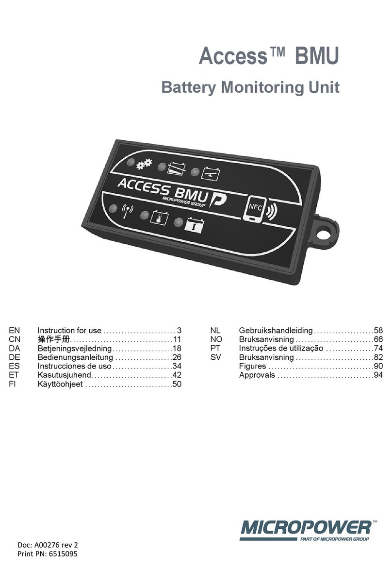
MICRO-POWER Access BMU Series User manual


ENGLISH
Access™ BMU -
Instruction for use
General
Access™ BMU is designed for monitoring vented
lead-acid batteries. The unit is mounted on the
battery and monitors current, voltage, temperature,
electrolyte level and voltage balance.
The functions in Access™ BMU are activated,
deactivated and adapted using the PC software
Access™ Service tool.
Access™ BMU is permanently mounted on the
battery or used as a temporary instrument for
troubleshooting or operating analysis.
When using Access™ BMU together with the
Access™ battery charger, the battery charger is
sent battery specific parameters from the battery
monitoring unit for optimal charging of the battery.
The status of the battery can be read on the
charger’s display.
Information about the charging and discharging
process, the battery status and deviations are
stored internally in the unit. Access™ BMU
communicates wirelessly with other Access™
units.
Information concerning the product’s part number,
serial number and rating can be found on the rear
of the unit.
Safety
Warning information
Hazardous situations and precautionary measures
are presented in the text as set out below.
Warning
Situations that may result in severe personal injury
or death if the instructions are not followed.
Caution
Situations that may result in personal injury or
damage to the product if the instructions are not
followed.
Note:
Information that is important without being related
to safety.
General
Always keep the manual in the vicinity
of the product.
The manual contains important
information about safety and user
instructions.
Read and understand these instructions, the
instructions supplied by the battery manufacturer
with the battery and the employer’s safety
instructions before the product is used, installed or
serviced.
Only qualified personnel may install, use or service
this product.
ELECTRIC SHOCK
The battery may contain voltage on a
level that may cause personal injury.
Warning
Do not touch uninsulated battery terminals,
connections or other live parts.
EXPLOSIVE GASES
Hydrogen gas is produced when
charging lead-acid batteries; this can
cause an explosion.
Do not smoke, cause sparks or use an
open flame in the vicinity of batteries.
3

ENGLISH
Warning
Risk of explosion!
Do not smoke, cause sparks or use a naked flame
in the vicinity of batteries.
Arcing can injure the operator or damage the
battery connector.
Ensure that the charging parameters have been
set correctly according to the battery
manufacturer’s specification.
Do not use the battery if the battery monitoring unit
or its cabling are damaged.
Use insulated tools designed for working on
batteries.
Only perform charging in a well
ventilated environment.
Acceptance
On delivery, visually check the unit for signs of
physical damage.
Check that delivered parts correspond with the
consignment note. Contact your supplier if
anything is missing, see Contact information.
Description
Access™ BMU
See Fig. 2
1. Indication of high battery temperature (red)
2.
3. Indication for the specified time and date
(green)
4. Indication of the network status (green)
5.
6. Magnetic switch network management
Installation
Warning
Electrolyte is corrosive!
If electrolyte comes into contact with the eye,
damage can occur very quickly.
Rinse the eye immediately and thoroughly for at
least 10 minutes, seek medical attention.
Wear protective equipment such as safety glasses
and gloves to avoid contact with the electrolyte.
Note:
Installation may only be performed by qualified
installers.
Follow the battery supplier’s instructions for
handling batteries.
Access™ BMU is solely designed for use with
lead-acid batteries up to 96 V nominal DC voltage.
Consult the manufacturer regarding all other
usage.
Ensure that the Access™ BMU is installed by a
qualified installer in accordance with the
instructions.
Access™ BMU must be well protected against
mechanical damage during daily use, servicing
and maintenance.
Instructions
A threaded insert must be installed to connect
Access™ BMU on the lead terminals of the battery
and cells.
Installation of the threaded inserts
1. Drill a 5.5 mm (0.219 inch) hole in the
appropriate lead terminal. The depth of the hole
must be at least 7.7 mm (0.302 inch).
2. Knock the supplied threaded insert into the
hole.
Now secure the cable lug, use the supplied
washers and screws.
Installation of BMU
1. Locate the battery’s two midmost cells.
The current sensor must be attach between
these cells.
Example: On a 24 V battery it is cells 6 and 7.
4

ENGLISH
2. Install the current sensor (Fig. 1 pos ) between
the midmost cells. See Installation of the
threaded inserts.
The current sensor’s outer cable lug should be
fitted to the nearest cell’s negative terminal
(nearest battery’s positive terminal).
Warning
Risk of short-circuiting!
High voltage!
The current sensor should be fitted between
two different cells. If the current sensor is
connected on the same cell there will be a
short-circuit, which can result in damage to the
battery, heat development and fire.
Warning
Fire hazard!
Incorrect use can lead to heat development
and fire.
The current sensor has a limited current
capacity.
Maximum continuous charging current is 150 A
for 35 mm2and 260 A for 70 mm2.
Ensure that these levels are not exceeded.
3. Installation of Access™ BMU (Fig. 1):
• Install the battery monitoring unit and its
cables in a dry place on the battery.
• Make sure there is no risk of mechanical
damage.
• The battery monitoring unit is installed so the
control panel is fully visible.
4. Connect the battery monitoring unit’s black
cable (Fig. 1 pos ) to the battery’s negative
terminal (Fig. 1 pos ).
5 Locate where the electrolyte level and battery
temperature sensor is to be installed.
Note:
This sensor may only be used on vented
batteries.
The electrolyte level and battery temperature
sensor (Fig. 1 pos ) must be installed at least
± 3 cells from the current sensor’s connection
point in order for the sensor to work correctly.
6 Drill a 12 mm (0.472 inch) hole in the top of the
battery cell for the electrolyte level and battery
temperature sensor.
7 Fit the sensor’s seal (Fig. 3 pos ).
8 Cut the sensor’s lead probe (Fig. 3 pos ) and
the plastic casing so that the sensor gives an
alarm well in advance of the water reaching a
critical level for the battery. The cut must be
diagonal so that there is a sharp pouring edge.
If the electrolyte level is (Fig. 3 pos ) below the
lead probe the low electrolyte level indicator
comes on .
The battery’s lead plates (Fig. 3 pos ) must be
covered with electrolyte.
Warning
Risk of short-circuiting!
High voltage!
Make sure that the electrolyte level and battery
temperature sensor is not in contact with the
battery’s lead plates. This can result in short-
circuiting and incorrect status indication.
9 Install the electrolyte level and battery
temperature sensor. Makes sure the seal
closes tightly against the hole.
10 Connect the battery monitoring unit’s red cable
(Fig. 1 pos ) to the battery’s positive terminal
(Fig. 1 pos ).
All indications on the battery monitoring unit’s
control panel come on briefly.
11 Check and rectify any indications. Indications
are described in Status indicator.
12 Secure Access™ BMU and its cables using the
supplied cable ties.
13 Check that all the battery’s soldered joints are
correct.
Warning
Risk of fire!
A poorly soldered joint can damage the battery,
resulting in heat development and fire.
Check all soldered joints.
5

ENGLISH
Connecting to a network
On delivery, Access™ BMU is connected to a
factory set network.
The charging parameters and other settings in
Access™ BMU must be set correctly for the
battery in question.
The settings are made with the Access™ Service
tool, which must be connected to the appropriate
Access™ BMU.
Some settings for Access™ BMU can also be
made using the menu system on the Access™
battery charger when they are connected to each
other.
Caution
Incorrectly set charging parameters can damage
the battery.
Connect to the existing
network with the associated
Access™ Battery charger
1. Set the charger’s charging parameter Source
in the menu Service/Charging parameter to
BMU or another BMU option.
2. Activate Join enable on the charger.
3. Connect the charger to the battery that has the
relevant Access™ BMU fitted.
4. If charging starts within 1 minute the Access™
BMU has succeeded in connecting to the
network.
Battery ID is shown on Access™ the battery
charger’s display.
Connect to an existing (not
factory set) network only with
other Access™ BMU units
The Access™ BMU that is to be connected to the
network must be reset to the factory set network.
This is to make Activate connection possible.
See Resetting the factory set network. .
Activate Join enable on the Access™ BMU that is
connected to the correct network:
1. Hold a strong magnet over the magnetic switch
.
The network status indicator starts to flash
and the unit has Join enable activated.
Activate Activate connection on the Access™
BMU to be connected on the network:
2 Hold a strong magnet over the magnetic switch
.
The network status indicator starts to flash
and the unit searches for and connects to the
network that has Join enable activated.
Connect new Access™ BMU
units to the factory set network
New Access BMU units connect directly to the
factory set network during installation.
Start and connect to the new
specific network with the
Access™ Service tool
The Access™ BMU that is to be connected to the
network must be reset to the factory set network.
This is to make Activate connection possible.
See Resetting the factory set network. .
1. Start the Access™ Service tool.
2. Select Start a network.
3. Activate Join enable.
Activate Activate connection on the Access™
BMU to be connected on the network:
4 Hold a strong magnet over the magnetic switch
.
The network status indicator starts to flash
and the unit searches for and connects to the
network that has Join enable activated.
5 A new network has now been started where
only the current Access™ BMU and Access™
Service tool are connected. Additional units can
be added to this network.
Resetting the factory set
network.
1. Hold a strong magnet over the magnetic switch
on the battery monitoring unit’s control
panel.
The network status indicator starts flashing.
2. Hold the magnet over the magnetic switch and
restart the battery monitoring unit by
disconnecting and then connecting the red
6

ENGLISH
cable (Fig. 1 pos ) from the battery’s positive
terminal.
3. Take away the magnet.
4. Access™ BMU is now reset to the factory set
network.
Status indicator
Status indicator on the control panel.
See Access™ BMU.
Indica-
tion Status Cause Action
Flashes The battery is too warm.
a. Allow the battery to cool.
b. Reduce the workload on the battery.
c. In Access™ Service tool: Check that the battery’s
temperature level for alarm indication corresponds
with the battery manufacturer's recommendation.
Flashes
a. Low electrolyte level.
b. The electrolyte level and battery
temperature sensor is installed
incorrectly.
a. Top up the battery water.
b. Check the installation of the electrolyte level and
battery temperature sensor, see Installation step 5.
Flashes Voltage imbalance between the
battery’s cells.
a. Equalize charge the battery.
b. Check the condition of the battery cells.
c. Check that the black cable Fig. 1 pos is connected to
the battery’s negative terminal.
d. Check the set parameters for the current sensor
position and indication level through Accessthe ™
Service tool.
Flashes Time and date set incorrectly. Set the time and date with the Access™ Service tool.
Lit Time and date are set correctly, unit
works.
Flashes
The battery monitoring unit is
searching for a network to connect to
or has connection permitted enabled.
Take away the magnet from the magnetic switch.
Lit The unit is connected to a network.
All indicators
flashing
An identification request has been
sent from the Access™ Service tool.
The indicators go out automatically after the requested
identification time has elapsed, normally 10 seconds.
No indicators lit No supply voltage.
Check the battery monitoring unit’s connections to the
battery’s positive terminal and current sensor.
Check the fuse on the cable between the battery
monitoring unit and the battery’s positive terminal.
These
are lit,
the
others
are off.
Software in Access™ BMU is being
updated.
Wait until Access™ BMU starts up, this normally takes
15-30 seconds. Do not disconnect the supply voltage.
7

ENGLISH
Operation
Measurement values and
events
Measurement values and events are stored during
operations for service and analysis purposes.
The structure of this information is described in the
Technical Manual for Access™ BMU. The
information is read using the PC software
Access™ Service tool.
Maintenance
Caution
Maintenance may only be performed by qualified
service personnel.
Warning
Risk of corrosive damage!
Batteries contain corrosive electrolyte.
Use requisite protective clothing when working on
batteries.
Warning
Risk of high voltage!
Do not use the battery if the battery monitoring unit
or its cabling are damaged.
Do not touch uninsulated battery terminals,
connections or other live parts.
Contact a service technician.
Warning
Access™ BMU must not be cleaned with a high
pressure washer.
1. Check that the battery monitoring unit’s cables
and current sensor are free of faults, in good
condition and show no signs of mechanical
damage.
2. Check and rectify any indications on the battery
unit’s control panel.
3. Check that the battery monitoring unit and its
cables are secured firmly on the battery.
4. Check that there is no grime or battery acid on
the Access™ BMU. Clean if necessary.
Recycling
The product is recycled as electronic waste. Local
regulations apply and must be followed.
Contact information
Micropower E.D. Marketing AB
Idavägen 1, SE-352 46 Växjö, Sweden
Phone: +46 (0)470-727400
e-mail: support@micropower.se
www.micropower-group.com
8

Figures
Fig. 1 Access™ BMU installed on the battery
Fig. 2 Access™ BMU
Fig. 3 Battery, cross section
4
10 8 79
321 5 6
00069
4
2
1
3
00053
9
1
2
3 4 5 6
00055

Approvals
FCC/IC information
The product is FCC/IC registered and contains FCC ID: B7WACCESS, IC: 10687A-ACCESS.
Warning
Changes/modifications not approved by the responsible party could void the user’s authority to operate
the equipment. This transmitter must not be relocated or operated in conjunction with any other antenna
or transmitter. This equipment complies with FCC and IC radiation exposure limits set forth for an
uncontrolled environment. This equipment should be installed and operated keeping the radiator at least
20 cm or more away from person’s body (excluding extremities: hands, wrists, feet and ankles).
Avertissement
Les changements/modifications non approuvés par le parti responsable pourraient invalider l'autorité de
l'utilisateur à faire fonctionner l'équipement. Cet émetteur ne doit pas être relocalisé ou être utilisé avec
une autre antenne ou émetteur. Cet équipement est conforme aux limites d'exposition de émissions de
IC, FCC résentées pour un environnement non contrôlé. Cet équipement devrait être installé de façon à
ce que l'antenne soit éloigné de 20 centimètres ou plus du corps humain (en excluant les extrémités : les
mains, les poignets, les pieds et les chevilles).
10

Declaration of conformity
DECLARATION OF CONFORMITY
According to the Machinery Directive 2006/42/EC, EMC Directive 2004/108/EG,
R&TTE Directive 1999/5/EC, RoHS Directive 2011/65/EU and
CE Marking Directive 93/68/EEC
Type of equipment
Battery monitoring unit.
Brand name
MP Access BMU, MP Access BMU Basic, MP Access BLU
Manufacturer
MICROPOWER AB, Idavägen 1, S-352 46 VÄXJÖ SWEDEN,
Tel +46(0)470-727400, FAX +46(0)470-727401
The following standards and /or technical specifications have been applied:
EMC - Standard
EN 61000-6-2
Electromagnetic compatibility (EMC) - Part 6-2: Generic standards -
Immunity for industrial environments.
EN 61000-6-3
Electromagnetic compatibility (EMC) - Part 6-3: Generic standards -
Emission standard for residential, commercial and light-industrial environments.
R&TTE - Standard
ETSIEN 301489-1
Electromagnetic compatibility and Radio spectrum Matters (EMR);
ElectroMagnetic Compatibility (EMC) and standard for radio equipment and
services - Part 1: Common technical requirements.
ETSIEN 301489-3
Electromagnetic compatibility and Radio spectrum Matters (EMR);
ElectroMagnetic Compatibility (EMC) and standard for radio equipment and
services -Part 3: Specific conditions for Short-Range Devices (SRD)
operating on frequencies between 9 kHz and 40 GHz.
ETSIEN 300440-1
Electromagnetic compatibility and Radio spectrum Matters (EMR); Short
range devices; Radio equipment to be used in the 1 GHz to 40 GHz
frequency range; - Part 1: Technical characteristics and test methods.
ETSIEN 300440-2
Electromagnetic compatibility and Radio spectrum Matters (EMR); Short
range devices; Radio equipment to be used in the 1 GHz to 40 GHz
frequency range; - Part 2: Harmonized EN covering the essential
requirements of article 3.2 of the R&TTE Directive.
Machinery - Standard
EN 60 204-1
Safety of machinery - Electrical equipment of machines - Part 1: General requirements
Date Signature
Position
2015-10-19
Henrik Litsin
R&D manager
As manufacturer we declare under our sole responsibility that the equipment fulfils essential requirements for CE conformity
according to directive Machinery 2006/42/EC, EMC 2004/108/EG, RoHS 2011/65/EU (except the electrolyte level sensor
made from lead, that should be treated as hazardous material), CE 93/68/EEC at the date of issue of the declaration.
11
This manual suits for next models
1
Table of contents
Other MICRO-POWER Measuring Instrument manuals