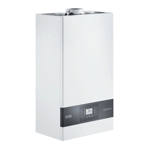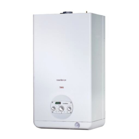
FAMILY CONDENS KIS E
8
If consumption water has a total hardness between 25° F and
50° F, install a DHW treatment kit; with a total hardness great-
er than 50° F, the kit's effectiveness progressively reduces and
therefore the use of an appliance of higher performance or total
softening is recommended; even with a total hardness of less
than 25° F, a filter of appropriate size must be installed if the wa-
ter comes from the mains that is not perfectly clean/cleanable.
A carrying case kit is available that allows to make connections
quickly and without unnecessary waste on each system.
M Heating delivery
AC Hot water outlet
Ggas
R Heating return line
AF Cold water inlet
SC discharge manifold
DISCHARGE MANIFOLD
The discharge manifold collects: condensate water, any evacuation
water from the safety valve and the system discharge water (fig.19).
The manifold must be connected via a pipe (provided) to an ap-
propriate collection and evacuation system in the white water
discharge drain in compliance with current regulations.
Regularly check that the discharge manifold is not blocked by sol-
id residues that might prevent the outflow of condensate water.
The manufacturer is not liable for any damage resulting from
the failure to channel the condensate.
Sealing of the condensate drainage connection line must be
guaranteed.
The boiler manufacturer is not responsible for any floods
caused by the intervention of the safety valves.
3.8 Installing the external probe
The correct operation of the external probe is fundamental for the
good operation of the climatic control.
INSTALLING AND CONNECTING THE EXTERNAL PROBE
The probe must be installed on an external wall of the building to be
heated, observing the following indications:
- it must be mounted on the side of the building most often exposed
to winds (the NORTH or NORTHWEST facing wall), avoiding direct
solar irradiation;
- it must be mounted about 2/3 of the way up the wall;
- it must not be mounted near doors, windows, air outlet points, or
near smoke pipes or other heat sources.
The electrical wiring to the external probe is made with a bipolar ca-
ble with a section from 0.5 to 1 mm2(not supplied), with a maximum
length of 30 metres. It is not necessary to respect the polarity of the
cable when connecting it to the external probe. Avoid making any
joints on this cable however; if joints are absolutely necessary, they
must be watertight and well protected.
Any ducting of the connection cable must be separated from live ca-
bles (230V AC).
FIXING THE EXTERNAL PROBE TO THE WALL
The probe must be fixed on a smooth part of the wall; in the case of
exposed brickwork or an uneven wall, look for the smoothest possi-
ble area (fig.20).
- Loosen the plastic upper protective cover by turning it anticlock-
wise.
- After deciding on the best fixing area of the wall, drill the holes for
the 5x25 wall plug.
- Insert the plug in the hole.
- Remove the card from its seat.
- Fix the box to the wall, using the screw supplied.
- Attach the bracket, then tighten the screw.
- Loosen the nut of the cable grommet, then insert the probe con-
nection cable and connect it to the electric clamp.
To make the electrical connection between the external probe and
the boiler, refer to the “Electrical wiring” chapter.
Remember to close the cable grommet well, to prevent any air
humidity getting in through the opening.
- Put the board back in its seat.
- Close the plastic upper protective cover by turning it clockwise.
Tighten the cable grommet very well.
3.9 Electrical wiring
The FAMILY CONDENS KIS E boiler leaves the factory completely
wired and only need to be connected to the mains power supply (us-
ing the supplied power cable) and the ambient thermostat (TA) and/
or timer, via relevant terminals (fig. 21).
- Set the system's main switch to "off"
- Unscrew the fixing screws of the connections cover (C)
- Take out the connections cover by pulling it towards you (A-B)
- Undo the fixing screws (D) of the shell.
- move the housing base forwards and then upwards to unhook it
from the frame
- Lift the control panel and successively turn it forward
- Unscrew the fixing screws of the terminal board covers, then open
them by sliding them in the direction shown by the arrows.
SPECIAL SYSTEMS
The boiler is able to control an additional circulator connected hy-
draulically as shown in the following diagram (fig. 22).
This way systems with outputs above 1.300 l/h can be managed. The
additional circulator is not supplied, but will have to be chosen by the
installer based on the size of the system. To activate the circulator,
set parameter 20, heating mode, to position 03, additional pump (see
chapter "Parameter Settings" for further details). In these installa-
tions, select the maximum fixed speed mode P90 = 1.
Connect the additional pump in the 2-pole terminal board, in the area
rated for V = 230 volts.
In case of power supply between phases, check with a tester
which of the two wires has a greater potential in relation to the
earth and connect it to the L and similarly connect the remain-
ing wiring to the N.
The boiler can operate with a phase-neutral or phase-phase
supply. For floating power supplies, i.e. that are not connected
to ground/earth at origin, an isolating transformer with earth-an-
chored secondary must be used.
Mandatory items:
- use an omnipolar magnetothermic switch, feeder discon-
nector, compliant with CEI-EN 60335-1 standards (contact
opening of at least 3.5mm, category 3)
- use cables with a section ≥ 1.5mm2and comply with the con-
nection L (phase) - N (Neutral)
- the switch amperage must be adapted to the electric output
of the boiler, refer to technical data to check the electric out-
put of the model installed
- connect the appliance to an effective grounding system
- safeguard access to the power socket after the installation
It is forbidden to use gas and water pipes for grounding the
unit.
The manufacturer is not liable for any damage caused by fail-
ure to comply with the wiring diagrams.
The installer is responsible for ensuring the appliance is suita-
bly earthed; the manufacturer will not be liable for any damage
resulting from an incorrect or absent earth connection.
3.10 Gas connection
The connection of the FAMILY CONDENS KIS E boiler to the gas
supply must be carried out in compliance with current installation
standards.
Before carrying out the connection, it is necessary to ensure that:
- the gas type is suitable for the appliance
- the piping is thoroughly clean.
The gas feeding system must be adapted to the boiler output
and must be equipped with all the safety and control devices
prescribed by the current standards. The use of a filter of ade-
quate dimensions is recommended.
Once the installation is done, check that the junctions carried
out are sealed.
