manuals.online logo
Brands
  1. Home
  2. •
  3. Brands
  4. •
  5. Riello
  6. •
  7. Boiler
  8. •
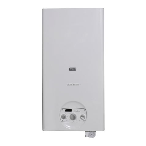
  9. Riello Start Aqua Condens 25 BIS Operation and installation manual

Riello Start Aqua Condens 25 BIS Operation and installation manual

Other manuals for Start Aqua Condens 25 BIS

1

Other Riello Boiler manuals

Riello RTT 378 User manual

Riello

Riello RTT 378 User manual

Riello RBC 1S Series User manual

Riello

Riello RBC 1S Series User manual

Riello INSIEME CONDENS 26 B Instruction Manual

Riello

Riello INSIEME CONDENS 26 B Instruction Manual

Riello 7200 300 HP User guide

Riello

Riello 7200 300 HP User guide

Riello Vokera UNICA MAX Series User manual

Riello

Riello Vokera UNICA MAX Series User manual

Riello RTT Series User guide

Riello

Riello RTT Series User guide

Riello TAU UNIT OIL 35 B Instruction Manual

Riello

Riello TAU UNIT OIL 35 B Instruction Manual

Riello Vokera MAXIM 25 Release note

Riello

Riello Vokera MAXIM 25 Release note

Riello Family KIS Operation and installation manual

Riello

Riello Family KIS Operation and installation manual

Riello GITRE User manual

Riello

Riello GITRE User manual

Riello Steel Pro Power 114-2 P Service manual

Riello

Riello Steel Pro Power 114-2 P Service manual

Riello Residence IN Condens KIS i User manual

Riello

Riello Residence IN Condens KIS i User manual

Riello Caldariello Condens 25 KIS User manual

Riello

Riello Caldariello Condens 25 KIS User manual

Riello Condexa PRO NA 75 P Setup guide

Riello

Riello Condexa PRO NA 75 P Setup guide

Riello Caldariello Condens 25 KIS Operation and installation manual

Riello

Riello Caldariello Condens 25 KIS Operation and installation manual

Riello GITRE LN User manual

Riello

Riello GITRE LN User manual

Riello START KIS Series Operation and installation manual

Riello

Riello START KIS Series Operation and installation manual

Riello INSIEME EVOe 32 V LN User manual

Riello

Riello INSIEME EVOe 32 V LN User manual

Riello ALUDOMUS SOLAR KV/200 20 ISC SOLAR User manual

Riello

Riello ALUDOMUS SOLAR KV/200 20 ISC SOLAR User manual

Riello Caldariello Condens 25 KIS Operation and installation manual

Riello

Riello Caldariello Condens 25 KIS Operation and installation manual

Riello Residence Externa Condens KIS i User manual

Riello

Riello Residence Externa Condens KIS i User manual

Riello Caldariello 24 KIS C Operation and installation manual

Riello

Riello Caldariello 24 KIS C Operation and installation manual

Riello Start Condens 25 IS Operation and installation manual

Riello

Riello Start Condens 25 IS Operation and installation manual

Riello KIS Series Operation and installation manual

Riello

Riello KIS Series Operation and installation manual

Popular Boiler manuals by other brands

IDEAL IMAX XTRA EL 320 user guide

IDEAL

IDEAL IMAX XTRA EL 320 user guide

UTICA BOILERS BC3D Installation, operation & maintenance manual

UTICA BOILERS

UTICA BOILERS BC3D Installation, operation & maintenance manual

Lochinvar SOLUTION 260000 Installation & service manual

Lochinvar

Lochinvar SOLUTION 260000 Installation & service manual

Weil-McLain EG 6 Series manual

Weil-McLain

Weil-McLain EG 6 Series manual

RBI LCD Series Installation & operation manual

RBI

RBI LCD Series Installation & operation manual

Baxi MainEco Combi 28 Installation and service manual

Baxi

Baxi MainEco Combi 28 Installation and service manual

Unical ALKON R 24 Installation and Servicing Manual

Unical

Unical ALKON R 24 Installation and Servicing Manual

Automatic Heating Gasogen Installation and Servicing Manual

Automatic Heating

Automatic Heating Gasogen Installation and Servicing Manual

Viessmann VITORADIAL 300-T Type VR3 Service instructions for contractors

Viessmann

Viessmann VITORADIAL 300-T Type VR3 Service instructions for contractors

Alpha GasSaver GS-1 Installation and servicing instructions

Alpha

Alpha GasSaver GS-1 Installation and servicing instructions

Baxi ROCA LAURA PLUS 28/28 Operating, cleaning and maintenance instructions for the user

Baxi

Baxi ROCA LAURA PLUS 28/28 Operating, cleaning and maintenance instructions for the user

Vaillant uniSTOR VIH SW GB 500 BES operating instructions

Vaillant

Vaillant uniSTOR VIH SW GB 500 BES operating instructions

Kärcher HWE 4000 Gas manual

Kärcher

Kärcher HWE 4000 Gas manual

Radijator BIO max 23.1 instruction manual

Radijator

Radijator BIO max 23.1 instruction manual

Granby BKC Installation, operation and maintenance manual

Granby

Granby BKC Installation, operation and maintenance manual

Brunner BSV 20 Instructions for use

Brunner

Brunner BSV 20 Instructions for use

Potterton 50e Installation and Servicing Manual

Potterton

Potterton 50e Installation and Servicing Manual

UTICA BOILERS TriFire Assembly instructions

UTICA BOILERS

UTICA BOILERS TriFire Assembly instructions

manuals.online logo
manuals.online logoBrands
  • About & Mission
  • Contact us
  • Privacy Policy
  • Terms and Conditions

Copyright 2025 Manuals.Online. All Rights Reserved.

6WDUW$TXD&RQGHQV%,6
EN - INSTALLER AND USER MANUAL
FR - MANUEL D’INSTALLATION ET D’UTILISATION
PT - MANUAL DO USUÁRIO E DO INSTALADOR
HU - TELEPÍTÉSI ÉS HASZNÁLATI KÉZIKÖNYV
GR - ǼīȋǼǿȇǿǻǿȅ ǼīȀǹȉǹȈȉǹȉǾ Ȁǹǿ ȋȇǾȈȉǾ
6WDUW$TXD&RQGHQV%,6
2
6WDUW$TXD &RQGHQV  %,6 boiler complies with basic
requirements of the following Directives:
- Gas Appliance Directive 2009/142/EEC until April 20th
2018 and Regulation (EU) 2016/426 fromApril 21st 2018
- Efficiency directive: Article 7(2) and Annex III of directive
92/42/EEC;
- Electromagnetic compatibility directive 2014/30/EU;
- Low-voltage directive 2014/30/EU;
- Directive 2009/125/EC Ecodesign for energy-using
appliances;
- Directive 2010/30/EU Indication by labelling of the
consumption of energy by energy-related products;
- Delegated Regulation (EU) No. 811/2013;
- Delegated Regulation (EU) No. 813/2013;
- Delegated Regulation (EU) No. 814/2013.
Installer’s - user’s manual...........................................................4
Boiler operating elements.......................................................104
Hydraulic circuit......................................................................106
Electric diagrams....................................................................109
Circulator residual head..........................................................113
(1
The following symbols are used in this manual:
9 &$87,21 =operationsrequiringspecialcareandadequate
preparation
0 127$//2:(' =operationsthatMUSTNOTbeperformed
5$1*(5$7('
This boiler can be adapted to the heating requirements of the system, it is possible to change the maximum output in central heating.
Refer to chapter “Adjustments” for calibration.
After setting the desired output report the value in the table on the back cover of this manual, for future references.
La chaudière 6WDUW$TXD&RQGHQV %,6 respecte les
conditions de base requises par les Règlements suivants:
- Directive Gaz 2009/142/CEE jusqu’au 20 Avril 2018 et
Règlement (UE) 2016/426 depuis 21 Avril 2018;
- Directive Rendement Article 7(2) et Annex III de la
directive 92/42/CEE;
- Directive sur la compatibilité électromagnétique 2014/30/
UE;
- Directive sur la basse tension 2014/35/EU;
- Directive 2009/125/EC concernant les exigences
d’écoconception applicables aux dispositifs d’énergie;
- Directive 2010/30/EU concernant l’étiquetage des
consommations d’énergie des produits liés à l’énergie;
- Règlement Délégué (UE) No. 811/2013;
- Règlement Délégué (UE) No. 813/2013;
- Règlement Délégué (UE) No. 814/2013.
Manuel de l’utilisateur- de l’installateur......................................23
Éléments de fonctionnement de la chaudière .........................104
Circuit hydraulique...................................................................106
Schémas électriques...............................................................109
Hauteur de charge résiduelle ..................................................113
)5
Dans certaines parties du manuel on utilise les symboles:
9 $77(17,21 = actions demandant une certaine prudence
et une préparation adéquate
0 ,17(5',&7,21 = actions NE DEVANT absolument PAS
être exécutées
5$1*(5$7('
Cette chaudière peut être adaptée aux exigences thermiques du système; en effet il est possible de régler la puissance maximale de
la chaudière pour le fonctionnement en mode chauffage. Se référer au chapitre “Réglages” pour consulter les paramètres de réglage.
Une fois que la puissance a été réglée, transférer la valeur dans le tableau présent sur le couvercle arrière. Pour les contrôles et les
réglages ultérieurs, se référer à cette valeur.
A caldeira 6WDUW$TXD&RQGHQV%,6 é compatível com
as especi¿cações básicas das seguintes Diretivas:
Directiva gás 2009/142/CEE até 20 de Abril de 2018 e
Regulamento (UE) 2016/426 de 21 de Abril de 2018
- Diretiva de rendimento: Artigo 7(2) e no Anexo III da
diretiva 92/42/CEE;
- Diretiva de compatibilidade eletromagnética 2014/30/UE;
- Diretiva de baixa tensão 2014/35/UE;
- Diretiva2009/125/CEconcepçãoecológicadosaparelhos
que consomem energia;
- Diretiva 2010/30/UE Indicação por meio de etiquetagem
do consumo energético pelos produtos relacionados com
energia;
- Regulamento Delegado (UE) n.º 811/2013;
- Regulamento Delegado (UE) n.º 813/2013;
- Regulamento Delegado (UE) n.º 814/2013.
Manual do usuário-instalador....................................................43
Elementos de operação da caldeira........................................104
Circuito hidráulico....................................................................106
Diagramas eléctricos...............................................................109
Cabeçal residual do circulador................................................113
37
Em algumas partes do manual são utilizados os símbolos:
9 $7(1d2 = para acções que exigem cautela especial e
preparação adequada
0 352,%,'2 = para acções que NÃO DEVEM absolutamen-
te ser executadas
5$1*(5$7('
Esta caldeira pode ser adaptada às especi¿cações de aquecimento do sistema, é possível modi¿car a saída máxima no aquecimento
central.
Consulte o capítulo “Ajustes” para a calibração.
Após de¿nir a saída desejada, relate o valor na tabela na contracapa deste manual, para consultas futuras.
6WDUW$TXD&RQGHQV%,6
3

6WDUW$TXD&RQGHQV%,6 megfelel az alábbi irányelvek
lényegi követelményeinek:
- Gáz irányelv 2009/142/EGK irányelv 2018. április 20-ig
és 2016/426 / EU rendelet 2018. április 21-tĘl kezdĘdĘe;
- Hatásfok követelményrĘl szóló 92/42/EGK irányelv 7
cikkely (2) és III melléklet;
- 2014/30/EU irányelv az elektromágneses
összeférhetĘségrĘl;
- 2014/30/EU irányelv a kisfeszültségĦberendezésekrĘl;
- 2009/125/EK irányelv az energiafelhasználó termékek
környezetbarát tervezésérĘl;
- 2010/30/EU irányelv az energiával kapcsolatos termékek
energia-fogyasztásának címkézéssel történĘjelölésérĘl;
- 811/2013/EU felhatalmazáson alapuló rendelet;
- 813/2013/EU felhatalmazáson alapuló rendelet;
- 814/2013/EU felhatalmazáson alapuló rendelet.
+8 Telepítési kézikönyv -felhasználói kézikönyv.............................63
A készülék funkcionális részei.................................................104
Vízkeringetés...........................................................................106
Elektromos rajzok....................................................................109
KeringetĘszivattyú maradék emelĘmagassága......................113
ȅȜȑȕȘIJĮȢ 6WDUW$TXD&RQGHQV%,6 ıȣȝȝȠȡijȫȞİIJĮȚ
ȝİ IJȚȢ ȕĮıȚțȑȢ ĮʌĮȚIJȒıİȚȢ IJȦȞ ĮțȩȜȠȣșȦȞ ȅįȘȖȚȫȞ:
- 20 ǹʌȡȚȜȓȠȣ 2018 țĮȚ IJȠȞ țĮȞȠȞȚıȝȩ (ǼǼ) 2016/426 Įʌȩ
IJȘȞ 21ȘǹʌȡȚȜȓȠȣ 2018;
-ȅįȘȖȓĮ ĮʌȩįȠıȘȢ: ȉȠ ȐȡșȡȠ 7 (2) țĮȚ IJȠȣ ʌĮȡĮȡ IJȒȝĮIJȠȢ
III IJȘȢ ȠįȘȖȓĮȢ 92/42/ǼȅȀ;
-ȅįȘȖȓĮ ȘȜİțIJȡȠȝĮȖȞȘIJȚțȒȢ ıȣȝȕĮIJȩIJȘIJĮȢ 2014/30/ǼǼ;
-ȅįȘȖȓĮ ȤĮȝȘȜȒȢ IJȐıȘȢ 2014/35/ǼǼ;
-ȅįȘȖȓĮ 2009/125/ǼȀ ıȤİIJȚțȐ ȝİ IJȠȞ ȠȚțȠȜȠȖȚțȩ ıȤİįȚĮıȝȩ
IJȦȞʌȡȠȧȩȞIJȦȞ ʌȠȣ ıȣȞįȑȠȞIJĮȚ ȝİ IJȘȞ İȞȑȡȖİȚĮ (ErP);
-ȅįȘȖȓĮ 2010/30/ǼǼ īȚĮ IJȘȞ ȑȞįİȚȟȘ IJȘȢ țĮIJĮȞȐȜȦıȘȢ
İȞȑȡȖİȚĮȢ țĮȚ ȜȠȚʌȫȞ ʌȩȡȦȞ IJȦȞ ȠȚțȚĮțȫȞ ıȣıțİȣȫȞ
ȝİ IJȘȞ İʌȚıȒȝĮȞıȘ țĮȚ IJȘȞ ʌĮȡȠȤȒ ȠȝȠȚȩȝȠȡijȦȞ
ʌȜȘȡȠijȠȡȚȫȞ ıȤİIJȚțȐ ȝİ IJĮ ʌȡȠȧȩȞIJĮ;
-ȀĮIJ’İȟȠȣıȚȠįȩIJȘıȘ țĮȞȠȞȚıȝȩȢ (ǼǼ) ǹȡ. 811/2013;
-ȀĮIJ’İȟȠȣıȚȠįȩIJȘıȘ țĮȞȠȞȚıȝȩȢ (ǼǼ) ǹȡ. 813/2013;
-ȀĮIJ’İȟȠȣıȚȠįȩIJȘıȘ țĮȞȠȞȚıȝȩȢ (ǼǼ) ǹȡ. 814/2013.
ǼȖȤİȚȡȓįȚȠ İȖțĮIJȐıIJĮıȘȢ-ǼȖȤİȚȡȓįȚȠ ȤȡȒıȘȢ.............................83
ȈIJȠȚȤİȓĮ ȜİȚIJȠȣȡȖȓĮȢ IJȘȢ ıȣıțİȣȒȢ ..........................................104
ȊįȡĮȣȜȚțȩ țȪțȜȦȝĮ ................................................................106
ǾȜİțIJȡȚțȐ įȚĮȖȡȐȝȝĮIJĮ ...........................................................109
ȊʌȠȜİȚʌȩȝİȞȠ ȪȥȠȢ ȐȞIJȜȘıȘȢ țȣțȜȠijȠȡȘIJȒ ..........................113
*5
Ȉİ țȐʌȠȚĮ ıȘȝİȓĮ IJȠȣ İȖȤİȚȡȚįȓȠȣ ȤȡȘıȚȝȠʌȠȚȠȪȞIJĮȚ IJĮ
ıȪȝȕȠȜĮ:
9 ȆȇȅȈȅȋǾ = ȖȚĮ İȞȑȡȖİȚİȢ ʌȠȣ ĮʌĮȚIJȠȪȞ ȚįȚĮȓIJİȡȘ ʌȡȠıȠȤȒ
țĮȚ țĮIJȐȜȜȘȜȘ ʌȡȠİIJȠȚȝĮıȓĮ
0 ǹȆǹīȅȇǼȊǼȉǹǿ = ȖȚĮ İȞȑȡȖİȚİȢ ʌȠȣ ǻǼȃ ȆȇǼȆǼǿ ȞĮ țȐ-
ȞİIJİ ıİ țĮȝȓĮ ʌİȡȓʌIJȦı
5$1*(5$7('
ȅȜȑȕȘIJĮȢ ĮȣIJȩȢ ȝʌȠȡİȓ ȞĮ ʌȡȠıĮȡȝȠıIJİȓ ıIJȚȢ ĮʌĮȚIJȒıİȚȢ șȑȡȝĮȞıȘȢ IJȠȣ ıȣıIJȒȝĮIJȠȢ ȆȡȐȖȝĮIJȚ, ȝʌȠȡİȓ ȞĮ ȡȣșȝȚıIJİȓ ȘȝȑȖȚıIJȘ ʌĮȡȠȤȒ
IJȠȣ ȜȑȕȘIJĮ ȖȚĮ IJȘ ȜİȚIJȠȣȡȖȓĮ șȑȡȝĮȞıȘȢ. ǹȞĮIJȡȑȟIJİ ıIJȠ țİijȐȜĮȚȠ “ȇȣșȝȓıİȚȢ” ȖȚĮ IJȚȢ ȡȣșȝȓıİȚȢ ȕĮșȝȠȞȩȝȘıȘȢ.
ǹijȠȪ İʌȚȜİȤșİȓ ȘİʌȚșȣȝȘIJȒ ȚıȤȪȢ ȝİIJĮijȑȡİIJİ IJȘȞ IJȚȝȒ ıIJȠȞ ʌȓȞĮțĮ ʌȠȣ ʌĮȡȑȤİIJĮȚ ıIJȠ ʌȓıȦ țĮʌȐțȚ.
īȚĮ IJȠȣȢ İʌȩȝİȞȠȣȢ İȜȑȖȤȠȣȢ țĮȚ ȡȣșȝȓıİȚȢ, ĮȞĮIJȡȑȤİIJİ ʌȐȞIJĮ ıIJȘȞ İʌȚȜİȖȝȑȞȘ IJȚȝȒ.
A kézikönyvben az alábbi szimbólumok szerepelnek:
9 ),*<(/(0 = megfelelĘkörültekintést és felkészülést
igénylĘtevékenységek
0 7,/26 = olyan tevékenységek, amelyeket NEM SZABAD
végrehajtani
5$1*(5$7('
Abojlera rendszer fĦtésiigényeihezigazítható.Aközponti fĦtés maximálisteljesítményemódosítható.Abeállításhoz lásda“Szabályozás”
részt.
A megfelelĘteljesítmény beállítása után jegyezze fel az értéket a kézikönyv hátsó borítóján lévĘtáblázatba
6WDUW$TXD&RQGHQV%,6
4
(1 (1*/,6+
,167$//$7,210$18$/
 :$51,1*6$1'6$)(7<
9 After removing the packaging, check the integrity and
completeness of the supply and, otherwise, contact the Riello
Agency that sold the boiler.
9 The 6WDUW$TXD&RQGHQV%,6boiler must be installed by a
quali¿ed company in accordance with the regulations in force,
attheendofthe installationprocess, mustissuetheownerwith
a declaration of conformity certifying that the installation has
been performed according to the best working practices and
in observance of applicable legislation and of the indications
provided by Riello in the present instructions booklet.
9 The installer must instruct the user about the operation of the
appliance and about essential safety regulations.
9 When carrying out routine maintenance, it is always
recommended to check the consumption level of the sacri¿cial
anode.
9 The boiler must be used for the purpose for which it was
expressly built. The manufacturer accepts no liability within or
withoutthe contract foranydamagecaused to people,animals
and property due to installation, adjustment and maintenance
errors or to improper use.
9 In the event of a water leakage, shut off the water supply and
promptly contact the Technical Assistance Centre or other
professionally quali¿ed personnel.
9 Not using the boiler for an extended period of time involves
the execution of at least the following operations:
- turn the main appliance switch and the main system switch
to "off"
- close the fuel and water taps of the heating system
- drain the heating and domestic hot water circuits if there is
a risk of freezing.
9 The boiler maintenance must be carried out at least once a
year.
9 This booklet and that of the User are an integral part of the
appliance and therefore should be carefully preserved and
should always accompany the boiler even when it is sold to
another owner or user or when transferred to another system.
In case of loss or damage, please contact your local Technical
Assistance Centre for a new copy.
9 This appliance should not be operated by children younger
than 8 years, people with reduced physical, sensory or men-
tal capacities, or inexperienced people who are not familiar
with the product, unless they are given close supervision or
instructions on how to use it safely and are made aware by a
responsible person of the dangers its use might entail. Chil-
dren must not play with the appliance. It is the user’s respon-
sibility to clean and maintain the appliance. Children should
never clean or maintain it unless they are given supervision.
9 The boiler is constructed so as to protect both the user and
the installer from any accidents.After each intervention on the
product, pay special attention to the electrical connections,
especially the stripped parts of the wires, which must not
protrude from the terminal board in any way.
9 Dispose of all the packaging materials in the suitable
containers at the corresponding collection centres.
9 When disposing of waste, be careful not to harm human
health or employ procedures or methods which may damage
the environment.
At the end of its life, the product should be not be disposed of
as solid urban waste, but rather it should be handed over to a
differentiated waste collection centre.
Remember that the use of products requiring fuels, electricity and
water necessitates the respect of certain basic safety rules
such as:
0 it is forbidden to activate electric devices or appliances such
as switches, household appliances and so on if you notice a
smell of fuel or unburnt fuel;
0 in this case:
- ventilate the room by opening the doors and windows
- close the fuel shut-off device
- promptly call the Technical Assistance Centre or
professionally qualified personnel;
0 it is forbidden to touch the boiler while barefoot or if parts of
your body are wet;
0 it is forbidden to carry out any cleaning operations before
disconnecting the boiler from the electricity supply; to do this,
turn the main system switch to “OFF”;
0 it is forbidden to modify safety and adjustment devices without
the boiler manufacturer's permission and relative instructions;
0 it is forbidden to pull, detach or twist the electric cables that
emerge from the boiler, even if the boiler itself is disconnected
from the mains supply;
0 it is forbidden to plug or reduce the size of any openings used
for airing the installation area;
0 it is forbidden to leave Àammable containers and substances
in the room where the boiler is installed;
0 it is forbidden to disperse and leave packaging material within
children's reach as it may be a potential source of hazard;
0 it is forbidden to obstruct the condensate outlet.
 '(6&5,37,21
6WDUW$TXD&RQGHQV%,6 is a wall-hung condensing boiler, with
premix burner and low emission of pollutants for heating and for the
production of DHW use and has a 45 litre steel storage tank.
This is an electronically controlled boilers with automatic ignition,
ionisation flame check and with proportional control system of the
gas and air flows, both in heating and DHW.
It uses an aluminium alloy boiler body, has a sealed combustion
chamber and, based on the gas discharge accessory used, is
classified in categories B23P, B53P, C13-C13x, C33-C33x, C43-
C43x, C53-C53x, C83-C83xC93C93x. The switching of the heating
and DHW modes is performed via a three-way electric valve which
set on DHW when in the rest position. To guarantee the correct
water output in the exchanger, the boiler is equipped with an
automatic by-pass.
The 6WDUW$TXD&RQGHQV%,6 boiler is also equipped with:
- Range Rated - this means the boiler is equipped with a device
that adapts it to the heat requirements of the system, so the
boiler output can be adjusted according to the energy needs of
the building.
- Circulator anti-blocking.
- First-level antifreeze (suitable for indoor installations).
- 8 litre expansion tank.
- 2 litre DHW expansion tank.
- Digital display indicating the operating temperature and alarm
codes.
- Pre-mix low emissions burner.
- Continuous electronic flame modulation for domestic hot water
and heating.
(1*/,6+
5
- Premix combustion system which ensures a constant air-gas
ratio.
- Anti-legionella: Legionella is a disease that can be contracted
by inhaling small droplets of water (aerosols) which contain the
Legionella bacteria (bacteria occurs naturally in lakes and rivers
all over the world). The decimation of the bacterium is obtained
by taking the stored water to a temperature over 50/55° C.
It is therefore recommended to position the DHW temperature
selection knob to maximum at least every 2/3 days, taking the
temperature of the stored water to 60° C, and maintaining this
temperature for a minimum time of 5 minutes.
- Ambient thermostat or programmable timer, remote control or
local valve prearrangement.
- Provision for external probe connection that enables the climate
control function.
- Prepared for limit thermostat on reduced temperature systems.
- Self-diagnostics for signalling the cleaning of the primary circuit
heat exchanger.
 6DIHW\GHYLFHV
The 6WDUW $TXD &RQGHQV  %,6 boiler is equipped with the
following safety devices:
 6DIHW\YDOYH that intervenes in the event of excessive hydraulic
pressure (max 3 bar).
 :DWHU FLUFXLW GLDJQRVLV which safeguards the boiler in the
event of insufficient circulation or lack of water. The electronics
of the boiler, by comparing the temperature read by the outlet
and return sensors (circulation analysis) and the rise rate of
the output temperature (no water analysis) ensures the safety
lockout of the appliance.
 )OXHJDVSUREH: this intervenes (putting the boiler in safety stop
mode) if the temperature of the combustion products exceeds
the maximum operating temperature of the discharge pipes.
 )OXH JDV VDIHW\ HYDFXDWLRQ V\VWHP incorporated in the
pneumatic operation of the gas valve subject to the premix
burner. The gas valve is opened based on the quantity of air
pushed by the fan. This implies that, if the flue gases exhaust
circuit is blocked, the air flow is cancelled and the valve does
not have the ability to open. Furthermore, the float present in
the siphon prevents any passage of the flue gases from the
condensation discharge.
 &RQGHQVDWH GLVFKDUJH REVWUXFWLRQ VDIHW\ GHYLFH that
via a condensate level sensor blocks the boiler if the level of
condensate in the heat exchanger exceeds the limit allowed.
 2YHUWHPSHUDWXUHVDIHW\GHYLFHon both the delivery and return
lines, with dual probe (limit temperature 95°C).
9 The intervention of the safety devices indicates a boiler
malfunction, therefore immediately contact the Technical
Assistance Centre.
9 The boiler must not be put in service, even temporarily, with
non-operating or tampered safety devices.
9 The safety devices must be replaced by the Technical
Assistance Centre, using exclusively original manufacturer
components.
After carrying out the repair, perform an ignition test.
 &LUFXODWRU
The residual discharge head for the heating system in terms of flow
rate is outlined in the graph (fig. 1-2).
The heating system pipes must be dimensioned bearing in mind
the residual discharge head available.
Note that the boiler is working properly if the heat exchanger for
heating has sufficient water circulation.
For this reason, the boiler is fitted with an automatic by-pass that
sets the correct flow rate for the water in the heat exchanger for
heating in any system condition.
The boilers are equipped with an anti-blocking system which starts
up an operation cycle after every 24 hours of stop, with the mode
selector in any position.
9 The "anti-locking" function is only activated when the boiler is
electrically powered.
0 It is strictly forbidden to operate the circulator without water.
 ,167$//$7,21
 5HFHLYLQJWKHSURGXFW
The 6WDUW$TXD&RQGHQV%,6 boiler is supplied in a single pack
protected by cardboard packaging.
The boiler is supplied as standard with the following material:
- instruction booklet for the installer and user
- bar code labels
- supporting cross-member
- package with hydraulic fittings.
9 The instruction booklets are an integral part of the boiler and
there it is recommended to read them carefully and keep them
in a safe place.
 'LPHQVLRQVDQGZHLJKWVILJ
6WDUW$TXD&RQGHQV%,6
L 600 mm
P450mm
H 940 mm
net weight 66 kg
 +DQGOLQJ
After unpacking, handling of the boiler is done manually using the
support frame (fig. 4).
 ,QVWDOODWLRQURRP
In configuration C, the appliance can be installed in any type of
room and there are no limitations due to ventilation conditions
or room volume since the 6WDUW $TXD &RQGHQV  %,6 boiler
has an "airtight" combustion circuit in relation to the installation
environment.
In configuration B23P, B53P the appliance cannot be installed in
bedrooms, bathrooms, showers or where there are open fireplaces
without a proper air flow. The room where the boiler is installed
must have proper ventilation.
9 Consider the clearances necessary to access safety and
adjustment devices and to perform maintenance operations.
9 Check that the electric protection level of the appliance is
suitable for the installation room characteristics.
9 If the boilers are supplied with fuel gas of a speci¿c weight
greater than that of the air, the electric parts will have to be
positioned more than 500mm above ground level.
 ,QVWDOODWLRQRQDSSOLDQFHVWKDWDUHROGRUWKDW
QHHGWREHXSGDWHG
When the 6WDUW$TXD&RQGHQV  %,6 boiler is installed in old
systems or systems being updated, verify that:
- The smoke pipe is suitable for the temperature of the combustion
products with condensation, calculated and built according to
Standard, is as straight as possible, airtight, insulated and has
no blockages or narrow sections. It is equipped with appropriate
condensate collection and discharge systems
- The electrical system is installed in compliance with the specific
standards and by qualified personnel
- The fuel supply line and eventual tank (LPG) are made according
to specific Standards
- The expansion tank ensures the total absorption of the dilatation
of the fluid contained in the system
- The flow rate and head of the circulator are suitable to the
characteristics of the system.
- The system has been washed and cleaned of mud and grime, de-
aerated and water tight. It is recommended to install a magnetic
filter on the return of the system.
- The boiler condensate drain system (siphon) is connected and
routed to the collection of "white" water.
6WDUW$TXD&RQGHQV%,6
6
9 The manufacturer is not liable for any damage resulting from
the incorrect construction of the Àue gas discharge system.
9 The Àue gas discharge pipes for condensing boilers are made
of special materials that are different compared to those made
for standard boilers.
 %RLOHULQVWDOODWLRQ
For correct installation, keep in mind that (fig. 5):
- the boiler must not be placed above a stove or other cooking
appliance
- it is forbidden to leave inflammable products in the room where
the boiler is installed
- heat-sensitive walls (e.g. wooden walls) must be protected with
proper insulation
- the minimum clearances for technical and maintenance
interventions must be respected.
The boiler is supplied with a pre-assembly template which allows
for realising the connections to the heating and domestic hot water
system without the boiler, which may be subsequently assembled,
standing in the way.
Connect the discharge manifold to a suitable discharge system (for
details, see chapter "Discharge manifold").
),;,1*2)7+(35($66(0%/<7(03/$7(
The 6WDUW$TXD&RQGHQV%,6 boiler is designed and built to be
installed in heating and domestic hot water systems.
The position and dimension of hydraulic fittings are shown in the
drawings (fig. 6).
- Position the plate with the aid of a spirit level: check the correct
horizontal plane and the planarity of the boiler rest surface; make
it thicker if needed.
- Trace the fixing points.
- Remove the template and carry out the drilling.
- Fix the plate to the wall using appropriate plugs.
- Check the correct horizontality with a spirit level.
),;,1*7+(%2,/(5
- Hook the boiler to the brackets on the plate.
 +\GUDXOLFFRQQHFWLRQVILJ
Connect the fittings and gaskets supplied with the system.
We recommend connecting the boiler to the systems introducing
both the DHW shut-off valve as well as the shut-off valves for the
heating system; for this purpose a heating system valves kit and
heating valves kit with filter is available.
Connect brass taps supplied to the fittings and the boiler.
9 Theselectionandtheinstallationofthesystemcomponentsare
the responsibility of the installer, who must operate according
to the rules of good technique and current Legislation.
9 Acarrying case kit is available that allows to make connections
quickly and without unnecessary waste on each system.
0 Heating delivery 3/4”
5 Heating return line 3/4”
*Gas 3/4”
6& Discharge manifold
$) Cold water inlet 1/2”
$& Hot water outlet 1/2”
 'LVFKDUJHPDQLIROG
The discharge manifold collects: condensate water, any evacuation
water from the safety valve and the system discharge water (fig. 10).
9 The manifold must be connected via a rubber pipe (not
provided) to an appropriate collection and evacuation system
in the white water discharge drain in compliance with current
regulations. The outer diameter of the manifold is 20 mm: it is
therefore advisable to use a rubber pipe ø18-19 mm closed
with a suitable clamp (not provided).
9 Regularly check that the discharge manifold is not blocked by
solid residues that might prevent the outÀow of condensate
water.
9 The manufacturer is not liable for any damage resulting from
the failure to channel the condensate.
9 Sealing of the condensate drainage connection line must be
guaranteed.
9 The boiler manufacturer is not responsible for any Àoods
caused by the intervention of the safety valves.
 ,QVWDOOLQJWKHH[WHUQDOSUREHDFFHVVRU\
The correct operation of the external probe is fundamental for the
good operation of the climatic control.
,167$//,1*$1'&211(&7,1*7+((;7(51$/352%(
The probe must be installed on an external wall of the building to be
heated, observing the following indications:
- itmustbemountedon the side of the building most often exposed
to winds (the NORTH or NORTHWEST facing wall), avoiding
direct solar irradiation;
- it must be mounted about 2/3 of the way up the wall;
- it must not be mounted near doors, windows, air outlet points, or
near smoke pipes or other heat sources.
The electrical wiring to the external probe is made with a bipolar
cable with a section from 0.5 to 1 mm2(not supplied), with a
maximum length of 30 metres. It is not necessary to respect the
polarity of the cable when connecting it to the external probe.Avoid
making any joints on this cable however; if joints are absolutely
necessary, they must be watertight and well protected.
Any ducting of the connection cable must be separated from live
cables (230V AC).
),;,1*7+((;7(51$/352%(727+(:$//
The probe must be fixed on a smooth part of the wall; in the case
of exposed brickwork or an uneven wall, look for the smoothest
possible area (fig. 11).
- Loosen the plastic upper protective cover by turning it
anticlockwise.
- After deciding on the best fixing area of the wall, drill the holes
for the 5x25 wall plug.
- Insert the plug in the hole.
- Remove the card from its seat.
- Fix the box to the wall, using the screw supplied.
- Attach the bracket, then tighten the screw.
- Loosen the nut of the cable grommet, then insert the probe
connection cable and connect it to the electric clamp.
To make the electrical connection between the external probe and
the boiler, refer to the “Electrical wiring” chapter.
9 Remember to close the cable grommet well, to prevent any air
humidity getting in through the opening.
- Put the board back in its seat.
- Close the plastic upper protective cover by turning it clockwise.
Tighten the cable grommet very well.
 (OHFWULFDOZLULQJ
The 6WDUW $TXD &RQGHQV  %,6 boiler leaves the factory
completely wired and only need to be connected to the mains
power supply (using the supplied power cable) and the ambient
thermostat (TA) and/or timer, via relevant terminals.
- Set the system's main switch to "off"
- Loosen the screws (%) that hold the housing in place (fig. 12)
- Move the base of the shell forward and then upwards in order to
free it from the frame (fig. 13)
- Turn the instrument panel forward
- Unscrew the two screws of the small cover on the electronic
board to have access to the terminals (fig. 14).
9 Safety low voltage ambient thermostat input (clean contact).
9 In case of power supply between phases, check with a tester
which of the two wires has a greater potential in relation to
(1*/,6+
7
the earth and connect it to the L and similarly connect the
remaining wiring to the N.
9 The earth conductor must be a couple of cm longer than the
others.
9 The boiler can operate with a phase-neutral or phase-phase
supply.
9 Mandatory items:
- use an omnipolar magnetothermic switch, feeder
disconnector, compliant with CEI-EN 60335-1 standards
(contact opening of at least 3.5mm, category 3)
- use cables with a section 1.5mm2and comply with the
connection L (phase) - N (Neutral)
- the switch amperage must be adapted to the electric output
of the boiler, refer to technical data to check the electric
output of the model installed
- connect the appliance to an effective grounding system
- safeguard access to the power socket after the installation
0 It is forbidden to use gas and water pipes for grounding the
unit.
9 The manufacturer is not liable for any damage caused by
failure to comply with the wiring diagrams.
9 The installer is responsible for ensuring the appliance is
suitably earthed; the manufacturer will not be liable for any
damageresultingfromanincorrectorabsentearthconnection.
 %RLOHUFRQILJXUDWLRQ
The electronic board has a number of jumpers (JPX) that allow to
configure the boiler.
To access the board, proceed as follows:
- set the main system switch to OFF
- loosen the screws (%) that hold the housing in place (fig. 12)
- move the base of the shell forward and then upwards in order to
free it from the frame (fig. 13)
- turn the instrument panel forward
- unscrew the two screws of the small cover on the electronic
board to have access to the terminals (fig. 14).
-803(5 -3: pre-selection of the most appropriate heating
temperature adjustment field based on the type of system.
-XPSHUQRWLQVHUWHGVWDQGDUGV\VWHP standard system 40-80 °C
-XPSHULQVHUWHGIORRUV\VWHP: floor installation 20-45°C.
During manufacture, the boiler is configured for standard systems
(fig. 15).
JP1 Calibration (Range Rated)
JP2 Heating timer reset
JP3 Calibration (see paragraph “Adjustments”)
JP4 Jumper on. Do not modify.
JP5 Jumper on. Do not modify.
JP6 Enable night-time compensation and continuous pump
function (only with outdoor probe connected)
JP7 Enable standard system/low temperature
management (see above)
JP8 No jumper. Do not modify.
 *DVFRQQHFWLRQ
Theconnectionof the 6WDUW$TXD&RQGHQV%,6 boiler to the gas
supply must be carried out in compliance with current installation
standards.
Before carrying out the connection, it is necessary to ensure that:
- the gas type is suitable for the appliance
- the piping is thoroughly clean.
9 The gas feeding system must be adapted to the boiler output
and must be equipped with all the safety and control devices
prescribed by the current standards. the use of a ¿lter of
adequate dimensions is recommended.
9 Once the installation is done, check that the junctions carried
out are sealed.
 )OXH JDV RXWOHW DQG FRPEXVWLRQ DLU VXFWLRQ ILJ

The 6WDUW$TXD&RQGHQV  %,6 boiler must be equipped with
adequate flue gas outlet and air suction pipes according to the
type of installation, to be chosen from those indicated in the Riello
catalogue.
9 For the maximum lengths of the ducts refer to Àue systems
available in the catalogue.
9 The straight length measurement is inclusive of the ¿rst bend
(boiler connection), terminals and joints; with the exception
of the vertical coaxial duct Ø 60-100 mm, where the straight
length does not include the bends.
9
7<3(%3%3,167$//$7,21
)OXHJDVGLVFKDUJHSLSH¡PP
The flue gas outlet pipe can be directed to the most suitable
direction according to installation requirements.
For installation, follow the instructions supplied with the kit.
In this configuration, the boiler is connected to the flue gas outlet
pipe of ø 80 mm through an adaptor of ø 60-80 mm.
9 In this case, the combustion air is picked up from the boiler
installation room (which must be a suitable technical room
with proper ventilation).
9 The non insulated Àue gas outlet pipes are potential sources
of danger.
9 Make sure the Àue gas discharge pipe is tilted 3° towards the
boiler.
PD[LPXPOHQJWKRIWKHIOXHJDV
GLVFKDUJHSLSH¡PP
SUHVVXUHGURS
FXUYHFXUYH
60 m 1 m 1,5m
9 "Straight length" means without bends, drainage terminals or
joints.
³$,57,*+7´,167$//$7,217<3(&
The boiler must be connected to concentric or twin flue gas
discharge pipes and air suction pipes, both leading outdoors. The
boiler must not be operated without them.
&RQFHQWULFSLSHV¡PP
The concentric pipes can be fitted in most suitable direction in
relation to installation requirements.
9 It is compulsory to use speci¿c pipes (see Riello catalogue).
9 Make sure the Àue gas discharge pipe is tilted 3° towards the
boiler.
9 Non-insulated outlet pipes are potential sources of danger.
9 The boiler automatically adapts ventilation according to the
type of installation and the length of the duct. Do not obstruct
or choke the combustion air suction pipe in any way.
+25,=217$/
VWUDLJKWOHQJWKRIFRQFHQWULF
SLSHPP
SUHVVXUHGURS
FXUYHFXUYH
7,85 m 1,3m 1,6m
9(57,&$/
VWUDLJKWOHQJWKRIFRQFHQWULF
SLSHPP
SUHVVXUHGURS
FXUYHFXUYH
8,85 m 1,3m 1,6m
For installation, follow the instructions supplied with the speci¿c
6WDUW$TXD&RQGHQV%,6
8
accessory kit for condensing boilers.
9 Straight length means without bends, drainage terminals or
joints.
9 The use of a longer pipe causes a loss of output of the boiler.
&RQFHQWULFSLSHV¡
The appropriate adaptor kit must be installed for this configuration.
The concentric pipes can be fitted in most suitable direction in
relation to installation requirements. For installation, follow the
instructions supplied with the specific kit for condensing boilers.
VWUDLJKWOHQJWKRIFRQFHQWULF
SLSHPP
SUHVVXUHGURS
FXUYHFXUYH
14,85 m 1 m 1,5m
9 "Straight length" means without bends, drainage terminals or
joints.
7ZLQSLSHV¡PP
Thetwinpipescanfaceinthedirectionmostsuitedtotheinstallation
requirements.
The suction pipe of the combustion air must be connected to the
input after removing the cap fixed with three screws.
The flue gases discharge pipe must be connected to the flue gases
outlet.
For installation, follow the instructions supplied with the specific
accessory kit for condensing boilers.
VWUDLJKWOHQJWKRIWZLQSLSHV¡PP SUHVVXUHGURS
FXUYHFXUYH
36+36 m 1 m 1,5m
9 "Straight length" means without bends, drainage terminals or
joints.
9 The use of a longer pipe causes a loss of output of the boiler.
9 It is compulsory to use speci¿c pipes (see Riello catalogue).
9 Make sure the Àue gas discharge pipe is tilted 3° towards the
boiler.
9 The boiler automatically adapts the purging to the type of
installation and the length of the pipes. Do not obstruct or
choke the pipes in any way.
9 For the indication of the maximum lengths of the single pipe,
refer to the charts.
3266,%/(287/(7&21),*85$7,216¿J
%3%3 Suction in room, with external outlet
&&[ Concentric wall outlet. The pipes may also be split,
but the outputs must be concentric or sufficiently
close together to be subjected to similar wind con-
ditions (within 50cm)
&&[ Concentric roof outlet. Outlets as for C13
&&[ Discharge and suction in separate shared smoke
pipes subject to similar wind conditions
&&[ Separated discharge and suction on wall or roof,
in areas with different pressure levels
&&[ Outlet in single or shared smoke pipe and wall
suction line.
&&[ Discharge on roof (similar to C33) and air suction
via a single existing smoke pipe.
9 Refer to the regulations in force.
 6\VWHPORDGLQJDQGHPSW\LQJILJ
),//,1*7+(6<67(06
In case of a new installation or replacement of the boiler, it is
necessary to clean the heating system.
In order to ensure the proper functioning of the product, after any
cleaning, additive and/or chemical treatments (e.g. antifreeze
liquids, filming agents, etc.) check that the parameters in the table
are within the indicated values.
3DUDPHWHUV XQLWRI
PHDVXUHPHQW
+RWZDWHU
FLUFXLW
)LOOLQJ
ZDWHU
pH value - 7-8 -
Hardness °F - <15
Appearance - - clean
Fe mg/kg 0,5 -
Cu mg/kg 0,1 -
Once the hydraulic connections have been carried out, fill the
system. This operation must be carried out with a cold system,
following these instructions:
'RPHVWLFKRWZDWHUV\VWHP
- open the cold water inlet tap to fill the storage tank
- to check that the storage tank is full, open a hot water tap and
wait for the water to exit.
+HDWLQJV\VWHP
- make sure that the system discharge valve (%) is closed
- open the plug of the automatic bleed valves (&and () by two or
three turns
- open the filling tap (*) until the pressure indicated by the water
pressure gauge is 1,5 bar.
- open the manual bleed valve (') with a CH11 wrench and close
it once the bleeding procedure is completed; If necessary, repeat
this operation until no more air exits the valve (')
- once the filling operation of the system is finished, close the filling
tap *
Each time the boiler is electrically powered, it begins an automatic
venting cycle that lasts about 2 minutes. The symbol “ ” is
displayed during this phase.
127(the venting of the boiler takes place automatically via the
two automatic bleed valves &and (.
127(the first system filling operation must be done by means of
tap *.
(037<,1*7+(6<67(06
Before starting emptying, switch off the electrical supply by turning
off the system's main switch
+HDWLQJV\VWHP
- close the shut-off
devices of the heating system
- open the automatic bleed valve (&)
- manually loosen the system drain valve (%), keeping the elbow of
the hose in position to prevent it slipping from its seat
- the system's water is discharged through the discharge manifold ($)
- drain the lowest points of the system.
'RPHVWLFKRWZDWHUV\VWHP
When there is risk of frost, the domestic hot water system must be
emptied in the following way:
- turn off the main water supply tap
- unscrew the plug on the hose connection ())
- connect a plastic pipe to the hose connection of the storage tank
discharge valve ())
- release the discharge device of the valve
- turn on all the hot and cold water taps
- drain the lowest points of the system.
9 The discharge manifold ($) must be connected via a rubber
pipe to an appropriate collection and evacuation system in
the white water discharge drain in compliance with current
regulations. The outer diameter of the manifold is 20 mm: it is
therefore advisable to use a rubber pipe Ø18-19 mm closed
with a suitable clamp (not provided). The manufacturer is not
liable for any damage resulting from the failure to channel the
condensate.
(OLPLQDWLQJWKHDLUIURPWKHKHDWLQJFLUFXLWDQGERLOHUILJ
Duringtheinitial installationphase,orinthe eventofamaintenance,
you are advised to perform the following sequence of operations:
- Switch off the power supply to the boiler.
(1*/,6+
9
- Using a CH11 spanner open the manual air vent valve located
above the air box; the tube supplied with the boiler must be
connected to the valve to let out the water into an outside
container.
- Turn on the system filling tap on the hydraulic unit and wait until
the water starts coming out of the valve. Make sure that it comes
only water.
- Close the manual air vent valve with the CH11 spanner.
- Turn off the system filling tap when the water pressure indicated
by the hydrometer reaches 1-1.5 bar.
- Switch on the power supply to the boiler leaving the boiler in OFF
mode. Check that the gas tap is closed.
- The boiler, now, starts the vent cycle. Perform it by checking
that there is no air inside the boiler and that the pressure does
not drop too much (otherwise repeat the operations described
above).
- Turn on the gas tap and ignite the boiler.
 &200,66,21,1*$1'0$,17(1$1&(
 )LUVWFRPPLVVLRQLQJSUHSDUDWLRQ
Before the ignition and the functional testing of the 6WDUW $TXD
&RQGHQV%,6boiler, it is necessary to:
- check that the system fuel and water supply taps are open
- check that the gas type and the power supply pressure are those
for which the boiler is designed
- make sure the cap on the vent valve is open
- check on the display that the pressure of the water circuit when
cold is between 1 bar and 1.5 bar and that the circuit is vented
- check that the pre-loading of the expansion tank is adequate
(see the "Technical data" table)
- check that the electrical connections have been carried out
correctly
- check that the combustion product outlet and air suction pipes
were adequately realised
- check that the circulator turns freely; undo the inspection screw
and check with a flat screwdriver that the rotor shaft moves
without hindrances.
9 Before loosening or removing the closing tap of the circulator,
protect the underlying electrical devices from possible water
leakage.
 &RQWUROSULRUWRFRPPLVVLRQLQJ
9 The ¿rst time you turn the boiler on and in case of maintenan-
ce work, before using the appliance you must ¿ll the siphon
with water and make sure that the condensation is evacuated
correctly.
Fill the condensation collection siphon pouring 1 litre of water into
the boiler combustion-analysis outlet with the boiler off, and check
that:
the safety cut-off device is Àoating
water is Àowing correctly from the discharge pipe out of the boiler
the condensate outlet connection line is watertight.
If the condensate outlet circuit (siphon and pipes) is working cor-
rectly, the condensation level will not exceed the maximum.
Filling the siphon before using the appliance, and the use of a sa-
fety cut-off device inside the siphon, prevent exhaust gases from
being released into the environment.
Repeat during standard and non-standard maintenance work.
~15 mm
MAX
- Adjust the ambient temperature thermostat to the desired
temperature (~20°C) or, if the system is equipped with a
programmable thermostat or timer, ensure that the thermostat or
timer is "active" and set correctly (~20°C)
- A variety of information appears on the display for each power
supply, including the value of the flue gases probe meter (-C- XX
- see "Display and fault codes" - Fault A 09), the boiler will then
start an automatic venting cycle of about 2 minutes
- The display shows the symbol
To stop the automatic venting cycle, proceed as follows:
- access the electronic board by removing the housing, turning the
instrument panel forwards you and opening the terminal board
cover.
Then:
- press the CO button.
9 Live electrical parts (230 Vac).
CN6 CN5
CN12
1
JP1
JP2
JP3
JP4
JP5
JP6
JP7
JP8
CN15
P3 P2
P1
CN13
CN14
SW1
P4
&2EXWWRQ
To start up the boiler it is necessary to carry out the following
operations:
- power the boiler
- turn on the gas tap to allow fuel flow
- adjust the ambient thermostat to the required temperature
(~20°C).
Turn the mode selector to the required position:
:LQWHUPRGH
Turn the function selector to within the adjustment range. The
boiler produces domestic hot water and heating water. The boiler
lights automatically in response to a heat request. The digital
display indicates the heating water temperature. The boiler lights
automatically in response to a request for domestic hot water. The
display indicates the domestic hot water temperature.
6WDUW$TXD&RQGHQV%,6
10
:,17(502'(
$GMXVWPHQWRIWKHKHDWLQJZDWHUWHPSHUDWXUH
To adjust the heating water temperature, turn the mode selector to
within the adjustment range (turn clockwise to increase the value
and anticlockwise to reduce the value).
Depending on the type of system, the most suitable temperature
range can be pre-selected:
- standard systems 40-80 °C
- floor installations 20-45°C.
For details see paragraph “Boiler configuration”.
+($7,1*:$7(5
7(03(5$785(
'20(67,&+27:$7(5
7(03(5$785(
$GMXVWLQJ WKH KHDWLQJ ZDWHU WHPSHUDWXUH ZLWK DQ H[WHUQDO
SUREHFRQQHFWHG
When an external probe is installed, the delivery temperature
is automatically selected by the system, which quickly adjusts
the ambient temperature according to variations in the outside
temperature. If you want to alter the temperature value (increasing
or reducing the value automatically calculated by the electronic
card), use the heating water temperature selector: turn it clockwise
to increase the temperature, or anticlockwise to reduce it.
The correction possibility is between 15° C and 25° C levels of
comfort (0 = 20° C), shown on the digital display by rotating the
knob.
6XPPHUPRGH
The standard domestic hot water-only mode is activated by
turning the selector to the summer symbol . The boiler lights
automatically in response to a request for domestic hot water. The
digital display indicates the delivery temperature.
6800(502'(
$GMXVWPHQWRIWKHGRPHVWLFKRWZDWHUWHPSHUDWXUH
To adjust the domestic hot water temperature (for baths, showers,
kitchen etc.), turn the dial with the symbol clockwise to increase
the value, or anticlockwise to decrease the value (min. value 37°C -
max. value 60 °C). The boiler is in standby until the burner switches
on following a heat request. The boiler continues to function until
the temperatures set on the boiler are reached, or the heat request
terminates;it willthengobackto standby.In thecaseof atemporary
stop the digital display shows the fault code.
$'-867,1*7+('20(67,&+27:$7(57(03(5$785(
+HDWLQJ7HPSHUDWXUH&RQWUROIXQFWLRQ&75
Turn the heating water temperature selector into sector highlighted
with white markers to activate the C.T.R. self-adjusting system:
depending on the temperature set on the ambient thermostat and
the time taken to reach it, the boiler automatically varies the heating
water temperature by reducing operating time, thereby achieving
increased comfort and energy savings.
&75)81&7,21
5HVHWIXQFWLRQ
To restore normal operation, turn the function selector to off, wait
5-6 seconds, and then turn it to the required position. At this point,
the boiler will restart automatically.
127(: If the attempts to reset the appliance do not activate
operation, contact the Technical Assistance Centre.
5(6(7)81&7,21
 &KHFNVGXULQJDQGDIWHUWKHILUVWFRPPLVVLRQLQJ
Following commissioning, check that the 6WDUW $TXD &RQGHQV
%,6 boiler performs the start-up procedures and subsequent
shutdown properly by acting on the:
- mode selector
- calibration of the heating water temperature selector and
domestic hot water temperature selector
- requested ambient temperature (by intervening on the ambient
thermostat or programming timer).
Also check the domestic hot water operation by opening a hot
water tap with the mode selector both in summer mode and in
winter mode.
Check the full stop of the boiler by turning off the system's main
switch.
After a couple of minutes of continuous operation to be obtained
by turning on the system's main switch, the mode selector on
(summer) and by keeping open the domestic hot water device, the
binders and manufacturing waste evaporate and it will be possible
to perform:
- the supply gas pressure check