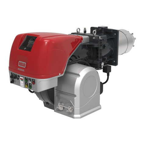
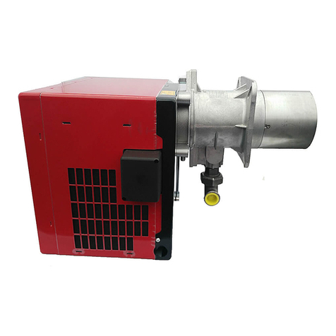
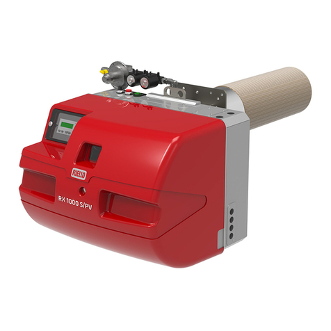
manuals.online logo
Brands
  1. Home
  2. •
  3. Brands
  4. •
  5. Riello
  6. •
  7. Indoor Fireplace
  8. •
  9. Riello LPG kit Quick start guide

Riello LPG kit Quick start guide

2902070 (11) - 11/2017
Istruzioni per installazione, uso e manutenzione
Installations-, Montage- und Betriebsanleitung
Instructions d’installation, montage et fonctionnement
Installation, use and maintenance instructions
Installatie-, gebruiks- en onderhoudsvoorschriften
Instrucciones de instalación, montaje y funcionamiento
Instruções de instalação, montagem e funcionamento
Oδηγίες εγκατάστασης, χρήσης και συντήρησης
Kit GPL
Flüssiggas-Umbausatz
Kit GPL
LPG kit
LPG kit
Kit GPL
Kit GPL
Κιτ LPG
CODICE - CODE
CÓDIGO - ΚΩΔΙΚΟΣ
MODELLO - MODEL - MODELE
MODELO - ΜΟΝΤΕΛΟ
TIPO - TYP
TYPE - ΤΥΠΟΣ
3001003 - 3002734
BS1 911T1
BS1D 915T1
BS1M 915M
3001004 - 3002735
BS2 912T1
BS2D 916T1
BS2D 921T1
3001005 - 3002736 BS3 913T1
BS3D 917T1
3001011 - 3002737
BS4 914T1
BS4D 918T1
BS4M 918M
RS5 - RS5F 920T1
RS5D 922T1
I
D
F
GB
NL
E
P
GR
3 2902070
Kit GPL - Flüssiggas-Umbausatz - LPG Kit - Κιτ LPG
(*) Kit per GPL con quantità di butano oltre il 30%. - (*) Flüssiggas-Kit mit Butan über 30%.
(*) LPG kit with butane amount over 30%. - (*) Kit GPL con cantidad de butano superior al 30%.
(*) Kit GPL avec une quantité de butane supérieure à 30%. - (*) Kit LPG met meer dan 30% butaan.
(*) Kit GPL com quantidade de butano mais de 30%. - (*) Κιτ ΥΓΡΑΕΡΙΟΥ με ποσότητα βουτανίου άνω του 30%.
CARATTERISTICHE TECNICHE - TECHNISCHE MERKMALE - CARACTERISTIQUES TECHNIQUES - TECHNICAL FEATU-
RES - TECHNISCHE KENMERKEN - CARACTERÍSTICAS TÉCNICAS - CARACTERÍSTICAS TÉCNICAS - ΤΕΧΝΙΚΑ
ΧΑΡΑΚΤΗΡΙΣΤΙΚΑ
Tab. A
GAS Famiglia 3 - GAS Familie 3 - GAZ Famille 3 - GAS Family 3 - GAS Familie 3 - Gas Familia 3 - GÁS Família 3 - ΑΕΡΙΟ 3ης
Οικογένειας
Tab. B
O Per tipo - Für Typ - Pour type - For type - Voor type - Para tipo - Para tipo - Για τύπο: 920T1 - 922T1.
TIPO - TYP
TYPE - ΤΥΠΟΣ
CODICE - CODE
CÓDIGO - ΚΩΔΙΚΟΣ
CODICE - CODE
CÓDIGO - ΚΩΔΙΚΟΣ (*)
911T1 - 915T1 - 915M 3001003 3002734
912T1 - 916T1 - 921T1 3001004 3002735
913T1 - 917T1 3001005 3002736
914T1 - 918T1 - 920T1 - 922T1 - 918M 3001011 3002737
Kit
Umbausatz
Modello - Model -
Modele Modelo -
Μοντελο
Tipo - Typ
Type - Tipo
Potenza termica - Wärmeleistung
Puissance thermique - Thermal output - Vermogen -
Potencia térmica - Potência térmica - Θερμική ισχύς
KW Mcal/h
3001003
GULLIVER BS1 911T1 16/19  52 13.8/16.3  44.7
GULLIVER BS1D 915T1 16/19  52 13.8/16.3  44.7
GULLIVER BS1M 915M 16/19 ÷ 52 13.8/16.3 ÷ 44,7
3001004
GULLIVER BS2 912T1 35/40  92 30./34.4  78.2
GULLIVER BS2D 916T1 35/40  92 30./34.4  78.2
GULLIVER BS2D 921T1 35/40  92 30./34.4  78.2
3001005 GULLIVER BS3 913T1 65/75  197 55.9/68.8  162.5
GULLIVER BS3D 917T1 65/75  197 55.9/68.8  162.5
3001011
GULLIVER BS4 914T1 110/140  249 94.6/120.4  215
GULLIVER BS4D 918T1 110/140  249 94.6/120.4  215
GULLIVER BS4M 918M 68/140 ÷ 250 58.5/120.4 ÷ 215
GULLIVER RS5 - RS5F 920T1 110/140  249 94.6/120.4  215
GULLIVER RS5D 922T1 110/140  249 94.6/120.4  215
Pci - Hu - Pouvoir calorifique - Net calorific value - Calorische waarde - Poder calorí-
fico Poder calorífico - Θερμαντική ισχύς 24  34 kWh/m3 - (21.000  29.000 kcal/m3)
Pressione rete - Anschlussdruck - Pression du circuit - Mains pressure
Druk gasnet - Presión red - Pressão de rede - Πίεση δικτύου
Min. 20 mbar
Max. 100 mbar
Paese - Land - Pays
Country - Land - País
País - Χώρα
IT GB DE AT DK FR NL BE IE
Categoria gas - Gaskategorie
Catégorie gaz - Gas category
Categorie gas - Categoría gas
Categoria gás
Κατηγορία αερίου
II2H3B/P II2H3P
II2ELL3B/P
II2E3B/P O
II2H3B/P II2H3B/P II2Er3P
I2L - I2E - I2
(43.46 ÷
45.3 MJ/
m3 (0°C))
I2E(R)B,I3P II2H3P
Pressione - Druck
Pression
Pressure - Druk
Presión - Pressão
Πίεση
G30 B 28 30/50 50 50 30 30/50 30 28/50 28
G31 P 30/37 50/67 50 50 30 37/50 30/50 37/67 37
2902070 4
Kit GPL - Flüssiggas-Umbausatz - LPG Kit - Κιτ LPG
Il kit consente ai bruciatori previsti per funzionamento a gas na-
turale, di bruciare GPL.
ELENCO DEI PEZZI CHE COMPONGONO IL KIT
Il campo di lavoro con GPL è uguale a quello dei bruciatori con
funzionamento a gas naturale.
(Far riferimento all’istruzione del bruciatore).
TRASFORMAZIONE
Sulla testa di combustione del bruciatori, vanno sostituiti il distri-
butore e la tazza per gas naturale con quelli per GPL forniti a cor-
redo del kit.
Procedere come segue:
Applicare la targhetta autoadesiva, come illustrato in fig. 1,
pag. 6.
Smontare il gruppo testa di combustione (fig. 2, pag. 6) dal
bruciatore seguendo le indicazioni riportate nell’istruzione
del bruciatore.
Smontare il distributore per gas naturale (1), completo di
tazza (3), dopo aver tolto le due viti di bloccaggio (2).
Smontare la tazza (3) dopo aver tolto le viti e rosette di bloc-
caggio (4).
Montare il nuovo distributore per GPL (1) e la tazza (3),
tenendo però allentate le viti (4) per consentire all’elettrodo
(5) di passare liberamente nel foro della tazza (3).
Bloccare infine le viti (4).
POSIZIONAMENTO SONDA ELETTRODO
(vedi fig. 4, pag. 7)
REGOLAZIONE TESTA DI COMBUSTIONE
È la stessa dei bruciatori per funzionamento a gas naturale. (Far
riferimento all’istruzione del bruciatore).
CORRELAZIONE TRA PRESSIONE DEL GAS E
POTENZIALITÀ (vedi fig. 3, pag. 6)
Pressione misurata al manicotto del bruciatore funzionante con
GPL Pci 23.000 kcal/m3 e con camera di combustione a 0 mbar.
Der Umbausatz ermöglicht es, mit einem für die Verwendung von
Erdgas vorgesehenen Brenner Flüssiggas zu verfeuern.
IM UMBAUSATZ ENTHALTENE TEILE
Das Arbeitsfeld mit Flüssiggas ist wie jenes der mit Erdgas betrie-
benen Brenner (siehe Brenneranleitung).
UMBAU
Am Flammkopf des Brenners sind der Erdgasverteiler und der
Erdgasbecher mit den im Umbausatz mitgelieferten auszutau-
schen.
Wie folgt vorgehen:
Das Selbstklebeschild, wie in Abb. 1, Seite 6 gezeigt, anbrin-
gen.
Den Flammkopfblock (Abb. 2, Seite 6) nach den Angaben in
der Brenneranleitung vom Brenner abmontieren.
Den Erdgasverteiler (1) komplett mit Becher (3) abmontie-
ren, nachdem die zwei Feststellschrauben (2) abgeschraubt
worden sind.
Den Becher (3) abmontieren, nachdem die Schrauben und
die Feststellscheiben (4) entfernt worden sind.
Den neuen Flüssiggasverteiler (1) und den Becher (3) ein-
bauen, dabei die Schrauben (4) gelockert halten, damit die
Elektrode (5) in das Loch des Bechers (3) geht.
Am Ende die Schrauben (4) fest anziehen.
STELLUNG VON FÜHLER UND ELEKTRODE
(siehe Abb. 4, Seite 7)
FLAMMKOPFEINSTELLUNG
Ist wie für die mit Erdgas betriebenen Brenner (siehe Brenneran-
leitung).
GASDRUCK - BRENNERLEISTUNG
(siehe Abb. 3, Seite 6)
Am Gasanschluss des mit Flüssiggas betriebenen Brenners ge-
messener Druck (Pci 23.000 kcal/m3), bei einem Brennkammer-
druck von 0 mbar.
Tutte le operazioni di installazione, manutenzione e
smontaggio devono assolutamente essere eseguite
con rete elettrica staccata.
L’installazione del bruciatore deve essere effettuata
da personale abilitato, secondo quanto riportato nel
presente manuale ed in conformità alle norme e
disposizioni di legge vigenti.
Quantità Descrizione
1
1
1
1
Distributore
Targhetta autoadesiva
Istruzione
Tazza
ITALIANO
PERICOLO
ATTENZIONE
Alle Arbeiten zur Installation, Wartung und
Demontage müssen unbedingt bei abgeschaltetem
Stromnetz ausgeführt werden.
Die Installation des Brenners muss durch
Fachpersonal gemäß den Angaben in diesem
Handbuch sowie in Übereinstimmung mit den gültigen
gesetzlichen Normen und Bestimmungen ausgeführt
werden.
Stückzahl Bauteil
1
1
1
1
Verteiler
Selbstklebeschild
Betriebsanleitung
Stauscheibe
DEUTSCH
GEFAHR
ACHTUNG
5 2902070
Kit GPL - Flüssiggas-Umbausatz - LPG Kit - Κιτ LPG
Ce kit permet aux brûleurs prévus pour le fonctionnement au gaz
naturel de brûler du GPL.
LEGENDE COMPOSANTS KIT
La plage de travail pour les brûleurs fonctionnant au GPL est la
même que celle des brûleurs fonctionnant au gaz naturel.
(Voir instructions du brûleur).
TRANSFORMATION
Remplacer le distributeur et le distributeur d’air pour le gaz natu-
rel par ceux pour le GPL fournis avec le kit sur la tête de combu-
stion des brûleurs.
Procedure de travail:
Coller la plaque adhésive comme montré à la fig. 1, page 6.
Démonter le groupe de la tête de combustion (fig. 2, page 6)
en suivant les indications reportées dans les instructions du
brûleur.
Démonter le distributeur pour le gaz naturel (1) ainsi que le
distributeur d’air (3) après avoir enlevé les deux vis de blo-
cage (2).
Démonter le distributeur d’air (3) après avoir enlevé les vis
et les rondelles de blocage (4).
Monter le distributeur pour G.P.L. neuf (1) et le distributeur
d’air (3) en ne serrant pas complètement les vis (4) pour que
l’électrode (5) puisse passer librement à travers l’ouverture
du distributeur d’air (3).
Serrer complètement les vis (4).
POSITIONNEMENT SONDE - ELECTRODE
(voir fig. 4, page 7)
REGLAGE TETE DE COMBUSTION
La tête de combustion se règle de la même façon que pour les
brûleurs fonctionnant au gaz naturel. (Voir instructions du brûl-
eur).
RAPPORT ENTRE LA PRESSION DU GAZ ET LA
PUISSANCE (voir fig. 3, page 6)
Pression mesurée au manchon du brûleur fonctionnant au gaz
GPL Pci 23.000 kcal/m3 et avec chambre de combustion à 0
mbar.
The LPG kit allows the above burners, suitable to run on natural
gas, to burn LPG.
LIST OF KIT’S COMPONENTS
The working field with LPG is the same as that of the burners run-
ning on natural gas.
(Refer to burner's instructions).
CONVERSION
On the combustion head of the burners, the natural gas distribu-
tor and air diffuser should be replaced with the ones for use with
LPG, supplied in the kit.
Proceed as follows:
Affix the adhesive label, as illustrated in fig. 1, page 6.
Remove the combustion head assembly (fig. 2, page 6) from
the burner, following the directions indicated in the technical
instructions of the burner.
Remove the natural gas distributor (1), complete with air dif-
fuser (3), once you have removed the two locking screws
(2).
Remove the screws and lock washers (4) then take off the
air diffuser (3).
Install the new LPG distributor (1) and the air diffuser (3), but
keep the screws (4) loose so that the electrode (5) can pass
clearly through the diffuser hole (3).
Lastly, tighten the screws (4).
PROBE - ELECTRODE POSITIONING
(see fig. 4, page 7)
COMBUSTION HEAD ADJUSTMENT
This is the same as for burners running on natural gas. (Refer to
burner's instructions).
CORRELATION BETWEEN GAS PRESSURE AND BURNER
OUTPUT (see fig. 3, page 6)
Pressure measured at the pipe coupling of the burner running on
LPG net calorific value 23.000 kcal/m3, with combustion chamber
at 0 mbar.
Toutes les opérations d'installation, entretien et
démontage doivent être effectuées avec le réseau
électrique débranché.
L'installation du brûleur doit être effectuée par du
personnel habilité, selon les indications reportées
dans ce manuel et conformément aux normes et
dispositions en vigueur.
Quantité Description
1
1
1
1
Distributeur
Plaque adhésive
Instructions
Diffuseur d’air
FRANÇAIS
DANGER
ATTENTION
All the installation, maintenance and disassembly
operations must be carried out with the electricity
supply disconnected.
The installation of the burner must be carried out by
qualified personnel, as indicated in this manual and
in compliance with the standards and regulations of
the laws in force.
Quantity Description
1
1
1
1
Distributor
Adhesive label
Technical instructions
Air diffuser
ENGLISH
DANGER
WARNING

Other manuals for LPG kit

1

Other Riello Indoor Fireplace manuals

Riello PRESS GW Quick start guide

Riello

Riello PRESS GW Quick start guide

Riello RLS 1000/M C13 Quick start guide

Riello

Riello RLS 1000/M C13 Quick start guide

Riello RS 190 Quick start guide

Riello

Riello RS 190 Quick start guide

Riello RS5F Quick start guide

Riello

Riello RS5F Quick start guide

Riello BS1D Quick start guide

Riello

Riello BS1D Quick start guide

Riello GAS 4 Quick start guide

Riello

Riello GAS 4 Quick start guide

Riello G20D Quick start guide

Riello

Riello G20D Quick start guide

Riello RS 160/M LN Quick start guide

Riello

Riello RS 160/M LN Quick start guide

Riello 40 Series Quick start guide

Riello

Riello 40 Series Quick start guide

Riello RS 810/EV O2 BLU Instruction Manual

Riello

Riello RS 810/EV O2 BLU Instruction Manual

Riello 40 D8 User manual

Riello

Riello 40 D8 User manual

Riello RX25 S/PV H Quick start guide

Riello

Riello RX25 S/PV H Quick start guide

Riello GS10D User manual

Riello

Riello GS10D User manual

Riello RS 70/M Quick start guide

Riello

Riello RS 70/M Quick start guide

Riello RS 1000/M C01 Quick start guide

Riello

Riello RS 1000/M C01 Quick start guide

Riello 976 T Quick start guide

Riello

Riello 976 T Quick start guide

Riello RS 250/M MZ Quick start guide

Riello

Riello RS 250/M MZ Quick start guide

Riello GAS 4 Quick start guide

Riello

Riello GAS 4 Quick start guide

Riello RS/M Series Quick start guide

Riello

Riello RS/M Series Quick start guide

Riello GAS 3/2 Manual

Riello

Riello GAS 3/2 Manual

Riello G900 Quick start guide

Riello

Riello G900 Quick start guide

Riello RS 1200/E BIOGAS/GPL C01 FS2 Quick start guide

Riello

Riello RS 1200/E BIOGAS/GPL C01 FS2 Quick start guide

Riello MB 405/2 Guide

Riello

Riello MB 405/2 Guide

Riello Gulliver RS5D Quick start guide

Riello

Riello Gulliver RS5D Quick start guide

Popular Indoor Fireplace manuals by other brands

Napoleon NEFL42CHD-1 manual

Napoleon

Napoleon NEFL42CHD-1 manual

Masport WOOD FIRE installation guide

Masport

Masport WOOD FIRE installation guide

JAYLINE SS280 Installation & operation instructions

JAYLINE

JAYLINE SS280 Installation & operation instructions

Heat-N-Glo SL-32S Installation

Heat-N-Glo

Heat-N-Glo SL-32S Installation

kozy heat Bellingham 52 quick start guide

kozy heat

kozy heat Bellingham 52 quick start guide

Paragon Fires ROOM SEALED INSET LIVE FUEL EFFECT GAS FIRE owner's manual

Paragon Fires

Paragon Fires ROOM SEALED INSET LIVE FUEL EFFECT GAS FIRE owner's manual

Monessen Hearth LCUF32CR-B Installation & owner's manual

Monessen Hearth

Monessen Hearth LCUF32CR-B Installation & owner's manual

PuraFlame Galena owner's manual

PuraFlame

PuraFlame Galena owner's manual

Dimplex Toluca Deluxe instruction manual

Dimplex

Dimplex Toluca Deluxe instruction manual

SEI TENNYSON FA8544AO Assembly instructions

SEI

SEI TENNYSON FA8544AO Assembly instructions

Dru G25 installation manual

Dru

Dru G25 installation manual

Capital fireplaces Designline DL700 Installation and user instructions

Capital fireplaces

Capital fireplaces Designline DL700 Installation and user instructions

IronStrike VINTAGE VINT-DVS-U Installation and operation

IronStrike

IronStrike VINTAGE VINT-DVS-U Installation and operation

ACR Heat HERITAGE N25 Installation and operating instruction manual

ACR Heat

ACR Heat HERITAGE N25 Installation and operating instruction manual

European Home HVF-42 Installation, operation and owner's manual

European Home

European Home HVF-42 Installation, operation and owner's manual

Quadra-Fire MTVERNINSAE-MBK Owner's manual operation & care

Quadra-Fire

Quadra-Fire MTVERNINSAE-MBK Owner's manual operation & care

Harman Home Heating Accentra Insert Installation & operating manual

Harman Home Heating

Harman Home Heating Accentra Insert Installation & operating manual

Trimline Fires Zircon 1024 installation instructions

Trimline Fires

Trimline Fires Zircon 1024 installation instructions

manuals.online logo
manuals.online logoBrands
  • About & Mission
  • Contact us
  • Privacy Policy
  • Terms and Conditions

Copyright 2025 Manuals.Online. All Rights Reserved.