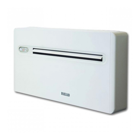
Riello AARIA ONE INVERTER 25 Operating instructions

AARIA ONE INVERTER
02/2017
cod.Doc-0083695rev.0
EN INSTALLATION AND TECHNICAL SERVICE INSTRUCTIONS

2
AARIA ONE INVERTER
COMPLIANCE
RAARIA ONE INVERTER heat pumps are compliant with the following European Directives:
—Low Voltage Directive 2014/35/EU
—Electromagnetic Compatibility Directive 2014/30/EU
—RoHS Directive 2011/65/EU
—Directive 2010/30/EU Indication of the energy consumption on the labels of products related to energy consumption
—WEEE Directive 2012/19/EU
—ErP Directive 2009/125/EC and Regulation 2012/206/EC
Dear Technician,
We would like to congratulate you on having recommended a Runit: a modern product that is capable of ensuring maximum
comfort at length, with a high degree of reliability, efficiency, quality and safety.
While your technical skills and knowledge will certainly be more than sufficient, this booklet contains all the information that we
have deemed necessary for the device’s correct and easy installation.
Thank you again, and keep up the good work.
RIELLO
RANGE
Model Code
AARIA ONE INVERTER 25 20131342
ACCESSORIES
For the complete list of accessories and the information relating to their usage combinations, please refer to the catalogue.

AARIA ONE INVERTER
3
TABLE OF CONTENTS
1 GENERAL INFORMATION . . . . . . . . . . . . . . . . . .
p. 4
1.1 General Notices . . . . . . . . . . . . . . . . . . . . . . . . . . . . .
p. 4
1.2 Safety precautions . . . . . . . . . . . . . . . . . . . . . . . . . . .
p. 4
1.3 Unit description . . . . . . . . . . . . . . . . . . . . . . . . . . . . .
p. 5
1.4 Safety and adjustment devices. . . . . . . . . . . . . . . . . .
p. 5
1.5 Identification . . . . . . . . . . . . . . . . . . . . . . . . . . . . . . .
p. 5
1.6 Layout . . . . . . . . . . . . . . . . . . . . . . . . . . . . . . . . . . . .
p. 6
1.7 Technical specifications . . . . . . . . . . . . . . . . . . . . . . .
p. 7
1.8 Operating limits . . . . . . . . . . . . . . . . . . . . . . . . . . . . .
p. 9
1.9 Cooling circuit . . . . . . . . . . . . . . . . . . . . . . . . . . . . . .
p. 9
2 INSTALLATION . . . . . . . . . . . . . . . . . . . . . . . . . .
p. 10
2.1 Receiving the product . . . . . . . . . . . . . . . . . . . . . . .
p. 10
2.2 Labels positioning . . . . . . . . . . . . . . . . . . . . . . . . . .
p. 10
2.3 Dimensions and weight . . . . . . . . . . . . . . . . . . . . . .
p. 10
2.4 Storage . . . . . . . . . . . . . . . . . . . . . . . . . . . . . . . . . . .
p. 11
2.5 Handling and removal of the packing . . . . . . . . . . . .
p. 11
2.6 Place of installation . . . . . . . . . . . . . . . . . . . . . . . . . .
p. 12
2.7 Recommended distances. . . . . . . . . . . . . . . . . . . . . .
p. 12
2.8 Installation on old systems or systems in need of
upgrading . . . . . . . . . . . . . . . . . . . . . . . . . . . . . . . . .
p. 12
2.9 Positioning. . . . . . . . . . . . . . . . . . . . . . . . . . . . . . . . .
p. 13
2.10 Condensate discharge connection . . . . . . . . . . . . . . .
p. 15
2.11 Wiring diagram . . . . . . . . . . . . . . . . . . . . . . . . . . . .
p. 16
2.12 Electrical connection . . . . . . . . . . . . . . . . . . . . . . . . .
p. 17
2.13 Mounting the low-wall unit. . . . . . . . . . . . . . . . . . .
p. 18
Mounting the high-wall unit . . . . . . . . . . . . . . . . . .
p. 19
2.14 Controls . . . . . . . . . . . . . . . . . . . . . . . . . . . . . . . . . .
p. 20
3 COMMISSIONING AND MAINTENANCE . . . .
p. 22
3.1 Preparation for first commissioning . . . . . . . . . . . . .
p. 22
3.2 Putting into service . . . . . . . . . . . . . . . . . . . . . . . . .
p. 24
3.3 Temporary shutdown. . . . . . . . . . . . . . . . . . . . . . . .
p. 24
3.4 Stop for an extended period of time . . . . . . . . . . . .
p. 24
3.5 Ordinary maintenance . . . . . . . . . . . . . . . . . . . . . . .
p. 24
3.6 Extraordinary maintenance . . . . . . . . . . . . . . . . . . .
p. 25
3.7 Alarms . . . . . . . . . . . . . . . . . . . . . . . . . . . . . . . . . . .
p. 25
4 DISPOSAL. . . . . . . . . . . . . . . . . . . . . . . . . . . . . . .
p. 27
The following symbols are used in this publication:
9
WARNING = actions requiring special care and appropri-
ate training.
0 DO NOT = actions that MUST ON NO ACCOUNT be carried
out.
This booklet cod. Doc-0083695 rev. 0 (02/2017) consists of 28 pag-
es.

GENERAL INFORMATION
4
1
GENERAL INFORMATION
1.1
General Notices
9
When you get the product, check immediately that the con-
tents are all present and undamaged. Contact the dealer
Rif you notice any problems.
9
The product’ s installation must be carried out by an au-
thorised company that will issue a declaration of the instal-
lation’s conformity to the product’s owner once the work
has been completed, indicating that the work has been car-
ried out in accordance with the standards of good practice,
current National and Local regulations, and the indications
provided by Rin the instruction booklet accompanying
the device.
9
The product must be used for its intended purpose, as stat-
ed by Rfor which it has been expressly manufactured.
Rshall bear no responsibility, whether of a contractual
or non-contractual nature, for any damage caused to peo-
ple, animals, or property due to incorrect installation, ad-
justments, or maintenance, or improper use.
9
Suitable clothing, instrumentation, and accident-preven-
tion devices must be utilized during the installation and/
or maintenance operations. Rshall bear no responsi-
bility for any failure to comply with current safety and acci-
dent-prevention regulations.
9
During installation and/or service operations, keep the area
around the unit tidy and clean.
9
Comply with the legislation in force on the country of de-
ployment with regard to the use and disposal of packaging,
of cleaning and maintenance products and for the man-
agement of the unit’s decommissioning.
9
Any repair and maintenance interventions must be carried
out by RTechnical Support Service, in accordance with
the provisions contained in this publication. Do not modify
or tamper with the unit as dangerous situations may arise
and the unit manufacturer will not be liable for any damage
caused.
9
In the event of any functional anomalies or fluid leaks, set
the system’s main switch to its “off” position. Promptly con-
tact your local RTechnical Support Service, and do not
perform any interventions upon the device on your own.
9
The units contain refrigerant gas: operate carefully so as to
avoid damaging the gas circuit and the fin bank.
9
Any gas leaks indoors can generate toxic gases if they come
into contact with naked flames or high temperature bodies,
in case of leaks, please air the rooms thoroughly.
9
According to EU Regulation no. 517/2014 regarding certain
fluorinated greenhouse gases, the total amount of refrig-
erant contained within the installed system must be indi-
cated. This information can be found on the unit technical
data plate.
9
This unit contains fluorinated greenhouse gases covered
by the Kyoto protocol. Maintenance and disposal activities
must be carried out exclusively by skilled personnel.
9
This booklet is an integral part of the device, and must
therefore be carefully preserved, and must ALWAYS accom-
pany it, even in the event that it is sold to another Owner
or User, or is transferred to another system. If it is damaged
or lost, another copy can be requested to RTechnical
Support Service in your Area.
1.2
Safety precautions
It should be noted that the use of products that utilize elec-
tric energy requires certain essential safety regulations to be re-
spected, including the following:
0 Do not allow children or unassisted disabled people to use
the unit.
0 It is forbidden to touch the device while barefoot or with wet
body parts.
0 Do not spray or throw water directly on the unit.
0 It is forbidden to place weights on the device.
0 It is strictly forbidden to touch the coil fins, the moving parts,
to place any body parts between them, or to insert pointy
objects into the grilles.
0 It is forbidden to perform any technical interventions or
cleaning operations before having disconnected the de-
vice from its electrical power supply, by setting the system’s
main switch to its “OFF” position.
0 It is forbidden to modify the safety or adjustment devices
without the manufacturer’s authorisation.
0 Do not pull, detach or twist the electrical wires coming out
of the unit, even when the unit is disconnected from the
power grid.
0 The packing material must not be disposed of in the sur-
rounding environment and must be kept out of children
reach, as it can be dangerous. It must be disposed of ac-
cording to the regulations in force.
GENERAL INFORMATION
5
1.3
Unit description
RAARIA ONE INVERTER is a dual duct climate control system
suitable for wall installation on any perimeter wall. The aesthetic
impact is reduced significantly both on the outside where only
two 162 mm holes will be visible, and inside the house thanks
to a depth of only 170 mm, smaller than conventional indoor
climate control units.
The rotary-type compressor is regulated by the DC-inverter con-
trol with continuous modulation, ensuring high energy stand-
ards. The DC fan motor improves performance and reduces the
noise level. The expansion valve electronically optimises the flow
of refrigerant in the circuit.
Control, adjustment and programming are carried out using the
on-board control or the infrared remote control, whose opera-
tion and use are described in the user manual.
1.4
Safety and adjustment devices
The device safety and setting are achieved thanks to:
• temperature sensor of the upper heat exchanger, transmits
the detected value to the main electronic board which acti-
vates:
—heating mode if the detected temperature is greater than
52°C, turning off the lower fan which then restarts when
the temperature is lower than or equal to 47°C
—heating mode if the detected temperature is greater than
62°C for 10 seconds, turning off the compressor which then
restarts when the temperature is lower than or equal to
47°C
—cooling and dehumidification if the detected temperature
is lower than 0°C for 20 seconds, turning off the compres-
sor and the lower fan that restart when the temperature is
greater than 7°C
• temperature probe of the lower heat exchanger, transmits the
detected value to the main electronic board which activates:
—cooling mode if the detected temperature is greater than
58°C, increasing the speed of the lower fan until the tem-
perature is lower than 55°C
—cooling mode if the detected temperature is greater than
62°C, turning off the unit which then restarts after 60 sec-
onds when the temperature is lower than 62°C
—cooling and dehumidification mode if the detected tem-
perature is lower than 25°C, forcing the lower fan to oper-
ate at minimum speed
• temperature sensor of compressor outlet, transmits the value
to the electronic board which acts when the temperature is
greater than 110°C, turning off the unit
• external air temperature sensor, which transmits the detect-
ed value to the electronic board to act on the unit’s operation
and adapt it to variations in external conditions
• room air temperature sensor, which transmits the detected
value to the electronic board to act on the unit’s operation
and to adjust the room temperature
• safety float in the condensation pan that turns off the unit if
the level of condensation is too high
9
Safety device replacement must be carried out by R
Technical Support Service, using only original components.
Please refer to the spare parts catalogue.
0 IT IS FORBIDDEN to operate the device with faulty safety sys-
tems.
1.5
Identification
The unit can be identified through the technical data plate:
12345678
Technical data plate
Contains the device’s technical and performance data.
9
The tampering, removal, or absence of the identification
plates will not allow the product to be properly identified by
its serial number.

GENERAL INFORMATION
6
1.6
Layout
1 Control panel
2 Air outlet deflector
3 Front panel
4 Intake grid
5 Decorative side panel
6 External air intake
7 External air expulsion
8 Condensation discharge
9 Anti-lifting bracket
10 Remote control
11 Terminal blocks
12 Air filter
13 Room air probe
14 Upper exchanger
15 Lower Fan
16 Condensation pump
17 Lower exchanger
18 Maximum level float
19 Level float
20 Condensation drain valve
21 Four-way valve
22 Compressor
23 External air probe
4
12
23
22
3
6
7
8
9
1
13
5
2
10
11
14
15
16
17
19
18
20
21

GENERAL INFORMATION
7
1.7
Technical specifications
Performance
Model 25
Cooling performance [A35 / A27] (1)
Capacity at maximum air flow 2,04 kW
Absorbed power at maximum air flow 0,63 kW
EER 3,21 kW/kW
Capacity at maximum power 2,60 kW
Power consumption at maximum power 0,81 kW
Average air flow rate capacity 1,75 kW
Power consumption with average air flow rate 0,54 kW
Capacity at minimum air flow 1,53 kW
Absorbed power at minimum air flow 0,47 kW
Heating performance [A7 / A20] (2)
Capacity at maximum air flow 2,10 kW
Absorbed power at maximum air flow 0,64 kW
COP 3,30 kW/kW
Capacity at maximum power 2,64 kW
Power consumption at maximum power 0,80 kW
Average air flow rate capacity 1,62 kW
Power consumption with average air flow rate 0,49 kW
Capacity at minimum air flow 1,43 kW
Absorbed power at minimum air flow 0,43 kW
Dehumidification performance
Dehumidification capacity 1,00 l/h
Upper Fan
Fan Tangential Type
Speed 3n.
Maximum air flow 380 m³/h
Medium air flow 310 m³/h
Minimum air flow 260 m³/h
Maximum speed 1500 rpm
Medium speed 1250 rpm
Minimum speed 900 rpm
Lower Fan
Fan Centrifugal Type
Speed 3n.
Maximum air flow 460 m³/h
Medium air flow 380 m³/h
Minimum air flow 330 m³/h
Maximum speed 2100 rpm
Medium speed 1700 rpm
Minimum speed 1350 rpm
Compressor
Compressor Rotary Type
Adjustment Inverter Type
Refrigerant R410A Type
Refrigerant charge 0,56 kg
Maximum allowable pressure PS 3,80 MPa
Sound level internal side
Maximum sound pressure (3) 40 dB(A)
Medium sound pressure (3) 34 dB(A)
Minimum sound pressure (3) 31 dB(A)
Maximum sound power 57 dB(A)
Medium sound power 51 dB(A)
Minimum sound power 48 dB(A)
Sound level external side
Maximum sound pressure (3) 52 dB(A)
Medium sound pressure (3) 45 dB(A)
Minimum sound pressure (3) 40 dB(A)
Maximum sound power 69 dB(A)
Medium sound power 62 dB(A)
Minimum sound power 57 dB(A)
(1) Outdoor air: 35 °C D.B., Indoor air: 27 °C D.B. / 19 ° W.B.
(2) Outdoor air: 7 °C D.B. / 6 °C W.B., Indoor air: 20 °C D.B.
(3) Misurato a 2 metri fronte unità

GENERAL INFORMATION
8
Energy data
Model 25
Ecodesign data and Energy Labelling (1)
Standby mode (PSB) 0,5 W
Thermostat-off mode (PTO) 11,0 W
GWP 2088
Sound power level 57 dB(A)
Cooling
Nominal capacity 2,60 kW
Nominal power input 0,81 kW
EER 3,21 kW/kW
Energy class A+
Hourly energy consumption 0,8 kWh/h
Heating
Nominal capacity 2,64 kW
Nominal power input 0,80 kW
COP 3,30 kW/kW
Energy class A
Hourly energy consumption 0,8 kWh/h
(1) According to regulations 206/2012 and 626/2011
Electrical characteristics
Model 25
Electrical characteristics
Power supply 230/1/50 V/Ph/Hz
Protection factor X0 IP
Cooling performance [A35 / A27] (1)
Power consumption at maximum air flow 2,90 A
Current consumption at maximum power 4,40 A
Power consumption at average air flow 2,46 A
Power consumption at minimum air flow 2,14 A
Maximum frequency 52 Hz
Frequency at maximum power 68 Hz
Average frequency 44 Hz
Minimum frequency 37 Hz
Heating performance [A7 / A20] (2)
Power consumption at maximum air flow 2,89 A
Current consumption at maximum power 4,40 A
Power consumption at average air flow 2,25 A
Power consumption at minimum air flow 1,98 A
Maximum frequency 68 Hz
Frequency at maximum power 75 Hz
Average frequency 52 Hz
Minimum frequency 45 Hz
(1) Outdoor air: 35 °C D.B., Indoor air: 27 °C D.B. / 19 ° W.B.
(2) Outdoor air: 7 °C D.B. / 6 °C W.B., Indoor air: 20 °C D.B.

GENERAL INFORMATION
9
1.8
Operating limits
COOLING
A Outdoor air temperature (B.S.)
B Indoor air temperature (B.S.)
A (°C)
-15
-5
5
15
25
35
43
55
18 25 30 35 B (°C)
HEATING
A Outdoor air temperature (B.S.)
B Indoor air temperature (B.S.)
A (°C)
-25
-15
-10
0
10
20
24
30
40
105 15 20 2527 B (°C)
1.9
Cooling circuit
The cooling circuit is of the heat pump type with a refrigerant gas
reversal cycle. The source fluid utilised is the outdoor air, while
the utility-side fluid is the air inside the rooms.
During the wintertime, the heat pump extracts the thermal en-
ergy from the outdoor air and delivers it to the room air, thereby
heating it. During the summertime the cycle is reversed, and the
thermal energy is extracted from the room air, which is cooled,
and is delivered to the outdoor air.
1 Compressor
2 Discharge temperature sensor
3 Cycle reversal valve
4 Electric fan
5 Heat exchanger
6 External air probe
7 Defrost temperature sensor
8 Electronic expansion valve
9 Heat exchanger
10 Heat exchanger sensor
11 Electric fan
12 Room air probe
13 Intake separator
1
2
3
6
7
12
13
10
11
9
8
45

INSTALLATION
10
2
INSTALLATION
2.1
Receiving the product
RAARIA ONE INVERTER is supplied in a single package, pro-
tected by a cardboard packaging, polystyrene elements and a
polyethylene film.
The following items can be found inside the packaging:
Document envelope:
—Instruction’s book for the installer and for the Technical
Service in Italian
—Instruction’s book for the installer and for the Technical
Service in English
—instruction booklet for the installer and the Technical
Support Service in French
—instruction booklet for the installer and the Technical
Support Service in Spanish
—user instruction booklet in Italian
—user instruction booklet in English
—user instruction booklet in French
—user instruction booklet in Spanish
—Warranty/Spare parts labels.
—energy label
—warranty terms for Italy
It is also supplied as kit:
—remote control
—CR2025 3V battery
—no. 2 external dampers for air inlet and outlet including
springs and chains
—no. 2 plastic sheet for ducts
—no. 2 counterflanges for inner wall
—no. 6 screws and anchor bolts
—paper template
—0.6 m of condensation drain tube
—lower covering panel
—no. 2 screws for lower cover panel fastening
9
The Instruction book comes with the equipment and it
should be taken, read and kept carefully.
9
The document envelope must be kept in a safe place. Any
duplicate must be requested from Riello S.p.A. which re-
serves to charge the cost.
2.2
Labels positioning
A Package label
A
A
2.3
Dimensions and weight
L
P
H
Model 25
Packaging dimensions
H660 mm
L1110 mm
P260 mm
Weight 48,5 kg

INSTALLATION
11
L
P
H
Model 25
Product dimensions
H555 mm
L1030 mm
P170 mm
Weight 46,5 kg
2.4
Storage
9
The product must be stored of according to the regulations
in force.
2.5
Handling and removal of the packing
9
Before unpacking, personal protective clothing should be
worn and used transport means and tools suitable for the
size and weight of the unit.
Product handling can also be done manually by grasping the
handles provided on the packaging.
1 Handles
A
A
Follow the below instructions for packing removal and product
handling:
—transport the equipment in the installation place
—open the cardboard packaging
1 Lower closing panel
1
—remove the lower closing panel
1 Polystyrene elements
2 Metal support
3 Paper template and plastic sheets for ducts
12
3
—remove the metal support
—remove the polystyrene elements
—remove the paper template
—remove the plastic sheets for ducts
—remove the document envelope
—remove the envelope with the material supplied with the
unit
—remove the polyethylene bag
—take out the device by lifting it up
9
In manual operation it is compulsory to respect always the
maximum weight per person provided for by the national
laws and standards.
9
Handle with care
9
The equipment must always be handled vertically
9
The device is heavier on the right side (compressor side).
9
The packing material must not be disposed of in the sur-
rounding environment and must be kept out of children
reach, as it can be dangerous. It must be disposed of ac-
cording to the regulations in force.

INSTALLATION
12
2.6
Place of installation
The location of the RAARIA ONE INVERTER devices must be
determined by the system’s designer or by another competent
person, and must take into account technical requirements, as
well as any current local regulations.
RAARIA ONE INVERTER is designed for indoor wall installa-
tion:
A Side of the wall towards the interior
B Side of the wall towards the exterior
1 Perimeter wall
2 Device
3 Return and expulsion grilles
4 Outside air ducts
A
1
2
3
4
B
—install the device adjacent to a perimeter wall communi-
cating with the outside
—install the device in the room needing climate control
—its position must allow for the circulation of treated air in
the whole room
—consider an area where there are no obstacles to the reg-
ular air delivery and intake
Check that:
—the support wall is able to support the device weight
—the wall section does not feature building supporting ele-
ments, pipes or power lines
—the supplied wall plugs are suitable for the chosen support
wall
Avoid:
—installing the device in hallways or passageways
—any obstacles or barriers that will cause the expelled air to
recirculate
—locations with aggressive or explosive atmospheres or with
inflammable fluids
—direct exposure to sunlight and proximity to heat sources
—humid locations or positions where the unit could come
into contact with water
—locations with oil vapours
—locations with high frequency contamination
9
Avoid placing the unit less than 1 metre away from radio and
video systems.
2.7
Recommended distances
The distances for the device installation and maintenance are
shown in the figure. The indicated spaces are necessary in order
to prevent the airflow from being blocked, as well as to allow
normal cleaning and maintenance operations to be carried out.
The device can be installed in high-wall or low-wall mode.
In case of high-wall installation, it is necessary to install the
bottom cover panel supplied with the unit. For installation refer
to Chapter “Mounting the high-wall unit”
p. 19
.
A High-wall installation
B Low-wall installation
120
60
A
60
B
50
2000
2.8
Installation on old systems or systems in need
of upgrading
When RAARIA ONE INVERTER is installed on old systems or
systems in need of upgrading, it is recommended to ensure that:
—the electrical system is compliant with the applicable reg-
ulations and has been installed by qualified professionals

INSTALLATION
13
9
In the event of a replacement, the system must be inspected
by the designer or by another competent person, and must
be compliant with the technical requirements, as well as
the current legislations and regulations.
9
The manufacturer shall bear no responsibility for any dam-
ages caused by incorrect system installation.
2.9
Positioning
RAARIA ONE INVERTER units are supplied with a paper tem-
plate for marking the necessary installation holes.
A Area for the passage of electrical connections
B Holes for fastening the metallic support (for Ø 8 blocks)
C Holes for external air ducts
D Condensation drain Ø 16
E Hole for anti-lifting fastening (for Ø 8 block)
1008
A
B
C
DE
64 80 80 80
196,8 293
13973
28,5 404
80 80 80 80 80 80 80 80
56,9
555
17,5
13,3
106,4104,4190
Wall drilling for ducts:
A Side of the wall towards the interior
B Side of the wall towards the exterior
1 Perimeter wall
2 Device
3 Return and expulsion grilles
4 Outside air ducts
A
1
2
3
4
B
—position the paper template
9
Respect the distances shown in Chapter “Recommended
distances”
p. 12
.
—mark the positions of the holes for the ducts
—use a drill
—drill a pilot hole
—use a core drill
—drill the through hole into the wall
—keep a downward inclination toward the external side
9
The maximum length of the holes is 1 meter.
0 Curves are prohibited.
9
To prevent the creation of large quantities of dust and debris
in the room it is recommended to couple the core drill to a
vacuum system.
9
Proceed with caution in the vicinity of the outer wall in order
to avoid the breakage of plaster around the hole.
9
Take precautions so that the drilled material does not fall on
persons and objects below.
Positioning the ducts:
A Plastic sheet for ducts
A
—measure the depth of the holes drilled in the wall
—subtract 5 mm from the measurement
—cut the plastic sheets supplied to size
—roll the plastic sheet
—insert the rolled sheet into the hole
—position so that the edges of the sheet are 2 mm inside
both ends of the hole
Positioning outside air dampers:
The outside air dampers are different: it is necessary to distin-
guish the one for air intake from the one for expulsion.
The dampers are identified with the labels:
IN: air intake damper
OUT: air expulsion damper
9
Use only the dampers supplied with the unit.

INSTALLATION
14
1 Paper template
2 External air intake damper
3 External air expulsion damper
IN OUT
1
23
IN OUT
A Chain
B Counterflange
C Spring
D External air damper
A
B
C
D
—fold the damper
—insert it in the duct until it comes out on the other side of
the wall
—hold the chains with the other hand so that the damper
does not fall
—open the damper outside of the hole
—rotate the damper so that the flaps are in vertical position
—insert the counterflange in the hole toward the interior of
the room
—rotate it so that the hooks are in vertical position
—pull the chains so that the springs are in tension
—hook the chains to the counterflange
—cut off the excess of chain
9
When painting the dampers, use water-based paints suit-
able for plastic surfaces to avoid problems with the move-
ment of the flaps.
9
Do not use thick, sticky paints like enamels.
Fixing the metallic support to the wall:
The devices are provided with metallic support for mounting on
the wall.
1 Spirit level
2 Metal support
3 Fixing screw
4 Support wall
5 Wall plug
1
4
3
2
5
2
—use the paper template
—mark the position of the mounting holes
—use a drill
—drill holes in the marked positions
—fix the metallic support with the screws and the wall plugs
9
Place the metallic support on a level surface that is capable
of supporting its weight
9
Check that the installation is horizontal using a water level.
Assembly:
1 Interlocking points
2 Metal support
1
2
21
—fasten the unit to the upper part of the metallic support
—verify the correct hooking to the interlocking points
To ease the connections:
—use a spacer to keep the bottom of the unit spaced from
the wall

INSTALLATION
15
2.10
Condensate discharge connection
RAARIA ONE INVERTERcomes complete with a pan for col-
lecting the condensation that is produced during operation and
that must be conveyed to a suitable location for draining. The
size and positioning of the drainage tube are shown below.
1 Condensation drain connection (black plug)
2 Condensation drain stub
3 Retaining tie
4 Safety drain (white plug)
5 Insulating material
1
23
4
5
Model 25
Connections
Drainage pipe inner
diameter 10 mm
The device is factory supplied with a stub pipe connected to the
condensation drain connection. If it is not enough
—remove the stub pipe from the drain connection
—connect the drainage tube measuring 0.6 meters supplied
with the unit or a longer one
—direct it towards a suitable location for drainage
—keep a minimum slope of 3% towards the drain location
—insulate the joints
9
Ensure that all joints are properly sealed so as to prevent
water leaks.
9
The drainage pipe must be insulated for sections running
inside houses in order to prevent condensate formation on
its surface.
9
If needed it is possible to empty the condensation collection
pan through a safety drain provided on the base of the de-
vice. See Chapter “Extraordinary maintenance”
p. 25
.
If using a jug for collecting the condensation:
9
Avoid the hermetic closure of the container.
9
Prevent the end of the drainage tube from falling below the
water level.
If draining into the sewage system:
300 mm
3%
9
The discharge system must feature a suitable syphon in or-
der to prevent air from entering the vacuum system. The sy-
phon also prevents odours and insects from entering the
system.
9
The syphon must feature a plug in its lower part or must
otherwise allow for a quick disassembly for cleaning pur-
poses.
If using an open drain:
9
If the condensation is not collected, it will be deposited on
the support surface. The water could freeze if the outdoor
temperatures are below zero, thus creating a hazard. In this
case, appropriate barriers should be installed in order to
prevent people from approaching the area.

INSTALLATION
16
2.11
Wiring diagram
• Cable colour
BL Blue
YG Yellow/green
BR Brown
• PB Power board
N Neutral
G Earth
L Phase
• DB Driver board
I Inductance
C Compressor
U Phase 1
V Phase 2
W Phase 3
MC Compressor outlet probe (NTC 58 kΩat 25°C)
• MB Main board
OM Lower fan motor
IM Upper fan motor
PC Control panel
RT Room temperature probe (NTC 5.28 kΩat 25°C)
IPT Upper exchanger temperature probe (NTC 5.28 kΩ
at 25°C)
OT Outdoor temperature probe (NTC 5.28 kΩat 25°C)
OPT Lower exchanger temperature probe (NTC 5.28 kΩ
at 25°C)
GA Maximum level float (N.C. contact)
GL Level float (N.A. contact)
CP Presence contact (terminals C and P factory
bridged)
F Air outlet deflector
EEV Electronic expansion valve
4V 4-way valve
DV Condensation drain valve (power supply 230 V AC,
5A)
DP Battery condensation pump (power supply 230 V
AC, 5A)
N
BR
U
I
V
WXP209
BL YG
PB
DB
OM
IM
CN7
MB
PC
CN6
CN9
CN11
CN4
CN3
CN2
DP
DV
4V
CN18 IPT
RT
OPT
OT
CN17
CN15
CN14
CN10
CN13
GR
GL
CP
EEV
MC
C
F
GA
G
L

INSTALLATION
17
2.12
Electrical connection
AARIA ONE INVERTER leaves the factory fully wired and equipped
with a cable with Y-type plug for connection to the power sup-
ply. To power the unit simply insert the plug into a suitable sock-
et protected by a circuit breaker.
1 Main switch
2 Y-type socket
3 Plug supplied with the device
1
2
3
If necessary, it is possible to remove the factory cable with plug
and connect the power supply directly to the terminal block.
9
This operation must be done only by RTechnical Service
or qualified personnel.
ON
OFF
—set the system main switch to “OFF”
9
Wait 10 minutes before touching the device electric compo-
nents.
• To access the terminal board:
—lift the decorative side panels
—remove them by pulling horizontally
1 Plastic terminal board cover
2 Fixing screws
3 Front panel
4 Decorative side panel
5 Intake grid
5
14
3
2
To remove the intake grille:
—push it downwards
—slide it forward
—remove it by lifting
After having removed the intake grille:
—unscrew the fastening screws
—remove the front panel
—unscrew the fastening screws
—remove the plastic terminal box
—open the cable guide
—remove the factory wired cable

INSTALLATION
18
L Phase
N Neutral
IG System main switch
CP Presence contact
GR Grey
BR Brown
YG Yellow / green
BL Blue
GR GR
CP
LN
IG
GR
BL
YG
BR
—connect the new power cord
For the sizing of the electrical power cables, use the following
table:
Model 25
Electrical characteristics
Power supply 230/1/50 V/Ph/Hz
Power cable Double insulation Type
Power cable 3 x 1,5 n. x mm²
9
The cable sections specified in the table are minimum re-
quirements. The correct size must be calculated taking in-
to account the actual length, the type of routing and other
conditions set by the existing regulations.
—fasten the wires with the wire retainer
—complete the electric connections and refit all components
by performing the described operations in reverse order
Check that:
—the characteristics of the power network are suitable for
the device usage values
—the power supply voltage corresponds to the nominal val-
ue +/- 10%
—all of the power network disconnect devices must be
equipped with contact openings (3 mm) in order to allow
for complete disconnection, in accordance with the con-
ditions required
Mandatory items:
—have an omnipolar magneto-thermal circuit breaker and
a padlockable disconnecting switch compliant with the
IEC-EN Standards (contact opening of at least 3 mm), with
adequate breaking power and differential protection, in-
stalled near the equipment
—connect the device to a properly functioning earthing sys-
tem
—for any electrical intervention, always refer to the wiring
diagrams contained within this booklet
—take anti-static precautions in case of weather conditions
where humidity is less than 40%
9
Electric connections shall be made in compliance with na-
tional regulations.
9
Avoid placing the connection cables less than 1 metre away
from radio and video systems.
0 It is forbidden to earth the device together with pipes,
lightning conductors or the earthing system of a telephone
line. Using an improper earthing system can cause electric
shocks.
0 It is forbidden to connect other devices in parallel to the
unit.
Presence contact
Through this contact it is possible to connect an external de-
vice that inhibits operation of the unit such as: window open-
ing contact, remote on/off, infrared presence sensor, activation
badge etc. In case of power failure, the unit will restart with the
same settings if during the first 7 seconds after power supply is
restored no action is performed.
CP Presence contact
GR Grey
BR Brown
YG Yellow / green
BL Blue
GR GR
CP
GR
BL
YG
BR
To connect the contact:
—remove the jumper on the contact
—connect to a dry contact
• Logic:
—contact open: OFF, the control panel displays the symbol CP
—contact closed: ON
9
Use a double insulated cable.
9
It is prohibited to connect in series the CP contact of multiple
devices on the same dry contact.
2.13
Mounting the low-wall unit
After performing the connections:

INSTALLATION
19
1 Anti-lifting bracket
1
—remove the spacer
—lean the unit against the wall
—verify the absence of cracks between the rear of the unit
and the external air ducts
—fasten the anti-lifting bracket to the support wall
Mounting the high-wall unit
The device is supplied with a lower closure panel to be installed
in the case of high-wall installation.
To install:
—lift the decorative side panels
—remove them by pulling horizontally
1 Plastic terminal board cover
2 Fixing screws
3 Front panel
4 Decorative side panel
5 Intake grid
5
14
3
2
To remove the intake grille:
—push it downwards
—slide it forward
—remove it by lifting
After having removed the intake grille:
—unscrew the fastening screws
—remove the front panel
1 Fixing screw
2 Lower closing panel
2
1
1
—hook the bottom panel without fastening it with screws

INSTALLATION
20
1 Anti-lifting bracket
1
—lean the unit against the wall
—verify the absence of cracks between the rear of the unit
and the external air ducts
—fasten the anti-lifting bracket to the support wall
—close the lower panel
—secure with screws
—refit all components by performing the described opera-
tions in reverse order
2.14
Controls
Control, adjustment and programming are carried out using the
on-board control panel or the infrared remote control.
Based on the temperatures detected by the probes present in
the unit, the electronics modulates the operation of the device.
Control panel on board the unit
The control panel on board the unit is equipped with a touch
screen. Pressing the symbols activates their associated func-
tions, and the screen also displays the active mode of operation,
the temperature and any alarms.
1 Control panel
1
Keys and symbols
1. Value of the temperature desired
2. Setting value of some functions
3. Alarm code
It activates the Heating mode
It activates the Cooling mode
It activates the Dehumidification mode
Indicates the ambient temperature level from 1 to
7:
—red during Heating
—blue during Cooling
—on in cyclical sequence
Increases the value of the selected parameter
Decreases the value of the selected parameter
Enables Automatic mode
Enables Fan mode
Enables Hotel function
1. Select required ventilation speed: minimum,
medium, maximum or automatic
2. Enables Maximum power function
1. Enables Timer function
2.Locks or unlocks key operation
It activates the Sleep function
It switches the device on and off
It activates and deactivates the automatic
movement of the horizontal deflector or stops it
in a specific position
Table of contents
Other Riello Inverter manuals

Riello
Riello RSS MRS Manual

Riello
Riello RS Series User manual

Riello
Riello HELIOTERM Design Inverter 11B User guide

Riello
Riello RS Series User manual

Riello
Riello CS 25 R Plus Pack of 3 User manual

Riello
Riello RPS 25/2 EVO User guide

Riello
Riello Design white Series User guide

Riello
Riello AARIA ONE User manual

Riello
Riello RS 3.6 HYBRID User manual

Riello
Riello SIRIO HV MT K64 User manual
Popular Inverter manuals by other brands

Carmanah
Carmanah Go Power! GP-HS1500 owner's manual

Miki Pulley
Miki Pulley V6 series instruction manual

Xantrex
Xantrex RM1012 owner's guide

Chilicon Power
Chilicon Power CP-720 Residential Design and Installation Guide

SMA
SMA SUNNY TRIPOWER STORAGE X 30 Quick reference guide

SMA
SMA SUNNY BOY STORAGE 3.8-US System manual