VANNER
Incorporated
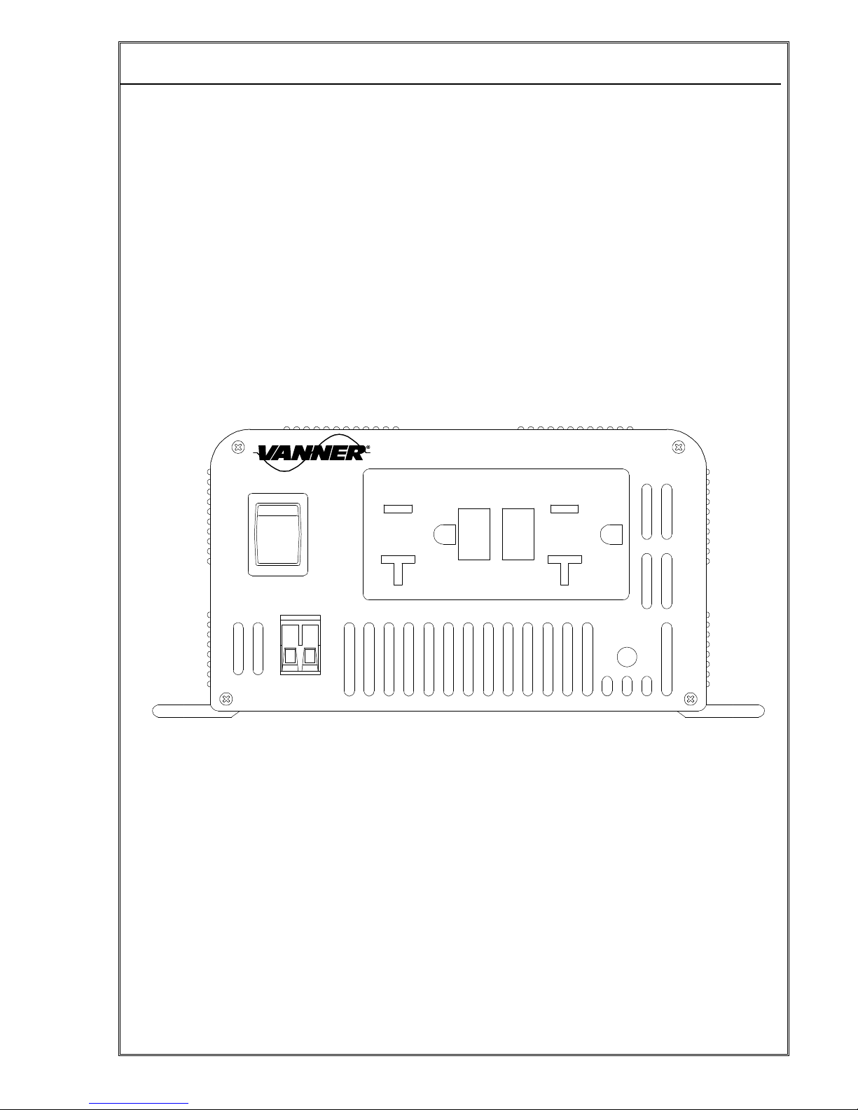
Owner’s Manual
300 Watt VLT Series Inverter Owner’s Manual - 9 -
4 Installation
4.1.1 Inverter Installation Considerations
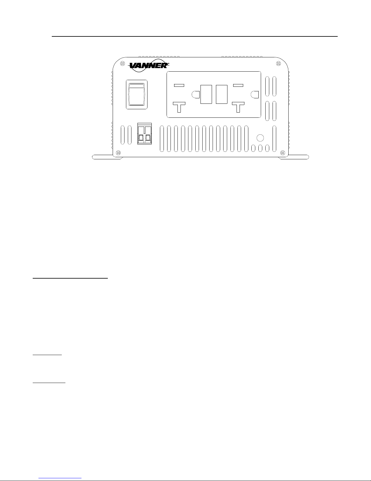
Mounting: Locate a flat secure, dry, horizontal or vertical surface large enough to mount the inverter. The
location should be as close to the battery as ractical, usually within six feet, but not in the same
com artment and should rovide adequate ventilation while the inverter is o erating. The location must
be clean, dry and free from road s ray, dri ing water or other moisture contamination.
Cooling Fan Clearance: The mounting location must allow unobstructed airflow for cooling. Allow a
minimum clearance of 3 inches on the front and back of the inverter. The Cooling Fan is thermostatically
controlled. Obstruction of the fan exhaust or the front intake vents will diminish the inverter out ut
ca acity due to overheating.
4.1.2 DC Wiring Considerations
Do not connect the 12V model to a 24V battery. The unit will be destroyed immediately. O eration
of the inverter without a ro er ground connection may result an electrical safety hazard. Damage caused
by reversed olarity will void warranty.
A DC FUS IS R QUIR D to rotect the DC cables in case of a short circuit. The wiring of the
inverter installation should conform to the National Electric Code (NEC) and any other state or local codes
in effect at the time of installation. Article 551 of the NEC requires any DC cable from a battery, which
measures longer than 18 inches along its length, be rotected by a fuse.
B AWAR , as a large number of ca acitors become charged u on com letion of the DC circuit,
TH R WILL B A LARG SPARK when the last battery connection is made. The s ark is normal and
will occur every time the batteries are connected. It is advisable to make the last DC connection at the
inverter, not at the battery, to reduce the risk of battery ex losion.
To minimize electromagnetic radiation that could interfere with sensitive electronics, route the AC out ut
wiring and DC ower wiring with as much hysical se aration as ossible from low voltage wiring such as
audio and video signal wires. Route the DC ositive and negative cables as close together as ossible
and use cable ties to kee them together.
If assing through steel or other ferrous metal walls, the DC in ut cables need to ass through the same
hole to revent causing a transformer effect. If two holes are required, cut a slot to connect the two holes
to revent heating of the ferrous metal.
Proper DC cable size is critical for the erformance and safe o eration of the inverter system.
The DC Cable and Fuse Sizing Chart shows the minimum cable sizes recommended. These sizes allow
a ½ volt maximum voltage dro at maximum inverter ca acity and will insure o timum inverter
erformance. DC cable to be used with these fuse sizes should be minimum insulation tem erature
rating of 105°C and voltage rating of 600V.
DC cables should be as short as ossible.
Do not use the vehicle chassis as the DC negative conductor. The negative cable should be the same
size as the DC ositive cable and should be connected directly to the battery negative terminal.