Riello BeSMART Operation and installation manual

Installer and User Manual
EN
Installer and User Manual
BeSMART
Thermostat | WiFi Box and boiler RF receiver
SET
PROG
RESET
ESC
MODE

2
Dear Customer,
Thank you for choosing the BeSMART control. This control device for heating
(and cooling) systems and boilers is easily installed and, if used correctly,
offers better quality comfort as well as energy savings.
This thermostat has been designed to support a maximum of 2 A at 30 VDC
or 0.25 A at 230 VAC (specifications for internal relay to switch the boiler
“room thermostat” connection).
9 If the device is installed by a third party, please ensure that this manual
is given to the end user.
9 These instructions must be kept by the user.
COMPLIANCE
The BeSMART remote control panel complies with:
−Electromagnetic Compatibility Directive 2014/30/EU
−Low Voltage Directive 2014/35/EU
The following symbols are used in some parts of the manual:
9
CAUTION= for tasks which require particular care and suitable preparation.
0FORBIDDEN = for tasks which MUST NOT be performed.

3
SUMMARY
1 GENERAL INFORMATION... 4
1.1 General notices ............4
1.2 What is the BeSMART for? ....5
1.3 Modes of use ..............6
1.4 Glossary of technical terms ... 6
1.5 BeSMART control Class
Declaration, according to the ErP
Directive ..................8
2 INSTALLATION ...........10
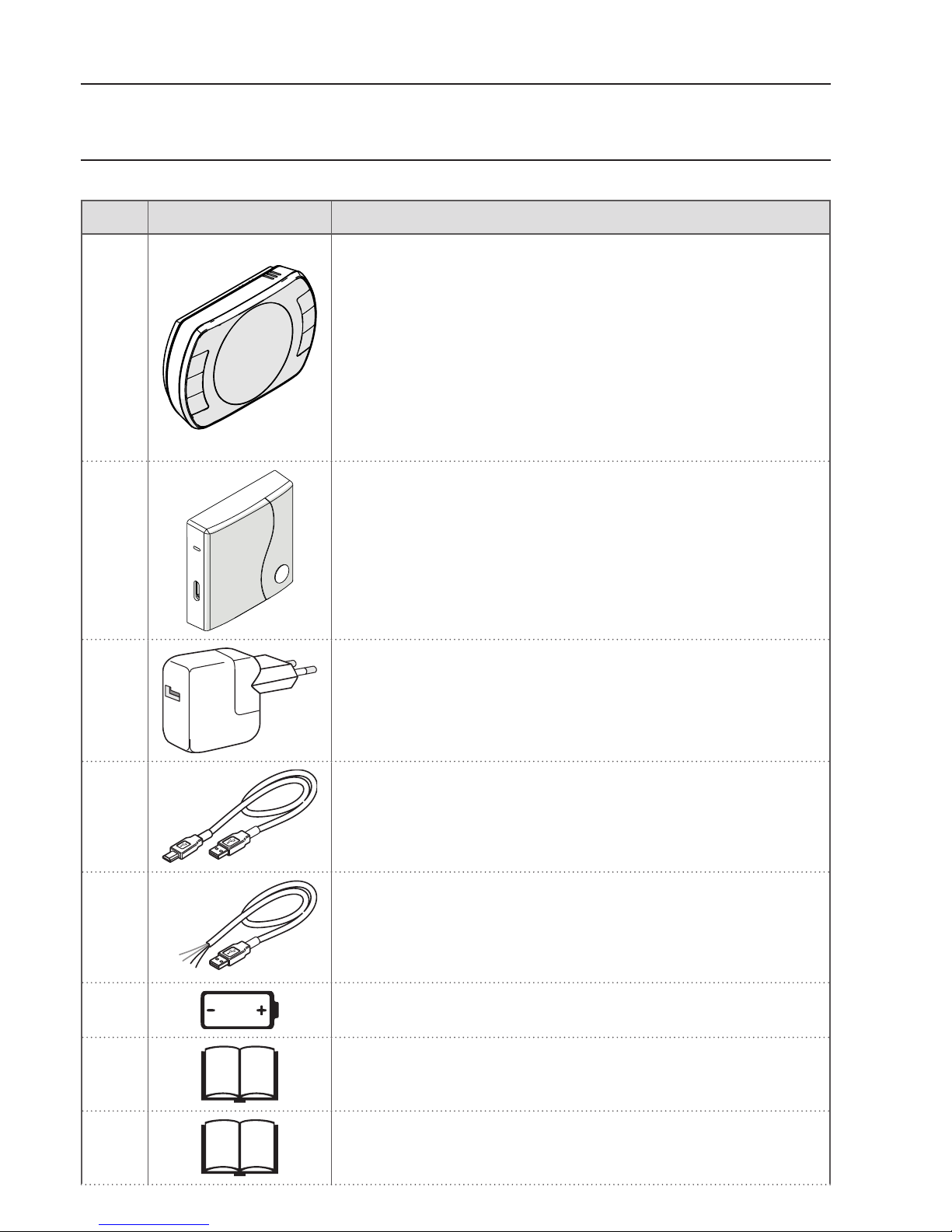
2.1 Contents of the package ....10
2.2 Practical installation diagrams 14
2.2.1 Diagram 1 .............14
2.2.2 Diagram 2 .............15
2.2.3 Diagram 3 .............15
2.2.4 Diagram 4 .............16
2.2.5 Diagram 5 .............17
2.2.6 Diagram 6 .............17
2.2.7 Diagram 7 .............18
2.2.8 Diagram 8 .............19
2.2.9 Diagram 9 .............20
2.2.10 Diagram 10 ............20
2.2.11 Diagram 11 ............21
2.2.12 Diagram 12 ............22
2.2.13 Diagram 13 ............23
2.2.14 Diagram 14 ............24
2.2.15 Diagram 15 ............25
2.2.16 Diagram 16 ............26
2.2.17 Diagram 17 ............27
2.2.18 Diagram 18 ............28
2.2.19 Diagram 19 ............29
2.2.20 Diagram 20 ............30
2.2.21 Diagram 21 ............31
2.2.22 Diagram 22 ............32
2.2.23 Diagram 23 ............33
2.3 Technical Data ............34
2.4 Dimensions ...............36
2.5 Three-phase installation .....37
3 COMMISSIONING......... 45
3.1 User interface .............45
3.2 Display ..................46
3.3 Setting the date and time ....47
3.4 Setting the heating/cooling ....
mode....................48
3.5 Setting the operating mode ..49
3.6 Setting the extra functions ...51
3.7 Setting the heating/cooling time
program in automatic operating
mode....................53
3.8 Setting the DHW time program55
3.9 Setting the heating/cooling room
setpoint temperature .......56
3.10 Setting the DHW setpoint
temperature ..............59
3.11 Displaying operating .........
information ...............59
3.12 Technical menu – Advanced
programming .............63
3.13 RF receiver configuration ....72
3.14 Linking function............72
4 ALARMS AND OPERATING
STATUSES...............75
4.1 LED notification lights for the WiFi
Box and boiler RF receiver **.75
4.2 Boiler and BeSMART alarms . 76

4
1 GENERAL INFORMATION
1.1 General notices
Please read this manual before installing and using the device.
9 Risk of electric shock. This device should be installed by a qualified
professional and in line with the standards in force for electrical installa-
tions. Always disconnect the power supply before installing.
9 Note to the installer:
−Most of the product parameters are factory set. If the device is ac-
tivated without a WiFi connection, the date and time should be set
on the thermostat as a minimum (this information is wiped every time
the batteries are removed and if not updated via the web). All other
settings – such as linking the receiver and the transmitter (for the WiFi
Box), usage mode and temperatures – are pre-configured.
9 These instructions must be read together with the sections of the boiler
manual regarding the room thermostat/boiler remote control. It is recom-
mended that the device be installed by qualified technicians.
9 The BeSMART should be installed in the most accessible room for you
as regards controlling the room temperature (usually the living room).
9 As per the standards, the BeSMART should be positioned 1.5 m from
the floor to make sure that you can easily read the display.
9 The BeSMART is powered by 2 x AA batteries.
9 The BeSMART must be kept away from sources of heat or air currents
as these may affect the accuracy of the readings from the incorporated
room sensor.
9 Do not open the BeSMART for any reason, unless to replace the batter-
ies; it does not require any maintenance to operate.
9 Do not press on the liquid crystal display glass as this may damage the
glass and cause problems with reading the display.
9 To clean the display, use a dry cloth only. Any seepage would damage
the liquid crystal display.

5
9 When the WiFi Box is connected in ON/OFF mode to the boiler or anoth-
er device via cable, should all the thermostats be faulty or the batteries
flat, the Box will show as OFF (no heating/cooling requests). The Wi-Fi
Box relay can be forced on and off manually using the APP.
9 With the WiFi Box connected in OTBus mode to the boiler via cable,
should all the thermostats be faulty or the batteries flat, the Box will
remain in the last operating mode. The boiler (in heating mode) can be
forced on and off manually using the APP.
9 With the BeSMART connected (ON/OFF) to the boiler or another device
via cable, should all the thermostats be faulty or the batteries flat, the
thermostat relay will remain in the last operating mode.
9 With the WiFi Box connected in ON/OFF or OTBus mode to the boiler
via cable, should there be a power outage, the WiFi box remains in the
last operating mode.
1.2 What is the BeSMART for?
The BeSMART allows you to check the temperature in your house and the
operation of your boiler without you needing to access it. For reasons of
space optimisation, your boiler may be located outside (for example, on a
terrace or balcony or in an outdoor space); the BeSMART, on the other hand,
is usually installed in the largest room in the house, where it can be easily
checked and adjusted.
Where installed in systems with a boiler which is not equipped with the spe-
cific communication bus, the BeSMART only allows you to check the temper-
ature in your house and does not allow you to control the boiler remotely (do-
mestic hot water temperature and boiler settings/alarms cannot be managed).
For both types of installation, the BeSMART system allows you to check the
temperature in different zones in your house, where there are zone valves
and each one of these is connected to a single additional BeSMART (mul-
ti-zone management).
If the BeSMART is installed together with the WiFi Box and you have a WiFi
internet connection in your home, the BeSMART system allows you to carry out
the same functions available via the BeSMART itself remotely on a smartphone.

6
1.3 Modes of use
The BeSMART means you can manage your domestic heating in a more so-
phisticated way; you can decide how and when the boiler will come on to heat
your living spaces. In addition, it allows you to set the domestic hot water tem-
perature, without having to access the boiler panel (where connected to the
boiler via OTBus or a specific communication bus). The purpose of this manual
is to explain each of these ways of using the device and the related functions.
1.4 Glossary of technical terms
Heating water: the water in the radiators that has been heated by the boiler.
Domestic hot water: the water heated by the boiler which is dispensed from
the domestic taps.
Fault code: this code shows on the display to flag any boiler or BeSMART faults.
Original set-up: this is the control panel configuration after turning on the
device for the first time or after a reset.
Display: this is the liquid crystal panel where each of the symbols corre-
sponding to the various functions are shown.
Anti-freeze function: this function ensures that any drops in temperature
do not cause the water inside the pipes to freeze and cause damage to the
heating system. This function is activated when the room temperature drops
below 5°C (this value can be changed by the qualied technical service).
NOTE
This function is active only if the boiler is in the correct operating condition
(i.e. powered and not blocked).
Restore factory settings: this restores the control panel to its original set-up,
resetting any user programming excluding the system clock.
Summer: the heating system is not active in this mode (for example, during
the summer).
The boiler can dispense domestic hot water. If correctly connected and con-
figured (in cooling mode), the BeSMART can be used to manage a cooling
system in the summer, turning the relay on in ON/OFF mode, in the opposite
way to the winter operating mode. The relay keeps the user request connect-
ed (e.g. a zone valve) until the room temperature falls below a certain level.
The cooling mode requires a specific system and generator for this purpose.
Winter: the BeSMART dispenses domestic hot water and hot water for heat-
ing in this mode.

7
T1 anti-freeze temperature: this is the temperature used when the rooms
are not lived in.
T2 economy temperature: this is the temperature used when the rooms are
not lived in during the day, at night or when you are on holiday.
T3 comfort temperature: this is the temperature at which you obtain ideal
room heating during the day.
Room temperature: this is the temperature in the room where the BeSMART
is installed (see "NOTE 1" to page 8).
Room setpoint temperature: this is the desired room temperature.
External temperature: this is the temperature outside, read using an external
probe connected to the boiler or read in another way (see "NOTE 2" to page 8).
Heating curve: this is the relationship between the external temperature and
the heating flow temperature. Where external temperature data are available
(via an external probe or other method), the heating flow temperature is au-
tomatically adjusted as the external temperature varies in order to maintain
a constant temperature in the room. The heating curve must be set by the
installer on the basis of the geographical location and type of system.
Connection via OTBus communication bus: this is a communication mode
between the BeSMART and the boiler, where a series of information is ex-
changed between the two electronic systems. This proprietary connection
can be used as opposed to the simple ON/OFF (open/closed contact) and is
set by the boiler manufacturer specifically for the BeSMART.
Check the compatibility of your boiler with the OTBus connection first.
ON/OFF connection (boiler room thermostat): this is the simple commu-
nication method between the BeSMART and the boiler (or any other unit
capable of receiving this command), where the relay on the BeSMART (or on
the WiFi Box/receiver) sends an on/off request via the room thermostat (TA)
contact on the boiler. The ON/OFF connection is also used when a request is
made to another system component such as a zone valve or similar.

8
The BeSMART ON/OFF contact always maintains the same technical char-
acteristics (BeSMART relay, WiFi Box relay, boiler RF receiver relay) wherev-
er it is positioned and these must be respected when connecting the relay
and the components it controls via cable. NOTE: Never exceed the maximum
electrical loads.
NOTE 1
The display range for the room temperature is between -7°C and +50°C.
NOTE 2
The display range for the external temperature is between -40°C and +60°C.
Temperatures outside of these ranges are shown as three dashes “- - -”.
1.5
BeSMART control Class Declaration, according to the ErP Directive
With reference to Delegated Regulation (EU) No. 811/2013, the data in the ta-
ble can be used to complete the product data sheets and energy labelling of
space heaters, combination heaters, packages of space heater, temperature
control devices and solar devices.
Manufacturer/Brand Model
RIELLO SpA / BeSMART BeSMART
Possible BeSMART configurations, the relative configuration classes and the
energy contribution to the system.
Boiler
characteristics BeSMART conguration
Class and
contribution
Boiler with fixed
delivery temper-
ature (ON/OFF
control)
BeSMART ON/OFF connection I = 1%
Boiler with
variable delivery
temperature
(controlled by
communication
bus)
Connection via communication bus to
the BeSMART. Delivery temperature to
the boiler calculated on the basis of one
room temperature only
V = 3%
Boiler with
variable delivery
temperature
(controlled by
communication
bus)
Connection via communication bus to the
BeSMART. Delivery temperature to the
boiler calculated on the basis of the room
temperature and the external temperature
(given by the external probe or via the web).
VI = 4%

9
Boiler
characteristics BeSMART conguration
Class and
contribution
Boiler with
variable delivery
temperature
(controlled by
communication
bus)
Connection via communication bus to the
BeSMART. Delivery temperature to the
boiler calculated on the basis of at least
3 distinct room temperatures. At least 3
BeSMARTs (sensors) connected to at least
3 zone valves (actuators) are required.
VIII = 5%
Denition of classes
Class I – On/off room thermostat: a room thermostat that controls the on/off
operation of a heater. Performance parameters, including switching differen-
tial and room temperature control accuracy are determined by the thermo-
stat's mechanical construction.
Class V – Modulating room thermostat, for use with modulating heaters: an
electronic room thermostat that varies the flow temperature of the water leav-
ing the heater dependent upon measured room temperature deviation from
room thermostat set point. Control is achieved by modulating the output of
the heater.
Class VI – Weather compensator and room sensor, for use with modulating
heaters: a heater flow temperature control that varies the flow temperature of
water leaving the heater dependent upon prevailing outside temperature and
selected weather compensation curve. A room temperature sensor monitors
room temperature and adjusts the compensation curve parallel displacement
to improve room comfort. Control is achieved by modulating the output of
the heater.
Class VIII – Multi-sensor room temperature control, for use with modulating
heaters: an electronic control, equipped with 3 or more room sensors, that
varies the flow temperature of the water leaving the heater dependent upon
the aggregated measured room temperature deviation from room sensor set
points. Control is achieved by modulating the output of the heater.

10
2 INSTALLATION
2.1 Contents of the package
The WiFi BeSMART package contains the following components:
Qty Component Description
1
BeSMART = boiler remote control with room
programmable thermostat function (*) or room
programmable thermostat (**).
(*) where there is an active OTBus connection in one of the
following configurations: between the WiFi Box and the
boiler, between the RF receiver (optional) and the boiler,
between the BeSMART and the boiler,
(**) where the TA connection between the WiFi Box and the
boiler is active
1
WPS/Smartlink Outputs Boiler
WiFi Box = device for communicating with the
BeSMART programmable thermostat. It can
operate with the boiler RF receiver (optional) via
radio frequency, with the boiler itself via cable
(provided as standard) and with your home rout-
er via a WiFi connection. Magnetic back so that
it can be attached to the boiler’s metal casing.
1USB power adapter
1
USB cable A – USB Mini B = WiFi Box power cable
1USB cable A = cable connecting the WiFi Box
and the boiler
21.5V AA batteries
2Quick guide
1Installer/User Manual

11
Qty Component Description
2Screws with plugs
1
OTBus connector (only for boilers without one)
for an OTBus connection between the WiFi Box
and the boiler or the boiler RF receivers (optional)
and the boiler or the BeSMART and the boiler. It
can also be used to connect the external probe
(optional).
9 If installing additional BeSMARTs or boiler RF receivers, you must follow
the procedure to link them to the WiFi Box (see "3.14 Linking function"
to page 72).
The BeSMART package contains the following components:
Qty Component Description
1
BeSMART = boiler remote control with room
programmable thermostat function (*) or room
programmable thermostat (**).
(*) where there is an active OTBus connection in one of the
following configurations: between the WiFi Box (optional)
and the boiler, between the RF receiver (optional) and
the boiler, and between the BeSMART and the boiler,
(**) where the TA connection between the WiFi Box (optional)
and the boiler is active
2 1.5V AA batteries
1Quick guide
1Installer/User Manual
2Screws with plugs
9 If installing additional BeSMARTs or boiler RF receivers, you must follow
the procedure to link them to the WiFi Box (see "3.14 Linking function"
to page 72).

12
The WiFi Box kit contains the following components:
Qty Component Description
1
WPS/Smartlink Outputs Boiler
WIFI Box
1 USB power adapter
1
USB cable A – USB Mini B = WiFi Box power cable
1USB cable A = cable connecting the WiFi Box
and the boiler
1Quick guide
1Installer/User Manual
9 If installing additional BeSMARTs or boiler RF receivers, you must follow
the procedure to link them to the WiFi Box (see "3.14 Linking function"
to page 72).

13
The Boiler RF receiver kit contains the following components:
Boiler RF receiver
Qty Component Description
1Boiler RF receiver
1Quick guide
9 If installing additional BeSMARTs or boiler RF receivers, you must follow
the procedure to link them to the WiFi Box (see "3.14 Linking function"
to page 72).

14
2.2 Practical installation diagrams
Key
RF
Radio frequency communication (868 MHz)
WiFi
WiFi communication (2.4 GHz)
WiFi modem/router
Internet connection
Smartphone/Tablet (Android/IOS)
LLine
NNeutral
TA
Room thermostat connection, dry contact ON/OFF (max 0.25 A @ 230 V)
OT
OTBus protocol connection, contact for proprietary communication protocol
Zone valve without limit switch
Zone valve with limit switch
2.2.1
Diagram 1
ON/OFF programmable thermostat for heating (TA).
Single heating zone in ON/OFF mode.
SET
PROG
RESET
ESC
MODE
BeSMART
TA
TA

15
2.2.2
Diagram 2
ON/OFF programmable thermostat for heating (TA).
Multi-zone heating in ON/OFF mode.
9 Up to 8 areas if WiFi Box is available.
Up to 7 areas with boiler RF receiver connected to the boiler.
For information on wireless management of the zone valves, please
see "Diagram 16" - "Diagram 17"
SET
PROG
RESET
ESC
MODE
SET
PROG
RESET
ESC
MODE
SET
PROG
RESET
ESC
MODE
BeSMART
zona 1 zona ...
zona ...
BeSMART BeSMART
TA
TA
TA
L
N
TA
2.2.3
Diagram 3
Modulating programmable thermostat/remote control.
Single heating zone in modulating thermoregulation mode.
OT: full control of boiler, heating, DHW, alarms and settings.
OT
SET
PROG
RESET
ESC
MODE
BeSMART
OT

16
2.2.4
Diagram 4
Modulating programmable thermostat/remote control and ON/OFF pro-
grammable thermostat for heating (TA).
Single zone in modulating thermoregulation mode.
OT: full control of boiler, heating, DHW, alarms and settings.
Multi-zone heating in ON/OFF mode.
TA
OT
SET
PROG
RESET
ESC
MODE
SET
PROG
RESET
ESC
MODE
SET
PROG
RESET
ESC
MODE
BeSMART
zona 1 zona ... zona ...
BeSMART BeSMART
TA
TA
TA
L
N
9
Set the boiler to “zone valve” mode. Request procedure from
Technical Assistance Centre.
9 Up to 8 areas if WiFi Box is available.
Up to 7 areas with boiler RF receiver connected to the boiler.
For information on wireless management of the zone valves, please
see "Diagram 16" - "Diagram 17"

17
2.2.5
Diagram 5
ON/OFF programmable thermostat for heating (TA).
Single heating zone in ON/OFF mode.
Wireless installation.
9 Only one BeSMART can be connected to the boiler RF receiver.
230 V
SET
PROG
RESET
ESC
MODE
BeSMART
RF
TA
Boiler RF
receiver
2.2.6
Diagram 6
Modulating programmable thermostat/remote control.
Single heating zone in modulating thermoregulation mode.
OT: full control of boiler, heating, DHW, alarms and settings.
Wireless installation.
9 Only one BeSMART can be connected to the boiler RF receiver.
SET
PROG
RESET
ESC
MODE
BeSMART
RF
230 V
OT
Boiler RF
receiver

18
2.2.7
Diagram 7
ON/OFF programmable thermostat for heating (TA) with remote control
via WiFi.
Single heating zone in ON/OFF mode.
SET
PROG
RESET
ESC
MODE
WiFi Box
RF
BeSMART
BeSMART
serverinternet
WiFi WiFi
230 V
TA
TA

19
2.2.8
Diagram 8
Modulating programmable thermostat/remote control with remote con-
trol via WiFi.
Single heating zone in modulating thermoregulation mode.
OT: full control of boiler, heating, DHW, alarms and settings.
OT
SET
PROG
RESET
ESC
MODE
WiFi Box
RF
BeSMART
serverinternet
WiFi WiFi
230 V
OT
BeSMART
CANNOT BE DONE

20
2.2.9
Diagram 9
ON/OFF programmable thermostat for heating (TA) with remote control
via WiFi.
Wireless installation.
TA
SET
PROG
RESET
ESC
MODE
BeSMART
WiFi Box
BeSMART
serverinternet
WiFi WiFi
RF
RF
230 V
2.2.10
Diagram 10
Modulating programmable thermostat/remote control, , with remote con-
trol via WiFi.
Single heating zone in modulating thermoregulation mode.
OT: full control of boiler, heating, DHW, alarms and settings.
Wireless installation.
OT
SET
PROG
RESET
ESC
MODE
BeSMART
WiFi Box
BeSMART
serverinternet
WiFi WiFi
RF
RF
230 V
Other manuals for BeSMART
2
Table of contents
Other Riello Thermostat manuals

Riello
Riello BeSMART User manual

Riello
Riello CDI 15 User manual

Riello
Riello Hi, Comfort 100 Operation and installation manual

Riello
Riello ricloud User manual

Riello
Riello ricloud User manual

Riello
Riello RiCLOUD NA Series User manual

Riello
Riello Hi, Comfort T100 Operation and installation manual

Riello
Riello BeSMART User manual