manuals.online logo
Brands
  1. Home
  2. •
  3. Brands
  4. •
  5. Riello
  6. •
  7. Thermostat
  8. •
  9. Riello BeSMART User manual

Riello BeSMART User manual

Rapida
Quick start guide
IT Guida
Rapida
EN
Quick start guide
BeSMART WiFi Thermostat
1L’installazione viene fatta in 3 fasi
Installation is done in 3 steps
B CA
Installa il termostato BeSMART
Install the BeSMART thermostat
Installa il wifi box
Install the wifi box
S ari a la APP BeSMART
ownload the BeSMART APP
Preparazione
Preparation
Prima dell’installazione
•Verifi are he il termostato sia ompatibile on la aldaia ( onsultare manuale installatore aldaia).
•Il termostato BeSMART wireless può essere installato ovunque, è tuttavia onsigliabile stabilire il
punto più idoneo (vedi immagini orrelate). L’installazione wireless non ne essita di ablaggio
pertanto l’operazione risulta estremamente sempli e.
•Il termostato BeSMART può essere installato an he ablato in sostituzione di un qualsiasi
termostato già esistente, previa verifi a della ompatibilità ( onsultare manuale installatore
BeSMART).
•Prima di pro edere all’installazione del modulo di omando della aldaia (WiFi Box) interrompere
l’alimentazione della aldaia.
Durante l’installazione
Sono ne essari i seguenti attrezzi:
•
Ca iavite
a
ro e
.
Evitare
orrenti
d’aria
Non
installare
sopra
fonti
di
alore
•
Ca iavite
a
ro e
.
•Pi olo a iavite a taglio.
•Pinza e pinza spella fili.
Before installation
•Refer to the appliance manual to ensure that the BeSMART thermostat is compatible with your
boiler
•The BeSMART wireless thermostat can be installed almost everywhere within the home, however
please refer to the adjacent diagrams for guidance when deciding on a suitable location.
•The BeSMART thermostat can also be used to replace an existing hard-wired thermostat (please
check appliance manual to ensure compatibility).
•Switch off and isolate the appliance and any external controls from the electrical supply, before
carrying out the installation.
Tools required for the installation
•Phillips screwdriver
•Small flat blade screwdriver
•Combination pliers
Evitare
orrenti
d’aria
Avoid draughty areas
Non
installare
sopra
fonti
di
alore
o not install above heat sources
Evitare lu e diretta del sole
Avoid dire t sunlight
Posizionare ad altezza adeguata
Install at the correct height
Installazione del BeSMART
BeSMART Installation
A
3
Se ne essario rimuovere il ve hio appare hio.
If necessary remove the old thermostat.
Attenzione: il BeSMART non ne essita di essere ablato
per hè wireless. Si onsiglia di isolare i avi e farli rientrare
nella parete. Nel aso di installazione ablata, verifi are la
ompatibilità ( onsultare manuale installatore BeSMART)
e pro edere al ollegamento.
Attention: The BeSMART thermostat is a wireless control.
Isolate any redundant wiring and ensure it does not
interfere
with
the
fitment
of
the
BeSMART
control
.
If
its
Separare il BeSMART dalla sua base.
Separate the BeSMART from the wall plate.
interfere
with
the
fitment
of
the
BeSMART
control
.
If
its
intended to re-use any existing wiring; you should refer to
the appliance manual to ensure compatibility .
Fissare la base del BeSMART
alla parete o alla s atola elettri a
utilizzando le viti a orredo (testa
della vite dentro propria sede).
Fix the wall plate to the wall
using the supplied screws.
(screw head inside proper
location)
Installazione cablata / hard-wired installation
Collegare i avi del termostato ambiente di aldaia o l’alimentazione
dell'’eventuale valvola di zona al morsetto TA del BeSMART.
If using as a hard-wired control; connect the respective wiring to the
relevant terminals on the BeSMART control.
TA
ON/OFF
Attenzione: per i ollegamenti elettri i e le
spe ifi he te ni he vi invitiamo a onsultare il
manuale installatore del BeSMART.
Attention: Please refer to the appliance
installation manual and the BeSMART manual
for specific information on hard-wired
connections.
Installazione del BeSMART
BeSMART Installation
A
4
Montare il BeSMART sulla sua base sempli emente premendo
leggermente sullo stesso.
Re-attach the BeSMART thermostat to the wall plate by aligning
and then pressing firmly around the outer edges.
Inserire le due batterie di tipo AA fornite a
orredo, nell’apposito alloggiamento.
Insert two ‘AA’ type batteries (supplied),
into the battery compartment .
Attenzione: inserire le batterie on la
orretta polarità ome indi ato in figura.
Attention: insert the batteries, observing
the correct polarity as indicated.
Installazione del WiFi Box
WiFi Box Installation
B
5
In aso di installazione non ablata, ollegare i fili del avo USB al
morsetto OT-Bus (solo per spe ifi he aldaie) oppure al TA (Termostato
Ambiente-ON/OFF) della aldaia.
Case installation wireless, connect the (supplied) USB cable to the boiler
OT-Bus connection (for specific boilers) or to the boiler room thermostat
connection (TA or ON/OFF).
Appli are il WiFi Box sul mantello metalli o della aldaia
mediante magnete presente sul retro dello stesso (si
onsiglia di verifi are la minima temperatura esterna di
installazione riportata sul manuale installatore del
BeSMART).
In aso di installazione non ablata, segnale WiFi
debole e utilizzo del dell’a essorio ri evitore aldaia,
posizionare il WiFi Box in ambiente ove il segnale WiFi
non sia debole ( onsigliato sopra 30%). Attach the
WiFi box to the appliance casing, using the magnetic
pad located on the rear of the WiFi Box. Please check
the ambient temperature is according the product
specification
as
indicated
on
the
installation
manual
.
In
Attenzione: per i ollegamenti elettri i e le spe ifi he te ni he vi invitiamo a
onsultare
il
manuale
installatore
di
aldaia
(
onnettore
OT
per
spe ifi he
aldaie
USB
TA = nero/Bla k
OT = rosso/red
specification
as
indicated
on
the
installation
manual
.
In
case of installation wireless, low WiFi signal and boiler
RF receiver installed, place the WiFi Box in an ambient
with a good WiFi signal (above 30%)
onsultare
il
manuale
installatore
di
aldaia
(
onnettore
OT
per
spe ifi he
aldaie
fornito a orredo)
Attention: for the electrical connection and the technical specifications, please refer
to the installation manual. (OT PCB plug supplied as standard)
In aso di installazione non ablata, ollegare la
spina USB del avo pre edentemente ollegato
alla aldaia nell’us ita OUTPUTS/BOILER del
WiFi Box.
In case of wireless installation, insert the other
end of the USB cable into the
OUTPUTS/BOILER socket of the WiFi Box.
USB
USB mini B
Alimentare il WiFi Box tramite
l’apposito avo e alimentatore
forniti a orredo.
Using the mini USB cable and
power adaptor (supplied);
connect the WiFi box to an
adjacent electrical socket .
Outputs/Boiler
CInstallazione e onfigurazione della APP per smartphone
Installation and configuration of smartphone APP
S ari are e installare la APP
BeSMART sul proprio
Smartphone o tablet.
ownload and install the
BeSMART app on your
Smartphone or tablet.
6
Creare un a ount utente
seguendo tutti i passaggi
indi ati sulla app.
Create a user account following
the steps indicated on the app.
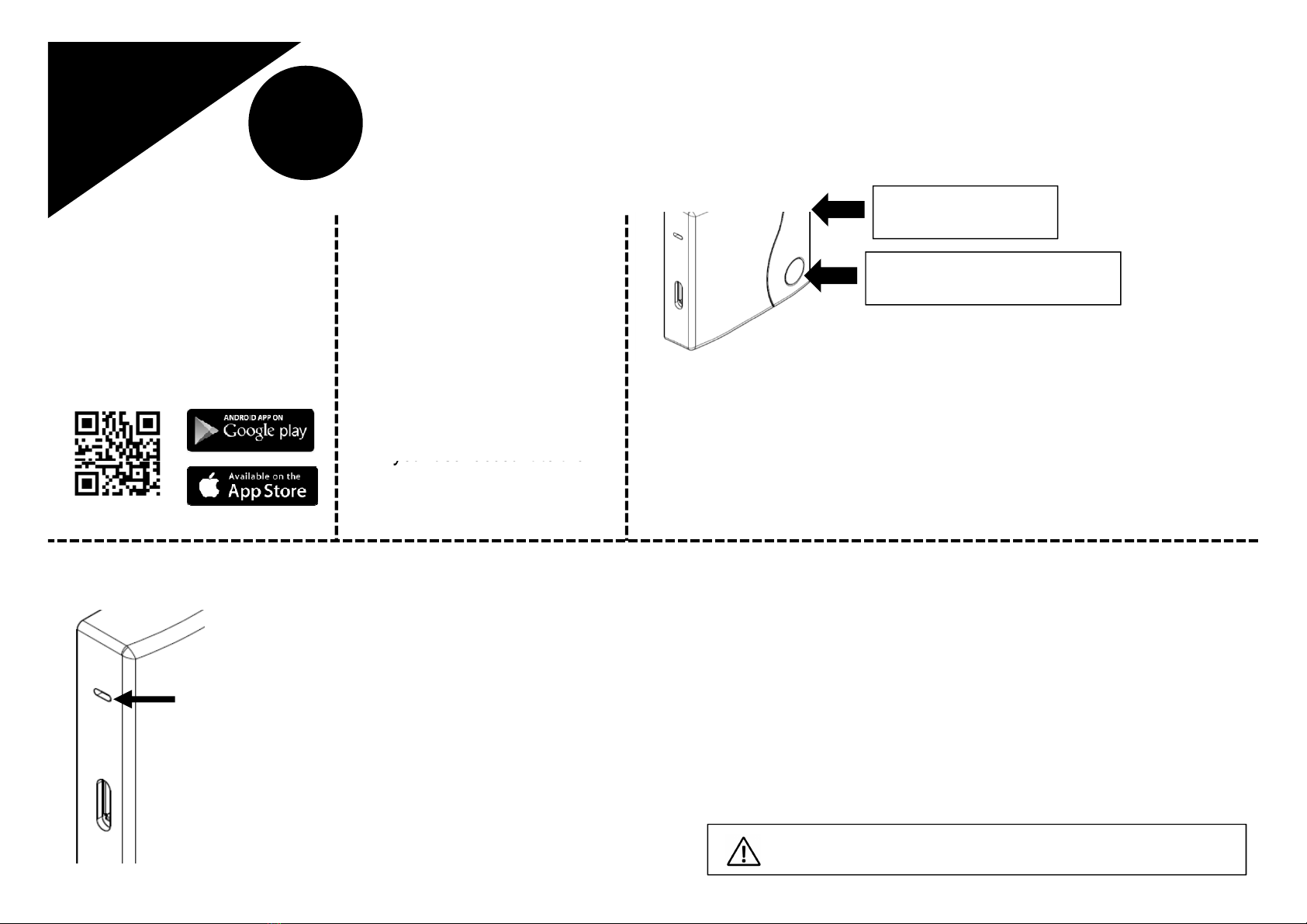
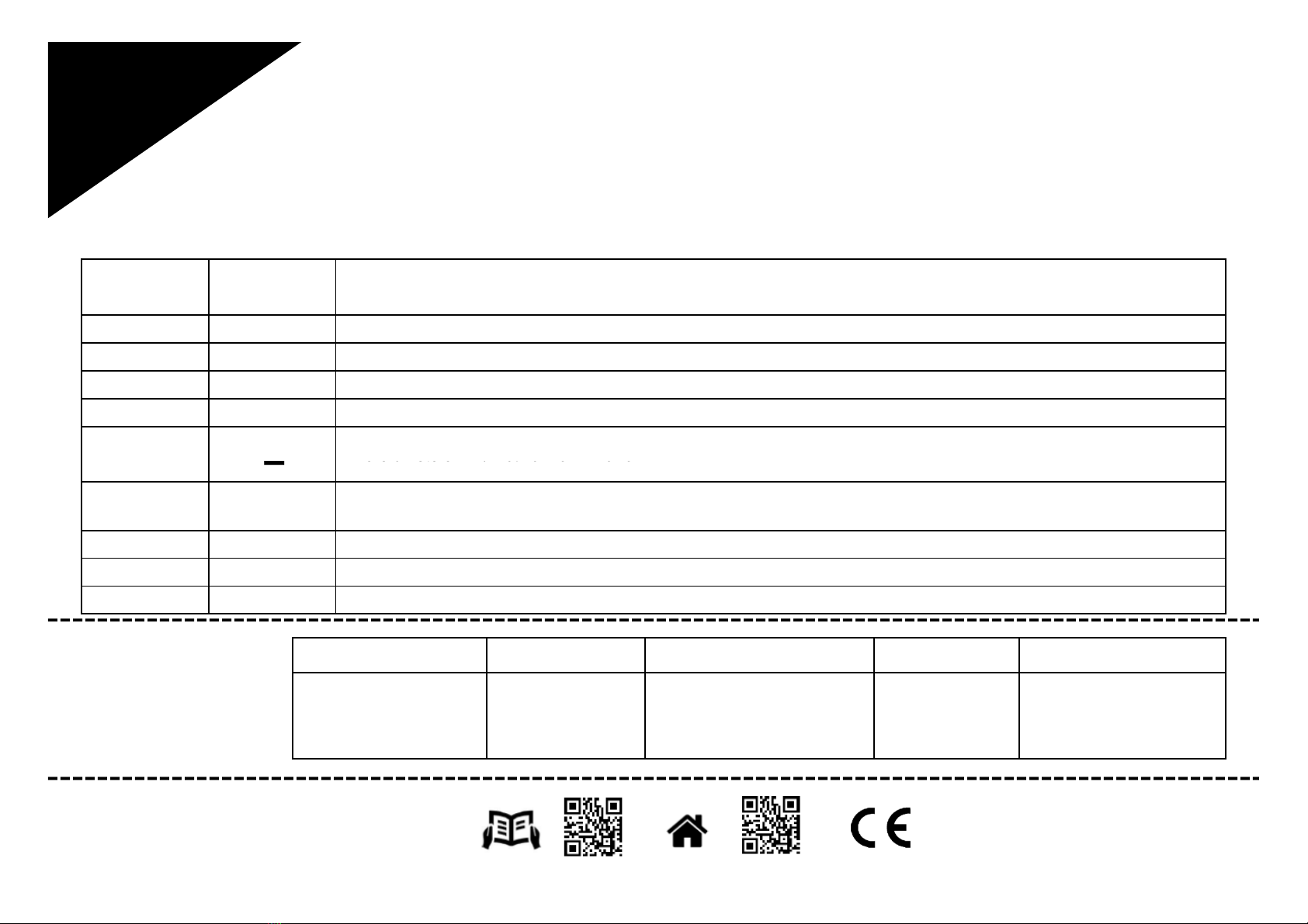
Abbinare il odi e ID WiFi del
WiFi Box all’a ount.
Link your user account to the
MAC : 000000000000
ID WIFI : 0000000000000
Outputs/Boiler
WPS / Smartlink
Se ne essario abbinare in radio frequenza (RF) al WiFi Box altri termostati e/o ri evitore RF
aldaia, premere per 5 se ondi il tasto trasparente sul WiFi Box fino al lampeggio ontemporaneo
dei LEDs e mettere nella medesima modalità la ontroparte da abbinare (vedi manuale).
Terminato l’a oppiamento automati amente il sistema si riporta alla normalità.
If required, it is possible to couple a boiler receiver or additional thermostats to the WiFi box using
the
following
procedure
:
press
and
hold
the
wifi
LE
button
on
the
WiFi
box
until
both
red
and
Tasto trasparente a bolla prismati a /
WiFi LE button
Link your user account to the
‘ID WiFi’ code that’s located
on the side of the WiFi Box.
Asso iare la password del proprio modem di asa al WiFi Box s egliendo una delle seguenti modalità.
Use the password key of your ‘WiFi’ router to link the WiFi Box to your home network using one of the methods indicated below.
Smart Link:
•Premere 1 volta il tasto Smart Link sul WiFi Box on uno strumento
adeguato.
•Il led verde inizia a lampeggiare velo emente.
•Selezionare il ampo “Configura il WiFi” nel menu a tendina della APP,
inserire la password del modem di asa e premere il tasto “Collegati”.
•L’asso iazione è on lusa se la APP mostra l’avviso “ ollegamento
effetuato on su esso”
Press once the Smart Link button with a paper clip or similar .
The green LE should be flashing rapidly
Start the smart link function on the app (WiFi configuration menu) enter
the network password – WiFi box will automatically configure
WPS: (solo per modem provvisti di questa funzione – only for router with WPS
functionality)
•Mettere in modalità WPS il modem di asa.
•Premere a lungo il tasto WPS sul WiFi Box on uno strumento adeguato fino
a quando i led rosso e verde dello stesso, lampeggiano velo emente.
•L’asso iazione è on lusa se, dopo po hi se ondi, il led rosso del WiFi Box
lampeggia velo emente.
Enable the WPS function via your router/home network
Press and hold the WPS button on the WiFi box with a paper clip or similar,
until the green and red LE s are flashing rapidly and consecutively.
Successful activation is confirmed when the red LE flashes rapidly
WPS / Smartlink Outputs/Boiler
the
following
procedure
:
press
and
hold
the
wifi
LE
button
on
the
WiFi
box
until
both
red
and
green LE s are flashing simultaneously. place the item that is to be coupled, into the ‘coupling’
mode. when the coupling process has been completed, the system will automatically return to the
normal operating condition.
Il sistema, un volta on-line, impiega fino a 4 minuti per auto onfigurarsi
The system, once online, may take up to 4 minutes for self configuration
Allarmi e stati di funzionamento
Alarms and working status
7
Lista segnalazioni LEDs del WiFi Box e relativa spiegazione.
Explanation of status LE s displayed on WiFi Box.
Cod. 20xxxxxx - 12/15 - Ed. 0
LED
= Fisso a eso /Fixed ON
 = lampeggiante velo e/flashing fast (0,5 se s)
 = lampeggiante lento/flashing slow (1 se s)
LED
verde/green
LED
rosso/red Stato/Status
 Rele = hiuso/bridged (solo per ollegamento ON/OFF - only with ON/OFF installation)
 Rele = aperto/open (solo per ollegamento ON/OFF - only with ON/OFF installation)
OT-bus ollegamento/ connection = OK (per ollegamento OT/OT onne tion)
  Allarme aldaia/Boiler alarm (solo per ollegamento OT/OT onne tion)



Errore di rete o RF /
Network or RF
error
Lista allarmi BeSMART e
relativa azione onsigliata.
Alarm codes indicated on the
BeSMART display and
suggested corrective actions.
Ulteriori informazioni e ri hiesta di assistenza al seguente sito:
More info and technical support at the following website:
www.besmart-home. om
BeSMART è un brand RIELLO GROUP
BeSMART is a RIELLO GROUP brand
Via Ing. Pilade Riello, 7
37045 Legnago - Italy
Err E8 E83 E84 A01….99
Sensore temperatura
danneggiato irreparabilmente.
Temperature sensor broken
(not reparable)
Errore radio frequenza.
Radio frequency error.
(Batteries/distance)
Man anza onnessione OT-bus.
NO OT-bus comunication.
(verifica/check connections)
Problemi hardware.
Hardware problems.
(not reparable)
Allarme di aldaia.
Boiler alarm..
(ref. caldaia/boiler manual)


Errore di rete o RF /
Network or RF
error
  Modalità WPS attiva – attendere segnale WPS dal router / WPS mode in progress (press and hold WPS button) – wait
WPS signal
 Segnale WPS a ettato / WPS signal detected
  Modalità Smartlink attiva / Smartlink mode in progress (press once Smartlink button)
  Modalità odifi a RF attiva / RF encoding in progress (press and hold the WiFi LE button)

Other manuals for BeSMART

2

Other Riello Thermostat manuals

Riello RiCLOUD NA Series User manual

Riello

Riello RiCLOUD NA Series User manual

Riello BeSMART User manual

Riello

Riello BeSMART User manual

Riello Hi, Comfort 100 Operation and installation manual

Riello

Riello Hi, Comfort 100 Operation and installation manual

Riello BeSMART Operation and installation manual

Riello

Riello BeSMART Operation and installation manual

Riello ricloud User manual

Riello

Riello ricloud User manual

Riello Hi, Comfort T100 Operation and installation manual

Riello

Riello Hi, Comfort T100 Operation and installation manual

Riello CDI 15 User manual

Riello

Riello CDI 15 User manual

Riello ricloud User manual

Riello

Riello ricloud User manual

Popular Thermostat manuals by other brands

Airzone OneZone user manual

Airzone

Airzone OneZone user manual

Honeywell Home THR842D user guide

Honeywell Home

Honeywell Home THR842D user guide

JUMO EM Series operating manual

JUMO

JUMO EM Series operating manual

Salus RT200 instruction manual

Salus

Salus RT200 instruction manual

Salus RT510 Full user manual

Salus

Salus RT510 Full user manual

Honeywell VVT user manual

Honeywell

Honeywell VVT user manual

Danfoss MTD Installation instructions and user guide

Danfoss

Danfoss MTD Installation instructions and user guide

Aube Technologies TH131 owner's guide

Aube Technologies

Aube Technologies TH131 owner's guide

alre RFHSU-010 manual

alre

alre RFHSU-010 manual

Daikin DZK-MTS-3 instructions

Daikin

Daikin DZK-MTS-3 instructions

Honeywell T7200D Product data

Honeywell

Honeywell T7200D Product data

Drayton Combi-Stat RTS8 installation instructions

Drayton

Drayton Combi-Stat RTS8 installation instructions

Sinope TH1120RF-3000 manual

Sinope

Sinope TH1120RF-3000 manual

ClimateMaster ATC32U01 iGate Basic operation guide

ClimateMaster

ClimateMaster ATC32U01 iGate Basic operation guide

ritetemp 8030 Operation guide

ritetemp

ritetemp 8030 Operation guide

tempio HY 312 user manual

tempio

tempio HY 312 user manual

Grohe Grohtherm 3000 Cosmopolitan 19 464 manual

Grohe

Grohe Grohtherm 3000 Cosmopolitan 19 464 manual

Charmeg MP-TM user manual

Charmeg

Charmeg MP-TM user manual

manuals.online logo
manuals.online logoBrands
  • About & Mission
  • Contact us
  • Privacy Policy
  • Terms and Conditions

Copyright 2025 Manuals.Online. All Rights Reserved.