Ries Hitachi Highly WHP01100PSV-H3EUN User manual

HitachiHighly
Rollkolbenverdichter
Rotary Compressors
Spezifikation
Installation Manual
WHP01100PSV-H3EUN
RIES GmbH, Rudolf-Diesel-Str. 10, D 64569 Nauheim, GERMANY

Table of Contents
First WHP01100PSV-H3EUN Specifications 1~4
1. Applications
2. Compressor Specifications
3. Parts list and drawings
4. General Characteristics
Second, the dedicated compressor heat pump water
heater using a reference 5-12
1. System design constraints
2. Process limits
3. other
Third, acceptance 13
1. Basis for acceptance
2. Acceptance rules
Fourth, drawing
Fifth, experience modification
14~22
23

SUBJECT
Model WHP01100PSV-H3EUN SPECIFICATION PAGE:1/23
1. SCOPE
This specification is applied to SHANGHAI HITACHI Heat pump water heater compressor.
2. SPECIFICATION OF COMPRESSOR
2.1 Model
WHP01100PSV-H3EUN
2.2 Rated Voltage/Frequency/Phase 220V~240V/50Hz/single
2.3 Application Heat pump water heater
2.4 Refrigerant R-290
2.5 Compressor Cooling Forced air
2.6 Displacement 5.86ml/rev
2.7 Performance
Performance (Voltage 220~240V)
Item Standard Condition Summer Condition Winter Condition Rated Condition
Nominal Heating Capacity 1173W/1200W 1347W/1384W 872W/910W 1128W/1164W
Motor input 307W/332W 307W/334W 300W/330W 303W/332W
Current 1.45A/1.47A 1.45A/1.45A 1.4A/1.43A 1.43A/1.45A
COP(see*) 3.82/3.61 4.39/4.14 2.91/2.76 3.72/3.51
Test Conditions
Evaporating temp. 10℃ 15℃ 0℃ 7.2℃
Condensing temp. 55℃ 55℃ 55℃ 54.4℃
Liquid temp. entering
expansion valve. 46.7℃ 46.7℃ 46.7℃ 46.1℃
Return gas temp. 20℃ 25℃ 10℃ 35℃
Ambient temp. 35℃ 35℃ 15℃ 35℃
Wind speed 2m/s 2m/s 2m/s 2m/s

SUBJECT
Model WHP01100PSV-H3EUN SPECIFICATION PAGE:2/23
*COP=
Heating capacity (W)
Motor input
2.8 Allowable amount of
refrigerant charge
2.9 Amount of oil charge
2.10 Oil
150 g
152±5 ml(Initial)
5GSD-TB or equivalent
2.11 Space volume of inner case
2.12 Net weight
2.13 Hermetic Terminal
380 ml
5.62 kg incl.oil
1/4”quick connect type
2.14 Motor Type Permanent Split Capacitor
Capacitor 12MFD/450 Volts
Locked rotor amps 6.1A (240V/50Hz)
Approved voltage range Rated Voltage(-10%,+10%)
Winding resistance(M/S) 14.09/19.37Ω(at 20℃)
2.15 Starting performance
(1) The starting voltage should be as follows.
(2) The starting pressure should be balanced between the suction and
discharge of the compressor and should be adjusted to the
following table.
(3) The temperatures of the compressor enclosure should be more than 20°C continiously
at the following table.

SUBJECT
Model WHP01100PSV-H3EUN SPECIFICATION PAGE:3/23
Starting Performance (1) Starting voltage shown in Table 1.
(2) Starting pressure level must be between the suction pressure and discharge pressure Scale,
and the table to be adjusted.
(3) in the starting condition, the ambient temperature of the compressor to be maintained
at above 20 ℃.
Starting Conditions Spec
Motor temperature Pressure
MPa{kgf/
cm2G}
Starting voltage
(V2)**
Cold-Starting
Cold state (room temperature) 1.027{9.44}
Below 85% of
rated voltage
Hot-Starting(Standard) Hot state after
operated under standard load condition 0.984{9.01} Below 85% of
rated voltage
Hot-starting(Overload) Hot state
after operated under overload
condition
1.286{12.08} Below 90% of
rated voltage
* Nominal heating capacity equals refrigerant capacity adding motor input. Refrigerant capacity and motor input are measured
by secondary Refrigerant calorimeter Methods of GB5773by Shanghai Hitachi Electrical Appliances Co.,Ltd. Allowable heating
capacity should be more than 95% of the nominal heating capacity and allowable motor input should be less than107% of nominal
motor input.
** V2means minimum voltage measured between pins
of hermetic terminal at the compressor starts. V2
Time
***. The suction pressure is measured on the position above the filter of accumulator.
Table 1

SUBJECT
Model WHP01100PSV-H3EUN SPECIFICATION PAGE:4/23
3. PARTS AND DRAWING LIST
WHP01100PSV-H3EUN Drawing code Q’ty Remarks
Outline dwg. 4CYCA0096 — Dimensioned sketch
Wiring diagram 4CYC01069 —
Electrical components
Running capacitor 4CYC00173 *
12µF-450V
Terminal parts accessories
Terminal cover 4CYC01067 1
Packing 4CYC01068 1
Flange nut SC01D430 1
Rubber washer SC01DA63 1
Mounting accessories
Mount Assy SC01DB16 -
Rubber mount SC01DB17 3
*. Out of supply,for reference.
4. CHARACTERISTICS
4.1 Residual moisture 200mg MAX
4.2 Residual impurities 100mg MAX

HEAT PUMP WATER HEATER COMPRESSOR CRITERIA FOR LONG LIFE SYSTEM
PAGE:5/23
1. SYSTEM DESIGN LIMITATIONS
1.1 Power source and Voltage
Voltage applied to hermetic terminal should be within the range mentioned
in this specification.
In the case of three phase, the phase imbalance should be within 3% among
the compressor terminals. The phase imbalance should be calculated
according to the follow formula.
(V)max-(V)mean
the phase imbalance= 100%
(V)mean
(V)max:Maximum voltage among the three terminals.(V)
(V)mean:average voltage among the three terminals.(V) 1.2 Operating
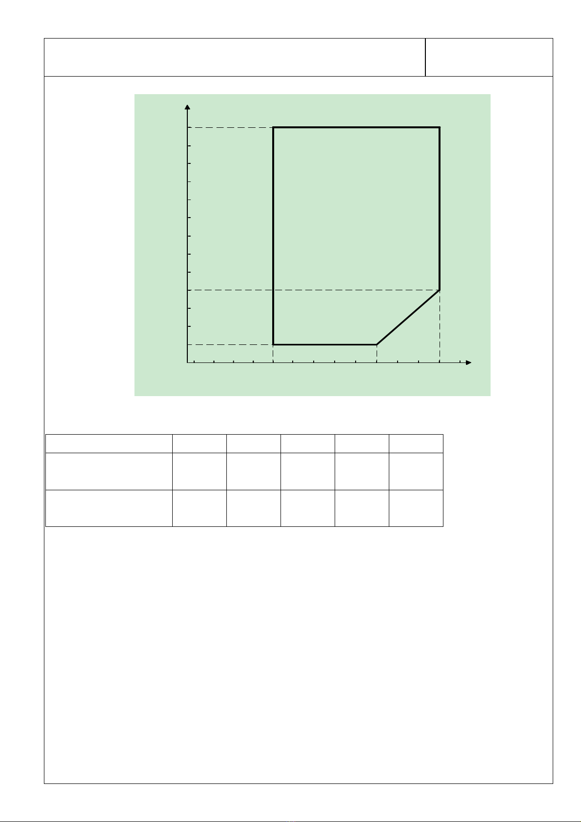
Temperatures and Pressures
The operating temperatures and pressures of the compressor should be within
the range shown in the table 2 and graph 1.
1.3 Operating and Shut-off Period
The compressor should be operated continuously at least for 5 minutes after
being turned ON.
3 minutes shut-off time should be ensured at least until restarting.
1.4 Oil Back and height of the oil level
Oil should be returned continuously to the compressor and not kept in the
refrigeration system.
Oil level of compressor should be higher than 7.5 mm from the lubricating piece
fixed on the end of the crankshaft.
Compressor must not be started operated under a dual-layer separate status.
However, in case of foaming situation, the height of this foam does not mean
the height of the oil level.
If you do not keep the oil level, the oil shortage will occur, and influence the
reliability of compressor.
(Please check the oil level in the compressor with the sight glass we supply.)

HEAT PUMP WATER HEATER COMPRESSOR CRITERIA FOR LONG LIFE SYSTEM
PAGE:6/23
Refrigerating machine oil should be continuing to return to the compressor, but can not remain in the refrigeration system.
A compressor oil should be higher than the height of 7.5mm above the fuel supply port. Compressor operation, not to
allow the two layers were separated oil and refrigerant. However, when the foam state, becomes liquid foam, which is
not part of the oil level.
If you can not meet the oil level will result in supply shortage sliding portion, seriously affecting reliability.
(Available to observe the oil used in the compressor with a sight glass for confirmation)
There should be superheated gas returned to the compressor under all normal operating conditions.
Table 2
Item Operating Envelope
Discharge pressure
MPa{kgf/cm2G}
2.59 {25.39} MAX
(condensing temperature : 70℃)
Suction Pressure
MPa{kgf/cm2G}
0.29~0.95 {1.94~8.67}
(Evaporation Temperature :-15℃~25℃)
(see graph 1)
Compressor case bottom temp
99℃or below and 6 degrees higher than condensing temperature
Motor winding temp. Voltage±10% 127℃MAX
Motor winding temp.
under locked-rotor
condition
under stable condition:
OLR
Average OFF
165℃MAX Temp Highest
Highest
190℃ MAX Average
OLR ON
time
Accumulator temp Higher than outlet pipe of evaporator

HEAT PUMP WATER HEATER COMPRESSOR CRITERIA FOR LONG LIFE SYSTEM
PAGE:7/23
-35 -30 -25 -20 -15 -10 -5 0 5 10 15 20 25 30
Evaporating temperature(℃)
Condensening Temperature(℃)
5 10 15 20 25 30 35 40 45 50 55 60 65 70 75
P1
P2
P3
P4
P5
Graph 1 图 1
P1 P2 P3 P4 P5
Condensing temperature 70℃25℃10℃10℃70℃
Evaporation Temperature 25℃25℃10℃-15℃-15℃
1.5 Discharge pipe temperature
Discharge pipe temperature is measured at a distance 300mm from the surface of compressor
and should be less than 110℃. The tip of the thermocouple is fixed by soldering when
measuring discharge pipe temperature .Furthermore, soldering point is covered with urethane
foam to prevent the effect of wind.

HEAT PUMP WATER HEATER COMPRESSOR CRITERIA FOR LONG LIFE SYSTEM
PAGE:8/23
1.6 Temperature of Shell Bottom
The Temperature of compressor shell Bottom must be 6 degrees higher than the corresponding saturated
temperature of discharge pressure under normal operating conditions.
1.7 Avoid refrigerant migration
The refrigerant migration to compressor shell should be avoided during the heat pump water heater system shut
down periods, It’s suggested that the electric heating belt should be used around
the shell bottom when necessary.
1.8Allowable Incline
The allowable incline should be less than 5°
during operation.
1.9 Pipe Vibration
The displacement of the pipes, which connect from the compressor to otherParts of the refrigerator systems, should be less than
0.8mm(1/32”)when the compressor is operating at rated frequency+10Hz/ -10Hz and voltage range of rated ±10%.
Displacement in excess of 0.8mm(1/32”) will require changing tubelength and/or routing.
径。
1.10 Connecting Tube Design
In designing and routing tubing that connect from the compressor to the
other parts of the air conditioner, following should be considered.
Moving tubes to the moving parts; minimum clearance 12.7mm(1/2”)
Moving tubes to non-moving parts; minimum clearance 9.5mm(3/8”)
Moving tubes never touch to lead wire.
2. PROCESS LIMITATIONS
2.1 The degree of vacuum in the refrigerating system should be lessthan 20Pa
{150×10-3mmHg}at room temperature just before charging refrigerant.
The quantity ofwater should be less than 0.2ml..

HEAT PUMP WATER HEATER COMPRESSOR CRITERIA FOR LONG LIFE SYSTEM
PAGE:9/23
2.2 Prevent moisture from entering into the enclosed unit system . When the moisture
entered into the unit, the refrigerant oil and the organic
compound material presented in the hermetic motor will possibly decompose on the
affecting of water . It will result in the capillary depositing and the reducing
of insulation resistance.
It is necessary to install a dryer to dehumidify the residual moisture mixed
in
the refrigerant in the cycling system . The specially defined device for drying and
filtering of R-290 is advised.
2.3 The weight of foreign particles on the inside surface of the heat
exchanger tubes should be less than 0.05g/m2.
Metallic dust should not be permitted to enter the refrigerating system.
This value means the weight of foreign particles filtered after washing
inside surface of the heat exchanger tubes with R-11.
Prevent the impurities from entering into the enclosed unit system . When the impurities entered into
the enclosed system , it will damage the moving mechanism parts and result in the capillary
depositing.
2.4 Eliminate all system contaminants such as trichlorethylene, alkalies,soap ,acid ,oil & washing fluid used at machining the heat
exchanger tubes.
2.5 Purge parts with drynitrogen ordry air to remove remains in parts
(dust,detergent,etc.) before assembly of system.. Time for purging :over one
second for pipe ;over three seconds for heat exchanger . Purging pressure:
0.9±0.1MPaG.Dew point of dry air: Below-20°C.

HEAT PUMP WATER HEATER COMPRESSOR CRITERIA FOR LONG LIFE SYSTEM
PAGE:10/23
Dry nitrogen shouldbe charged in compressor beforeassembly of system.
Welding should be finished within one minute after charge of nitrogen. Dry nitrogen
needs to be charged again and weld if over one minute. Always purge the compressor with
dry nitrogen during assembly of system .
2.6 The motor winding temperatures should be less than 149℃in process of manufacturing the
refrigerating system. The temperature of the hermetic terminal body should be less than 177℃.
2.7 The compressor should be operated for more than 20 seconds within 15 minutes after charging
refrigerant into the system so proper lubrication results.
2.8 The manufacturing process of refrigerating system must comply with the regulations related to flammable refrigerants, since
R290 is flammable refrigerant.
2.9 Explosion-proof unit should be used in the system.
2.10 Refrigerant R-290 99.9% in purity should be used for apparatus. 99.95% isrecommended, if possible.
3. MISCELLANY
3.1 The pipe and hermetic pins attached to the compressor should not be bent.
3.2 The compressor should never be operated while under vacuum;otherwise,
internal arcing can cause damaging parts.
3.3 The compressor should not be operated to form a vacuum and to absorb air.
3.4 The compressor should not be left opened in the atmosphere for more than
5minutes.
When the air entered into the unit system , it will expedite the deterioration
of the oil and result in the capillary depositing and the reducing of insulation resistance.

HEAT PUMP WATER HEATER COMPRESSOR CRITERIA FOR LONG LIFE SYSTEM
PAGE:11/23
3.5 The electric pulse should not be applied to the hermetic terminals when
thecompressorisundervacuum.
3.6 The compressor should be kept in the clean place with low-moisture.
3.7 The compressor must not be applied for transportation equipment, such as
automobiles, trains, ships, and others.
3.8 The compressor should not be splashed with water intentionally.
3.9 Use the refrigerant of specified brand . When the refrigerant not specified used , it will
possibly cause trouble of theperformance and reliability of the compressor by the impurities
in the refrigerant.
3.10 Refrigerant should be charged from the end of condenser of refrigerating systems. Never
charge refrigerant to the compressor directly.
3.11 Compressor mounting
Rubber grommets are designed soft to provide the noise isolation and to lessen vibration
energy transmission.Stud bolt should be designed to provide sufficient clearance for noise
and vibration isolation and toprevent compressor from coming off its mount.
3.12 The first starting voltage supplied to the refrigerating system should be more than the starting
voltage mentioned TABLE 1(page 3).
The refrigerant can not dissolve inthe oil at the beginning because of the highviscidity ofthe oil.

HEAT PUMP WATER HEATER COMPRESSOR CRITERIA FOR LONG LIFE SYSTEM
PAGE:12/23
3.13 The compressor should be kept out of the corrosive atmosphere such as in a chemicals storage, beside
a hot spring and so on.
3.14 The lead wires should be connected to hermetic terminals without being touched on the surface of the
compressor.
3.15 The fuse or/and breaker should be equipped in the main circuit.
3.16 The oil should be returned continuously to the compressor and not stayed
in the refrigerating system.
3.17 There should be adequate clearance between the OD26-under-surface of
Bolt -Head and the upper surface of rubber grommets.
3.18 To avoid water and impurity into the refrigeration systemand make sure no leakage of
refrigerant during the operating course. It’s required to direct the erector and maintenance
man ofheat pump water heater.

Check upon Delivery
PAGE:13/23
1. Basis for Checking upon Delivery
The Performance test will be carried out in accordance with this “compressor
specification”.
The Safety Performance in accordance with GB4706.1 Safety of household and
similar electrical appliances General requirements and GB 4706.17 Safety
of household and similar electrical appliances Particular requirements for
motor-compressor.
2. Rule for Checking upon Delivery
If come across any quality problem, please notify the company in written form
within 30 days after the arrival of the cargo, the company shall exchange
exactly the number of the products, otherwise they shall be regarded as being
up to standard.

14/23

15/23

16/23

17/23

18/23
Table of contents
Other Ries Air Compressor manuals
Popular Air Compressor manuals by other brands

Speedaire
Speedaire 48UY04 Operating instructions & parts manual

Corken
Corken F291 Installation, operation & maintenance manual

Vixen Air
Vixen Air VXO4850DCF installation guide

Quincy Compressor
Quincy Compressor QED 650 Instruction and maintenance manual

Craftsman
Craftsman 919.167260 owner's manual

EINHELL
EINHELL TC-AC 190/6/8 OF Original operating instructions

Fubag
Fubag BRICO manual

Ingersoll-Rand
Ingersoll-Rand SS3L3 Owner's manual and parts list

ABAC
ABAC A39B/150 CM3 Instructions for use manual

PurePower
PurePower PPAC208 Operator's manual

EINHELL
EINHELL Euro 8/24 operating instructions

Zgonc
Zgonc Yellow Profi Line YPL 500 Translation from the original instruction manual