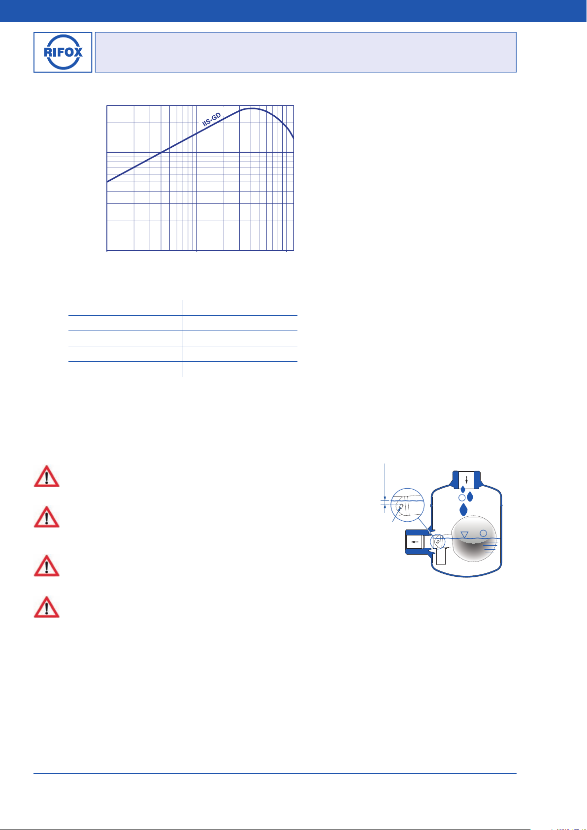
Rifox 1064-N User manual

Model: 1064-N / 1068-N
RIFOmat Float - Controlled Condensate Trap, PN 16
1 Safety instructions
1.1 Proper use
Any improper use, intervention in the design and deviation from the design data automatically lead to termination of the
warranty.
The float-controlled condensate trap 1064-N / 1068-N is designed for the discharge of condensate from pipeline or plant.
Any other usage is not permitted. The manufacturer is not liable for damage resulting from any other usage. The user or
operator bears the risk in this case. This also applies analogously to incorrect assembly, start-up, use and maintenance.
1.2 Warnings and symbols
■Personal risk due to escaping operating medium because of pressure, temperature and weight. Failure to comply with
these warnings results in the risk of accidents.
■Follow the instructions in this operating manual.
■The operator must ensure that this operating manual and, if necessary, other relevant documents are available on site.
■Only trained or instructed personnel may be assigned to handling this equipment.
■Any mode of operation that may impair safety must be avoided.
2 General description and application
2.1 Design of the condensate trap
2.2 Operation limits (see marks on outlet and on housing)
max. operating pressure (bar g) 16
max. operating temperature (°C) 100
2.3 Function limit of control unit: 12 bar g
Picture 1: 1064-N Picture 2: 1068-N
Operating Manual
Breite: 170
Höhe:8,15
Oben Links
278,5 20
RIFOX - Hans Richter GmbH Spezialarmaturen Fon: +49 (0) 421 499 75 - 0 Internet: www.rifox.de
05/2020 -Di. Subject to modifications
Page 1 of 6

10
100
0,1 1 10
Flow rate in kg/h
Pressure difference in bar (with reference to atmospheric pressure)
Performance:
300
5
200
12
2.4 Discharge capacity
Picture 3
For very low pressures:
Pressure difference in bar g Discharge capacity in kg/h
0,02 23
0,04 32
0,06 40
0,08 46
2.5 Function
■ Due to the gravity the condensate flows downwards to the lowest point, which is the condensate trap housing. In the
lowest position of the float the outlet cross-section is close. Rising of the liquid level lifts the float and opens the outlet.
Condensate will be discharged through the upturned immersion tube. Decreasing condensate level closes the outlet again.
2.6 Submerged gastight control unit (Picture 4)
■ The condensate trap must be filled with water before start-up. The required water
trap is automatically adjusted during the proper operation. (Picture 4, Point ①) The
water seal is shown as dimension X in Picture 4.
■ The permanent presence of the minimum condensate level in the condensate trap
is a prerequisite for the complete gas tightness. When the condensate level sinks
under the cross-section (water seal does not exist), the gas tightness is no longer
guaranteed.
■ To ensure permanent gas tightness, it is required that condensate always drops in
the condensate trap. (Picture 4, Point ②) If there are for hours or days no condensate,
gas may leak through the closed valve.
■ The pressure peaks are absorbed by the condensate trap.
When using submerged-gastight control units, please note:
The valve orifice is always under an condensate surface.
If the gas is mixed or dissolved with the condensate, there can be no separation inside the steam trap.
Small amounts of gas can separate from the condensate at the outlet.
In these cases a degassing line at the outlet towards uncritical areas (via the roof for example) may be recommended.
A horizontal inflow can calm the condensate flow and support the self-degassing to separate the gas from the condensate.
When using an angular version (EF) condensate enters from above and can also bring gas into the housing.
With an inlet from below, the degassing happen before the trap, the automatic degassing is most effective.
Traps with submerged-gastight control units should not be used at above 90°C or its use should be clarified with RIFOX in
advance.
1
Min.
2
X: Water Seal
Cross Section
Picture 4
Tabel 1
Operating Manual
Breite: 170
Höhe:8,15
Oben Links
278,5 20
RIFOX - Hans Richter GmbH Spezialarmaturen Fon: +49 (0) 421 499 75 - 0 Internet: www.rifox.de
05/2020
Page 2 of 6
-Di. Subject to modifications

3 Assembly
■ Installation to the lowest point of the pipeline system or plant (see Section 7)
■ Installation positions according to Section 6.
■ The flow direction is shown by the arrow.
■ Remove the protection caps on inlet and outlet.
■ For installation and maintenance it is recommended that the check valve should be installed in the upstream, possibly also
in the downstream.
4 Observation and control
■ The function failure of the condensate trap can be observed as gas leakage, which can be visually monitored by connecting
the outlet of condensate trap into a tank filled with condensate (see section 7).
5 Maintenance and inspection
■ The condensate traps 1064-N and 1068-N are compact welded and can not be disassembled.
■ We recommend to clean and maintain on intervall.
5.1 Clean the condensate trap
■ In the course of time, dirt can accumulate in the housing. It may block the tube and must be removed.
■ Model 1064-N (Picture 1): Dismantle the comdensate trap from the pipeline and fill it with water, so that the dirt is
released. Empty the condensate trap from the inlet. Repeat these processes until the dirt is removed from the housing.
■ Model 1068-N (Picture 2): Screw off the drain plug, flush the condensate trap e.g. according to Picture 5. (Model 1068-N
must not be dismanteld from the pipeline.)
5.2 Function control
■ Turn the condensate traps (1064-N and 1068-N) upside down and back again, the float must strike independently audible
to the housing wall. If necessary please consult Rifox.
5.3 Spare parts
■ The condensate trap are compact welded. It is not possible to change the intern parts. For Model 1068-N (Picture 2) how-
ever, it is possible to change the drain plug and its gasket if required.
Picture 5
Water
1068-N
Dirt
Operating Manual
Breite: 170
Höhe:8,15
Oben Links
278,5 20
RIFOX - Hans Richter GmbH Spezialarmaturen Fon: +49 (0) 421 499 75 - 0 Internet: www.rifox.de
05/2020 -Di. Subject to modifications
Page 3 of 6

6 Installation examples of condensate traps
The condensate trap 1064-N or 1068-N can be installed e.g. as shown below.
7 Monitoring and ensuring the proper operation
7.1 Monitoring the gas leakage
Upon the occurrence of gas leakage because the water seal does not exist: The immersion depth of the tube (geodesic
height) can not be greater than the operating pressure. See Picture 7.
See also Section 7.3.
Picture 7
1064-N
1068-N
Condensate
P1
HImmersion
Gas +
Condensate
Picture 6
Example:
P1= 20 mbar,
In order to “show“ the gas leckage, the immersion depth
of the tube (HImmersion) must be smaller than 0,2 m.
Because 10 m water column ≈1 bar
Ensure to discharge the condensate through an overflow
from the tank. If HImmersion is increased by the increasing
condensate level, it leads to Section 7.2.
Operating Manual
Breite: 170
Höhe:8,15
Oben Links
278,5 20
RIFOX - Hans Richter GmbH Spezialarmaturen Fon: +49 (0) 421 499 75 - 0 Internet: www.rifox.de
05/2020
Page 4 of 6
-Di. Subject to modifications

7.2 Blocking the gas leckage
Upon the occurrence of gas leakage because the water seal does not exist: The immersion depth of the tube (geodesic
height) must be greater than the operating pressure. See Picture 8.
See also Section 7.3.
Condensate
1064-N
1068-N
P1
HImmersion
Gas +
Condensate
Picture 8
7.3 Discharging the gas leakage
If gas leakage occurs, it can be discharged „via the roof“, as shown in Picture 9.
Condensate
Condensate
Gas leakage
„via the roof“
1064-N
1068-N
Gas +
Condensate
Picture 9
Example:
P1= 20 mbar,
In order to block the gas leckage, the immersion depth of
the tube (HImmersion) must be greater than 0,2 m.
Because 10 m water column ≈1 bar
Operating Manual
Breite: 170
Höhe:8,15
Oben Links
278,5 20
RIFOX - Hans Richter GmbH Spezialarmaturen Fon: +49 (0) 421 499 75 - 0 Internet: www.rifox.de
05/2020 -Di. Subject to modifications
Page 5 of 6

7.4 Discharging the condensate from system with vacuum (Picture 10)
■ Downstream siphon prevents the suction of air from the atmosphere (HSiphon).
■ The installation depth (HInstall) enables the increase of the condensate column, which overcomes the vacuum.
■ The geodesic height (HGeod) and siphon height (HSiphon) are equal (HGeod = HSiphon). They depend on the vacuum value and
the required flow rate (quantity of condensate).
■ Per meter the pressure increases 0.1 bar because of the geodesic height (HGeod).
X
Condensate
Siphon
Air
HInstall
HGeod
HSiphon
Condensate
column
Condensate
1064-N
1068-N
Gas + Con-
densate
System with
Vacuum
Picture 10
8 Conformity assessment
The pressure equipment is in accordance with the Pressure Vessel Directive 2014/68/EU, Article 4, subsection 3 and there-
fore bears no CE mark. A detailed declaration of conformity assessment according to PED is available as separate document.
Please request if necessary, if not attached.
Operating Manual
Breite: 170
Höhe:8,15
Oben Links
278,5 20
RIFOX - Hans Richter GmbH Spezialarmaturen Fon: +49 (0) 421 499 75 - 0 Internet: www.rifox.de
05/2020
Page 6 of 6
-Di. Subject to modifications
This manual suits for next models
1
Table of contents
Other Rifox Heat Pump manuals
Popular Heat Pump manuals by other brands

CANVAC
CANVAC Q Heat S Series instruction manual

Ideal Heating
Ideal Heating ECOMOD AHP60 26 kW Installation and servicing

Daikin
Daikin EHYHBH05AA installation manual

ALLIANCE
ALLIANCE ALLPH 91Kw Installation & operation manual

York
York SUNLINE 2000 48 Technical guide

Thermia
Thermia Diplomat Inverter Commissioning

Daikin
Daikin Altherma 3 R F Installer's reference guide

Mitsubishi Electric
Mitsubishi Electric PUZ-WM AA Series installation manual

Samsung
Samsung AE040RXED Series installation manual

Rheem
Rheem RTHP009 Installation maintenance and service manual

LG
LG HM031M Engineering product data book

Danfoss
Danfoss DHP-H Installation and service instructions