Riken Keiki AC-3 User manual

PT5E-0403
RIKEN PHOTOELECTRON
SPECTROMETER
AC-3
INSTRUCTION MANUAL

1
1.In the beginning
…………………………2
1-1.Operational purpose …………………………2
1-2.Caution for the safety …………………………3
1-3.Method of confirmation for CE marking type …………………………3
2.Precautions on operation
…………………………4
2-1.Danger items …………………………4
2-2.Warning items …………………………5
2-3.Caution items …………………………7
3.Product functions
…………………………
8
3-1.Designations …………………………
8
3-2.Name of each part and functions ………………………
13
3-3.Block diagram for nitrogen gas tubing ………………………15
4.Installation
………………………18
4-1.Cautions for transportation and installation ………………………18
4-2.Cable connection ………………………18
4-3.Compressed air tubing ………………………19
4-4.Nitrogen gas tubing ………………………19
5.Operation method
………………………20
5-1.Check items ………………………20
5-2.Connection of power source ………………………20
5-3.Power on ………………………21
5-4.Measurement ………………………21
5-5.Readout the width of slit ………………………22
5-6.Stopping the operation ………………………23
6.Maintenance check
………………………24
6-1.Daily check ………………………24
6-2.Consumable parts ………………………26
7.Measure at abnormal case
………………………27
7-1.Self-diagnosis at trouble ………………………27
7-2.Responding to the trouble ………………………27
7-3.Before it is thought to be a trouble ………………………28
8.Definition of terms
………………………29
9.Measurement principle
………………………30
9-1.Measurement principle of photo-election ………………………30
9-2.Measurement of photo-election work function ………………………31
10.List of product specification
………………………32
10-1.Product specifications ………………………32
10-2.Composition list ………………………34
TABLE OF CONTENTS

2
1. In the Beginning
It would be of our great pleasure to buy our PHOTOELECTRON SPECTROMETER “AC-3” this time.
And it is requested to check by referring model number and this instruction manual.
The required items to do this operation correctly are described in this instruction manual. Then, read
this manual fully even for well experienced customers who operated past as well as
1
st
time reader
and customers, and your understanding of this matter would be much appreciated.
Then, it is kindly arranged that this INSTRUCTION MANUAL must be ready to reach to and is stored in
easy place to get by end users it if required.
This manual is composed of followings. Read them to your necessity.
Title Contents
AC-3 INSTRUCTION MANUAL This is a instruction manual of AC-3. Operational
procedures of AC-3 hardware are described.
AC-3 for Windows INSTRUCTION MANUAL
(Measurement of work function and ionization
potential)
Operation manual for Windows software.
Measurement procedures for work function and ionization
potential are described.
AC-3 Consumable parts replacement method Replacement method for consumable parts is described.
※It is strictly prohibited to copy on transcribe a part on whole of this manual without our prior
approval.
1-1. Operational purpose
・
This is designed to measure the photoelectron emission in air under normal temperature and normal
pressure of solid state sample surface in the room of clean laboratory or fine instrument factory to
be designed to generate the least emission of contamination on the material surface.
・
The measurement of threshold energy photoelectron emission generated to radiate ultraviolet rays.
(In most case, this threshold energy is interpreted as work function and ionization potential.)

3
1-2. Caution for the safety
The following headlines are used in this manual to work safety and effectively.
DANGER indicates an imminently hazardous situation which, if not avoided, will result in death or
serious injury or serious damage to the product. This signal word is to be limited to the most extreme
situation.
WARNING indicates a potentially hazardous situation which, if not avoided, could result in death or
serious injury on the human body or object.
CAUTION indicates a potentially hazardous situation which, if not avoided, may result in minor or
moderate injury or some damage on the human body or object. It may also be used to alert against
unsafe practices.
This means “ADVICE” at operation
1-3. Method of confirmation for CE marking type
The CE marking is labeled on the detector in case of comply with CE marking. Please confirm the
instrument specification before using. Please refer Declaration of Conformity that is at the end of this
manual if you have CE marking type.
You can confirm instrument specification to see the CE marking as follows.
DANGER
WARNING
CAUTION
*
N
OTE
CE marking
CE marking label

4
2-1.Danger item
DANGER
・Do not install this instrument in a closed confined room. There is a danger to occure accident
caused by oxygen deficiency if nitrogen gas would leak, since this instrument uses nitrogen gas
on operation. Be sure to install the oxygen deficiency alarm in the operation room.
・Do not use this instrument without flowing nitrogen gas. If nitrogen gas is not flowed, it is
danger that the ozone gas may be generated.
2. Precautions on operation

5
2-2.Warning items
WARNING
・Do not open the cover while in operation.
・There is the high voltage part inside, you may receive the electric shock.
・As the ultraviolet rays are radiated from the lit-on lamp, do not see it by naked eyes
absolutely. This may cause the pain of eye or difficulties of eyesight.
・Do not illuminate ultraviolet rays directly to the skin. This may cause the inflammation of skin
・As the lamp lit on or just after light-on is heated up, do not touch it by hand or skin. It may
cause a burn.
・Abnormal heat, fume, abnormal sound and nasty smell.
If any abnormality should take place during operation, stop operation immediately, switch off
the power and remove cable from the power socket. If continue to use, it may cause the
electric shock and fire.
・Shock caused by transportation, dropping, impact and so on.
Do not give a shock more than 1G by transportation on movement, dropping, impact and so
on.
・As this is composed of fine electronics parts, it may become far from normal operation and
measurement.
・Operation at place with high temperature, humidity and plenty of dust
・Do not store or operate at high temperature, humidity and plenty of dust. It may cause trouble
action., electric shock and fire. The operation shall be made at the given range of temperature
and humidity.
・When desired to move from low temperature place to high temperature place, there is the case
of dew inside or on the surface. The operation in such may cause the trouble. When move the
product, leave it for some hours alone at the operation place and let it used to the ambient
temperature.
・When use the deteriorated parts
・Check the pipeline and replace the appropriate parts regularly. When continue to use the
deteriorated parts, it may cause breakage of pipe and exploded accident.
・The lamp which passes away life excessively may cause explosion.

6
WARNING
・Operation power
Do not use other power voltage than the described. It may cause the breakage of product,
electric shock and fire.
・Connection of earth terminal (grounding)
For safety, connect the power cable to electric outlet with earth (3P). When you use the
accessory transducer plug, ground the earth terminal. If not grounded, it may cause the
electric shock.
・Handling of power cable
・Do not put things on the power cable, pull in, push out, bend or slice. As power cable is
damaged, it may cause electric shock and fire.
・When plug in and out the power cable into electric outlet, be sure to do it with power plug
grasped. When pull the cable, a part may be disconnected and cause the fire.
・Check that there is no dust on the power plug and plug into electric outlet fully. Then do not
use the loose electric outlet which may cause the contact failure. It may cause fire.
・When plug in the power cable, do not touch it by wet hand. It may cause the electric shock.
・Do not connect many cables into the same electric outlet. This may cause the fire and it may
affect other product by power shutoff of breaker due to over use of power. This is subject
to commercial power electric noise and may easily cause the trouble.
・Intrusion of foreign substance
Do not put other material than the measuring goods from the sample door. Also, do not enter
the metal material or flammable material inside from the windows. When use as it is, it may
cause the faulty action, electric shock and fire.
・Put things onto the product
Do not pull small metal goods such as pin, clip and container with water such as vane, plant.
When they put inside and operate it as it is, it may cause the damage of products, the electric
shock and fire.

7
2-3. Caution items
CAUTION
・
Contact to the end surface of metal
When required to contact the end surface such as iron plate, enough attention and care
should be taken so that any damage cannot take place.
・
Do not use the Walky-talky near the product
When use the walky-talky etc which emits electric wave near the cable or product, there is
the case that the correct measurement cannot be carried out and the attention for
it would be required. When use such walky-talky etc, use it where there is no influence.
・
Procedure of power on
Make power on after Operating System (OS) for Personal Computer is set up. If the power
gets on before Operating System is set up, it may cause the error of operation.
・
Power on again
When make power on again, wait more than 5 minutes after power off. When make power on
within 5 minutes, there is the case that the normal operation cannot be carried out.
・ Operation at the unstable place
Do not put it at the suitable place such as slant and vibrating place. It may not do the normal
operation.
・
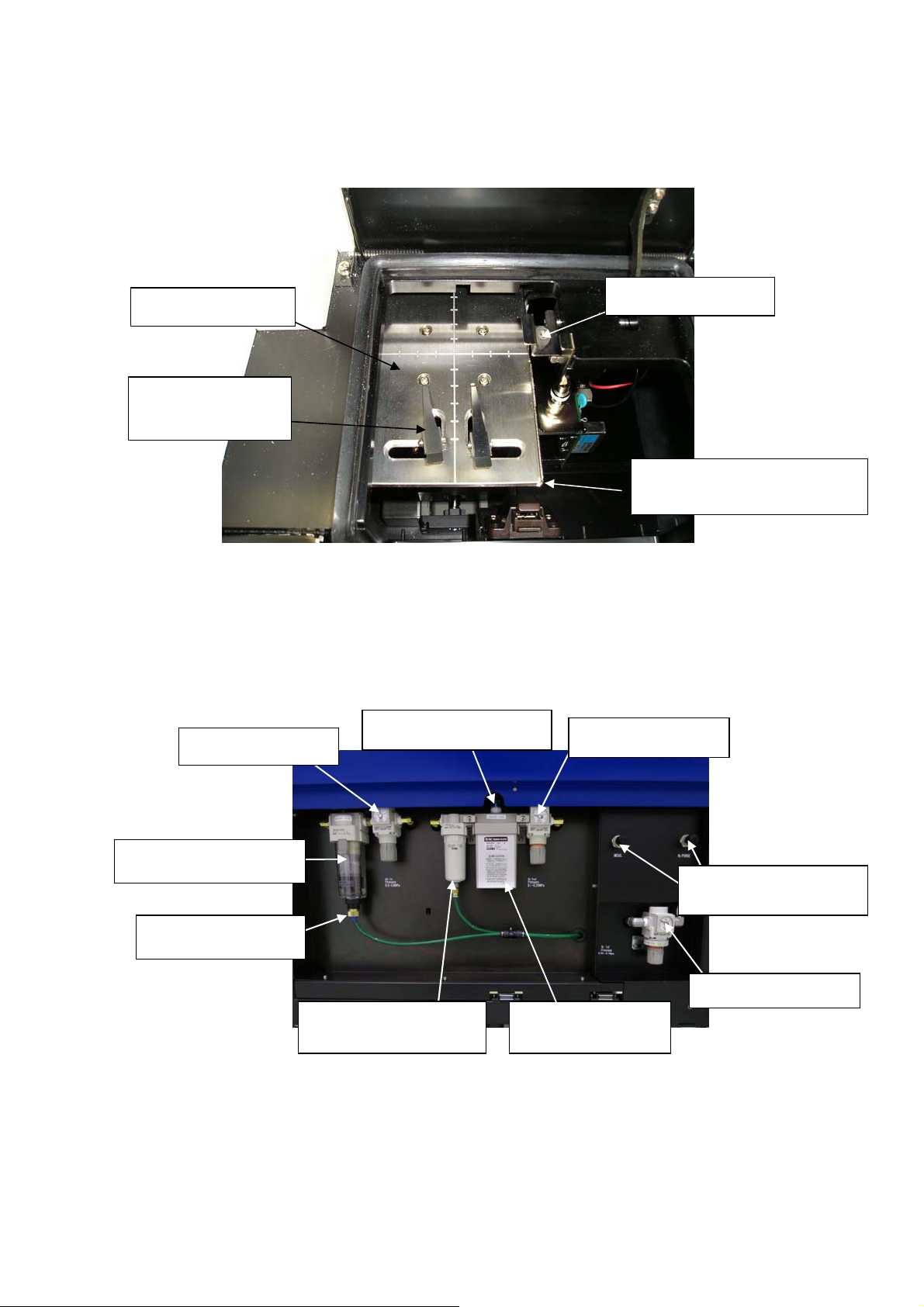
The caution for compressed air
When the following material is contained in the compressed air, it may deteriorate the
detector and dry air generating conditioner and there is possibility for damage.
Kind Materials which should not contain
Solvent
Acetone, Benzene, Phenol, Toluene, Trichloroethylene, Xylene, Cresol,
Thinner, Aniline, Chloroform, Alcohol, Dioxane, Tetrahydrofuran, Methylene
chloride, Cyclohexanone, Carbon tetrachloride etc
Acid Sulfuric acid, Nitric acid, Hydrochloric acid, Acetic acid, Lactic acid,
Chromic acid etc
Gas Chlorine, Sulfur dioxide, Hydrogen sulfide, Bromine, Semiconductor
processing gas etc
Oil Hydraulic fluid (Phosphatic Ester), Fuel oil, Water soluble cutting
fluid(Alkaline), Kerosene etc
・
When use at more than given pressure, it may damage the dry air generating system.
・
When induct liquid such as water from the compressed air pipe, it may damage the system.
・ When induct other gas such as N2 gas, oxygen, inert gas than air from compressed air pipe,
it may damage the system.

8
3-1.Designations
3-1-1.Front panel
3-1-2. Sliding door inside
(10) Flow meter for nitrogen gas
(9) Change over handle for
nitrogen gas flow
(8) Sample door
(6) Sliding door
(7) Maintenance door 1
(4) OPEN Light
(2) ERROR A
Light
(3) ERROR B
Light
(1) POWER/STANDBY Light
functions
(5) Power switch
3. Product functions

9
3-1-3.Sample door Inside
3-1-4.Maintenance door 1 Inside
(11) Sample stage
(12) Sample clip
(13) Height gauge
(14) Height adjusting
(16) Pressure gauge
(16) Pressure gauge
(17) Dew point checker
(19) Drain cock
(20) Micro-mist
separator
(18) Mist separator
(16) Pressure
g
au
g
e
(15) Nitrogen gas flow
adjusting knob
(21) Membrane type
air dryer
(14) Height adjusting lever

10
3-1-5.Rear panel
(22) Maintenance door 3
(26) AC power input
(24) Fuse
(23) RS232C connector
(25) Breaker
(29) Nitrogen gas IN
(30) Nitrogen
gas OUT
and Bypass OUT
(27) Compressed air IN
(28) Drain OUT

11
3-1-6.Upper panel
3-1-7.Maintenance door 2, inside
(31) Maintenance door 2
(33) Entrance slit
(34)
Exit slit
(32) Detector

12
3-1-8.Side panel
3-1-9.Maintenance door 4, inside
(36)
Photoelectron multiplier tube
(35)
Maintenance door 4

13
3-2.Name of each part and function
3-2-1.Front panel
(1) POWER/STANDBY light :At measurement・・・Green light turns on.
At waiting (Warming up)・・・Green light flashes
(2) ERROR “A” light :At initial power on/trouble・・・Red light flashes
(Light off at measuring condition)
(3) ERROR “B” light :At initial power on/trouble・・・Red light flashes.
(Light off at measuring condition)
(4) OPEN light :Orange light flashes when sample door is opened.
(5) Power switch :ON(|)、OFF(○)
(6) Sliding door :Grip the handle and slide to the side to open the door.
(7) Maintenance door 1
3-2-2.Sliding door, inside
(8) Sample door :Push the upper surface to open measuring chamber.
(9) Change-over handle for Nitrogen gas flow :Adjusts the Nitrogen gas flow.
(10) Flow-meter for Nitrogen gas :Checks Nitrogen gas flow
3-2-3.Sample door, inside
(11)Sample stage :Stage to put on the sample
(12)Sample clip :Fixes the sample and makes the sample grounding
(13)Height gauge :This gives height control standard of measuring surface.
(14)Height adjusting lever :Changes the height of measuring surface
3-2-4.Sample door 1, inside
(15)Nitrogen gas flow adjusting knob:To adjust Nitrogen gas flow.
(16)Pressure gauge :Pressure gauge for compressed air.
(17)Dew point checker :Checks dew point
(18)Mist separator :Separates the moisture in gas
(19)Drain cock :Cock to remove the drain
(20)Micro-mist separator :Separates the moisture contained in the gas.
(21)Membrane type air dryer :Removes the humidity contained in the gas.

14
3-2-5.Rear panel
(22)Maintenance door 3 :UV lamp is installed inside this door
(23)RS-232C connector :Port to connect PC
(24)Fuse :3A, 2 pieces
(25)Breaker :This is for the main unit.
(26)AC power input :To input the AC power source
(27)Compressed air IN :Inlet for compressed air
(28)Drain OUT :Drain outlet
(29)Nitrogen gas IN :Inlet for Nitrogen gas
(30)Nitrogen gas OUT and bypass OUT :Outlet for Nitrogen gas
3-2-6.Upper panel
(31)Maintenance door 2
3-2-7.Maintenance door 2, Inside
(32)Detector :Open counter
(33)Entrance slit :To adjust the entrance slit
(34)Exit slit :To adjust the exit slit
3-2-8.Side panel
(35)Maintenance door 4
3-2-9.Maintenance door 4, inside
(36)Photoelectron multifier tube :Detects the photoelectron as electric current.

15
3-3.Block diagram
3-3-1.Electric line
:Electron
:Ultraviolet rays
:Pipe
:Electric signal line
UV
Lamp
Power
source for
UV lamp
Sample
P
h
o
t
o
-
s
e
n
s
o
r
Z stage
X stage
Low energy
electron counter
Controller
X stage driver
Controller
Personal computer
CRT display
Printer
Display/Controller
Dry air
Sam
p
le
e
Detector
Spectro
meter
C
o
n
d
e
n
s
e
d
o
p
t
i
c
a
l
s
y
s
t
e
m
D
i
a
p
h
r
a
g
m
A
t
t
e
n
u
a
t
o
r
Nitrogen IN Nitrogen OUT
AC-3
e

16
3-3-2.Compressed air tubing system
Pressure gauge for primary pressure
0.5~0.6 MPa
Mist separator Regulator
Micro mist
separator
Pressure gauge for secondary pressure
0.1
~
0.25 MPa
Regulator
Detector
Compressed air IN
Pressure:0.5~0.7MPa
Flow:Over 5.5 NL/min
Tubing:6×4 mm
Membrane
air dryer
2 port
solenoid valve
Mass flow controller
At measuring: 0.251 L/min
At purging: 2.01 L/min
Drain out

17
3-3-3.Block diagram for nitrogen gas tubing
Pressure gauge
0.05~0.1 MPa
Pressure:0.5~0.6 MPa
Flow rate : Above 5.0
NL/min
Tubing:6×4 mm
N
2
IN
N
2
OUT
BYPASS
3-way
cock Needle Valve
(PARGE)
Needle Valve (MEAS.)
Regulator
Relief Valve
Spectrometer
Flow meter

18
4-1.Caution for transportation and installation
① When transport, take care not to overload more than 1 G acceleration by vibration.
② Install this product on the floor.
③ Use this products inside of the room such as laboratory etc under stable temperature and
humidity. Especially, the installation to the following place shall be requested to avoid. It may
cause the trouble and accident.
・Place outside of room and with water drops
・Place full of dust and humidity
・Place full of vibration
・Drastic change place of temp and humidity. Direct sun-draught and vibration wind.
・Place full of solvent, acid, alkaline vapors, much chemical floating.
④ As this is composed of fine electronics parts, do not drop or throw and mount it in stable and
horizontal place.
⑤ Keep noise source from large capacity of transducer, motor, motive power and high voltage
generator.
⑥ When use the walky-talky or hand-phone, put it at over 1m away from it to prevent the faulty
operation by electric wave barrier.
4-2.Cable connection
① Connect this product and personal computer by RS cable (9 pin) supplied as accessory.
② Connect power cable to this product.
4
.
Installation

19
4-3.Compressed air tubing
① As tubing material, use the following nylon tube.
AIR IN side: Outer dia φ6mm, Inner dia φ4mm, Press resistance over 0.7MPa.
DRAIN OUT side: Outer dia φ8mm, Inner φ5mm, Press resistance over 0.3MPa.
② Check that the tube is cut vertically, the cross section is circle and there is no damage.
③ Check that the tube plugs into depth surely and cannot be pulled out after mounting .
④ Connect instrumentation air or compressed air (Pressure : 0.5~0.7MPa) to AIR IN side.
⑤ Tubing for drain OUT shall be led to the outside of this unit.
4-4.Nitrogen gas tubing
①
Use the stainless or PTFE tube for the IN side tubing.
Nitrogen gas IN side: Outer dia φ6mm, Inner diaφ4mm, Pressure resistance over 0.7MPa.
Nitrogen gas OUT side: Outer dia φ8mm, Inner dia φ5mm, Pressure resistance over 0.3MPa.
② Check that the tube is cut vertically, the cross section is circle and there is no damage.
③ Check that the tube plugs into depth surely and cannot be pulled out after mounting .
④ Connect Nitrogen gas (above 99.9% purity) to the N
2
IN side.
⑤ Tubing for N
2
OUT and BYPASS OUT shall be discharged to outdoor.
⑥ Adjust the pressure between 0.5-0.6Mpa with adjusting knob of the lower part of gauge by
checking pressure gauge.
⑦ Turn the change-over handle to the MEAS side and adjust the flow rate between 1.9-2.1L/min
with nitrogen gas flow adjusting knob by watching the flowmeter.
⑧ Turn this change-over handle to the PURGE side and adjust the flow rate between 4.9-5.1L/min
with nitrogen gas flow adjusting knob by watching the flowmeter.
CAUTION
Water is discharged from DRAIN OUT. Exhaust to the outside so that the spherical instrument
cannot be wet. At this time, to prevent advertent flow, it is arranged that water can run down.
DANGER
It is very dangerous since this unit uses a N
2
gas in a high enclosed room.
Be sure to ventilate inside room. Also install oxygen detector. Nitrogen gas discharged from N
2
OUT
shall be exhausted to the outdoor.
Table of contents
Popular Laboratory Equipment manuals by other brands

Sigma
Sigma 4-16KS operating manual

Agilent Technologies
Agilent Technologies 6890 Series operating manual

Endress+Hauser
Endress+Hauser Analytik Jena Biometra TRIO operating manual

IKA
IKA ULTRA -TURRAX Tube Drive P control operating instructions

Kodak
Kodak X-Omat 2000 installation instructions

corob
corob FLEX 450 user manual