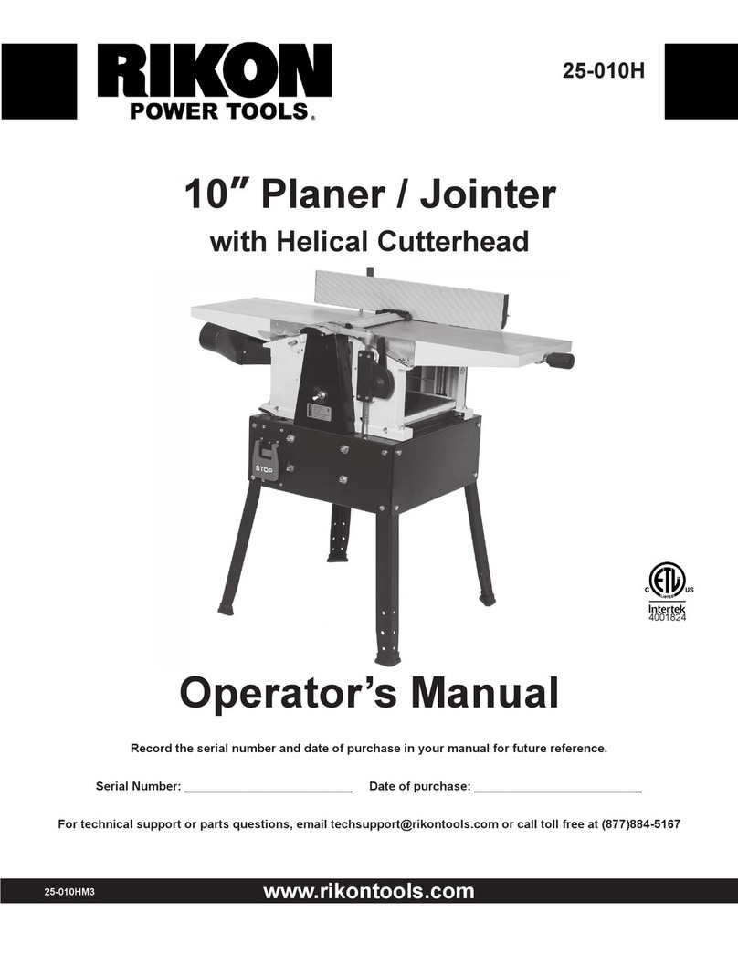
Rikon Power Tools 23-400 User manual

23-400
www.rikontools.com
23-400M2
16” Thickness Planer
Operator’s Manual
Record the serial number and date of purchase in your manual for future reference.
Serial Number: _________________________ Date of purchase: _________________________
For technical support or parts questions, email [email protected] or call toll free at (877)884-5167
4001824

Index
1 GENERAL INFORMATION
1.1 Foreword
2 MACHINE DESCRIPTION
2.1 Machine identification
2.2 Getting to know your machine
2.3 Technical specification
2.4 Recommended protective clothing
2.5 Noise emission
2.6 Prescribed use of the machine
2.7 Hazards
2.8 Safety instructions for planer
3 INSTALLATION
3.1 Lifting and unloading
3.2 Position of the machine
3.3 Identifying shipping boxes
3.4 Installations of loose parts
3.5 Electrical connection
3.6 Dust chute - Installation
4 INSTALLATION AND ADJUSTMENT
4.1. Planer table height adjustment
5 OPERATING PROCEDURES
5.1 ON/OFF switch
5.3 Thicknessing
6 MAINTENANCE
6.1 Replacing cutter knives
6.2 Drive Belt Check
7 DIAGRAMS & COMPONENTS
8 NOTES
9 WARRANTY
2

1. General Information
1.1 FOREWORD
This manual must be read and understood before operating the machine. This will provide a better working knowledge of the
machine, for increased safety and to obtain the best results.
2. Machine Description
2.1 MACHINE IDENTIFICATION
There is a metallic identification plate fixed to the machine, containing the manufacturer's data, year of construction, serial number.
2.2 GETTING TO KNOW YOUR MACHINE
1 Planer table
2 Cutterhead guard
3 Opening handle
4 On/off switch
5 Cover
6 Locking level
7 Height setting of thickness table
8 Adjustment handle for feed speed
9 Dust chute
10 Plug
2
4
6
8
3
5
1
9
10
7
3

2.3 TECHNICAL SPECIFICATION
SPECIFICATION 23-400
Feed speed SF/min 16 to 23
Cutterhead speed rpm 5100
Cutterhead diameter 2-3/4"
Max planer capacity 8-13/16" x 16"
Max depth of cut 1/8"
Knives pcs 3
Motor power input 3HP
Net Weight 375lbs
2.4 RECOMMENDED PROTECTIVE CLOTHING
• Non-slip footwear is recommended.
• Do not wear loose clothing, neckties or jewellery; they can be caught in moving parts.
• Roll up long sleeves above the elbow.
• Wear protective hair covering to contain long hair.
2.5 NOISE EMISSION
The measurements of noise, in the working position and during operation, were carried out under the standard ISO 7960 Annex B and C:
Instantaneous acoustic pressure:
Sound power level(no load) <98dB(A)
Sound power level(load) <107dB(A)
Sound Pressure level(no load) <89dB(A)
Sound Pressure level(load) <98dB(A)
Constant K=4 dB measured in accordance with EN ISO 3746:1995
The figures quoted are emission levels and are not necessarily safe working levels. Whilst there is a correlation between the emission
and exposure levels, this cannot be used reliably to determine whether or not further precautions are required. Factors that influence
the actual level of exposure of the workforce include the characteristics of the work room and the other sources of noise etc. i.e.
the number of machines and other adjacent processes. Also the permissible exposure level can vary from country to country. This
information, however, will enable the user of the machine to make a better evaluation of the hazard and risk.
2.6 PRESCRIBED USE OF THE MACHINE
This machine is intended for surface thickness planing of solid woods. The permissible workpiece dimensions must be observed (see
Technical Specification).
Any other use is not as specified. Unspecified use, modification of the machine or use of parts not tested and approved by the
equipment manufacturer can cause unforeseen damage.
2.7 HAZARDS
ATTENTION Planer still present risks that cannot be eliminated by the manufacturer. Therefore the user must be aware that wood
working machines are dangerous if not used with care and all safety precautions adhered to.
4

2.8 SAFETY INSTRUCTIONS FOR PLANERS
A planer is a tool which can, due to operator carelessness, cause serious personal injury. It is therefore strongly recommended you
read and observe:
· these instructions, particularly the special safety information in the respective chapters;
· the relevant guidelines or regulations for the prevention of accidents pertaining to the use of planers, where applicable.
Keep all documents, supplied with the machine, for future reference.
The planer shall only be started and operated by persons familiar with planers and who are at any time aware of the dangers
associated with the operation of such tool. Persons under 18 years of age shall use this planer only under the supervision of an
instructor in the course of their vocational training.
The following residual risks do principally exist with planers and can not, even by employing safety devices, completely eliminated:
- Hazard generated by environmental conditions:
do not operate the planer in rain or damp environment. Ensure sufficient lighting. Do not
operate the planer near inflammable liquids or gases.
- Hazard to other persons in the work area:
Keep bystanders, particularly children, out of the danger zone.
- Risk of injury by machine faults:
check the planer for damage before any use. Do not operate the machine with a damaged part. Replace blunt cutter knives at once.
Risk of injury by kickback if a blunt knife gets caught in the workpiece's surface.
- Risk of injury by an unstable stand of the planer:
when working long stock use suitable supports on both sides of the machine. Avoid adverse body positions. Ensure firm footing, and
keep your balance at all times.
- Risk of injury by foreign objects in the machine:
prior to any starting of the machine ensure that there are no objects (e.g. tools) in the machine.
- Risk of injury by workpiece kickback (workpiece is caught by the rotating cutterhead and thrown back against the
operator):
operate machine only with a fully functional anti-kickback lock. Always use sharp cutter knives. If in doubt check workpiece for
inclusion of foreign objects (e.g. nails, screws, lose knots).
- Risk of injury by touching the rotating cutterhead:
always keep your hands well clear of the cutterhead. Switch machine off and plug out if it is not used.
- Danger! Drawing-in/trapping hazard!
Take care that no parts of the body or clothing can get caught and drawn in by the rotating cutterhead (do not wear neck ties and
garments with wide sleeves; contain long hair with a hairnet).
- Risk of injury by cuts with cutterhead at standstill: Wear gloves when changing cutter knives.
- Risk of injury by inhaling wood dust: dust of certain timber species (e.g. oak, beech, ash) can cause cancer when inhaled. Use a
suitable dust collector:
- fitting the outer diameter of the suction port (100 mm)
- air volume >= 815 m3/h;
- vacuum at suction port of machine >= 740 Pa;
- air speed at suction port of machine >= 20 m/s;
- Risk of injury by inadequate personal protection: when planing, wear:
- dust respirator;
- hearing protection;
- safety goggles.
5
3. Installation
3.1. LIFTING AND UNLOADING
The machine can be transported by two means:
- with a forklift truck. To do so, the machine is secured on a
pallet with four hex bolts.
- by several persons slide the machine from the pallet.
CAUTION
Do not carry the machine holding it at the infeed and outfeed
tables, these are not designed to withstand the tensile load by
the machine weight.
3.2 POSITION OF THE MACHINE
CAUTION
It is prohibited to install the machine in explosive environments.
Ensure that the floor area around the machine is level, well
maintained and free from loose material such as saw dust or
other wood waste.
1. Remove four mounting bolts from the machine base.
2. Lift machine off the pallet and set down on the floor.
3. Fix the machine to the floor. Fix the machine feet and fix on
ground by means of expansion bolts (not supplied).
3.3 IDENTIFYING SHIPPING BOXES
BEFORE ASSEMBLY
It is advisable that before unpacking to have plenty of paper
towels or cloths available to clean off the rust preservative.
FIG. 1
FIG. 2
3.4. INSTALLATIONS OF LOOSE PARTS
The machine is supplied almost assembled. Prior to use, the
handwheel must be fitted.
Install the handwheel (A, Fig.4) with set screw (B, Fig.4)
FIG. 4
B
A
6

3.6. DUST CHUTE - INSTALLATION
The dust chute complete with suction connector must be
installed before planing.
Connect a suitable dust collector to the suction connector of the
planer.
TH410 Single phase
3.5. WIRING DIAGRAM
In the event of a malfunction or breakdown, grounding provides a path of least resistance for electric current to reduce the risk of elec-
tric shock. This tool is equipped with an electric cord having an equipment-grounding conductor and a grounding plug. The plug must
be plugged into a matching outlet that is properly installed and grounded in accordance with all local codes and ordinances.
Do not modify the plug provided. If it will not t the outlet, have the proper outlet installed by a qualied electrician.
Improper connection of the equipment-grounding conductor can result in a risk of electric shock. The conductor, with insulation having
an outer surface that is green with or without yellow stripes, is the equipment-grounding conductor. If repair or replacement of the
electric cord or plug is necessary, do not connect the equipment-grounding conductor to a live terminal.
Check with a qualied electrician or service personnel if the grounding instructions are not completely understood, or if in doubt as to
whether the tool is properly grounded.
Use only three wire extension cords that have three-prong grounding plugs and three-pole receptacles that accept the tool's plug.
Repair or replace a damaged or worn cord immediately.
7

4. Adjustment
4.1. PLANER TABLE HEIGHT ADJUSTMENT
With the height setting for the planer bed the planing thickness
(= thickness of the workpiece after planing) is set when the
machine is used for thickness planing.
· Per pass a maximum of 1/8" material can be removed.
· Workpieces of max. 8-13/16" thickness can be planed. Height
adjustment is made with a handwheel (A, Fig.10). One full turn
of the handwheel changes the height of the planer bed (B,
Fig.10) by 1/8".
· Clockwise turning = raises the planer bed
· Counter-clockwise turning = lowers the planer bed. The set
planing thickness is indicated on the scale (C, Fig.10).
- When the height is settled, locking the table with locking lever
(D, Fig.10)
B
C
D
FIG. 5
A
5. Operating Procedures
5.1. ON/OFF SWITCH (Fig.13)
· To switch ON = press green switch button.
· To switch OFF = close cover or press red switch button.
· To unlock the switch cover push the pin on the stop cover.
FIG. 6
5.2. THICKNESSING
Note: Thickness planing is used to reduce a workpiece with one
already surface planed surface to a desired thickness.
- The workpiece is run through the planer.
- The surface already planed flat rests on the planer bed.
- The workpiece is cut on the upper side.
Workpiece dimensions
- Length: min. 8-13/16"; for workpieces over 72" use a second
person for support or auxillary rollers.
- Width: max. 16".
- Thickness: min 1/4"; max. 8-13/16".
Note: The max. depth of cut for a single pass is 1/8".
1. Assume proper operating position:
- to feed the workpiece into the machine, position yourself offset
to one side of the feed opening.
FIG. 7
8

- to remove the workpiece from the machine, position yourself
offset to one side of the outfeed opening.
2. To thickness plane stock which surfaces are not parallel, use
suitable feeding aids (make tting templates).
3. Set planing thickness.
4. Start motor.
5. Feed workpiece slowly and straight into the planer. It will then
be automatically fed through the planer.
6. Guide workpiece straight through the planer.
7. Switch machine off if no further cutting is to be done immedi-
ately afterwards.
5.3. FEED SPEED CHANGE
The feed speed of this machine can be adjusted by the handle (A,
Fig.9).
- Start the motor
- Turn the handle clockwise, the feed speed will be increased.
- Turn the handle counter-clockwise, the feed speed will de-
crease.
Note: The feed speed changing handle only can be operated
when the motor is running.
A
FIG. 8
FIG. 9
9

6.1 REPLACING CUTTER KNIVES
CAUTION! Risk of personal injury by cuts from the cutter knives!
Wear gloves when changing cutter knives.
To remove the cutter knives:
1. Unplug power cable.
2. Open the cutterhead cover.
3. Turn the ve hexagon head screws of the cutter knife lockbar
(Fig.10).
4. First remove cutter knife, then cutter knife lockbar from the
cutterhead.
5. Clean all surfaces of the cutterhead and cutter knife lockbar
with a suitable solvent.
6. Place new cutter knife on cutter knife lockbar.
7. Place cutter knife lockbar with the installed cutter knife into the
cutterhead.
8. Check the projection of the knives:
- With the provided straight edge gauge .
- Place straight edge gauge across outfeed table and cutterhead
as shown.
- Turn cutterhead by hand one turn against the direction of feed.
- The cutter knives are set correctly if the straight edge is moved
forward 1/8" to 1/4" by the turning cutterhead. This check must be
performed at both ends of the cutterhead. (Fig.11)
9. To tighten the cutter knives, turn the ve hexagon head screws
of the cutter knife lockbar fully out. To prevent distortion of the cut-
ter knife lockbar start with the screws in the center, then tighten
the screws closer to the edges step by step.(Fig.12)
Danger!
- Do not extend tool when tightening the screws.
- Do not tighten bolts by striking the wrench.
10. Return cutterhead cover to its closed position.
6. Maintenance
4 - 6 mm
FIG. 10
FIG. 11
FIG. 12
10

6.2 Drive Belt Check
The cutterhead drive belt and the feedgear drive belt need to
be checked periodically and retightened if necessary. Both drive
belts are located behind the machine's side panel.
Checking the drive belt:
1. Unplug power cable.
2. Take off the the side panel and open the cutterhead cover (A,
Fig.13).
3. Check belt tension with thumb pressure. The drive belt should
not give more than 1/2" in the center.
Tensioning the drive belt:
4. From outside the machine, loosen the four nuts (B, Fig.13) and
lift the motor to slacken the drive belt.
5. To tension the cutterhead drive belt, push the motor downward.
When belt tension is correct tighten motor mounting nuts (B,
Fig.13).
6. If necessary, remove chips and dust with dust collector or
brush.
7. Replace the side panel and belt cover secure with the screws.
A
FIG. 13
B
11

7. Diagrams & Components
12

Pan head screw M4X8
Plug
Set screw M6X16
Rear panel
Screw M10X25
Lock knob
Lock nut M10
Screw M8X30
Handle
Lock nut M8
Insulative foam
Nut M6X15
Upper cover
Hex bolt M10X25
Bracket
Hex bolt M6X20
Support bracket I
Support bracket II
1
2
3
4
5
6
7
8
9
10
11
12
13
14
15
16
17
18
Shaft
Flat washer 8
Lock nut M6
Roll pin 5x16
Support shaft
Switch
Pan head screw M4X60
Hex nut M6
Flat washer 6
Spacer
Tube
Set screw M6X20
Safety switch
Pan head screw M4X35
Lock nut M4
Flat washer 4
Pan head screw M4X16
19
20
21
22
23
24
25
26
27
28
29
30
31
32
33
34
35
Ref No. Description Ref No. Description
13

14

Flat washer 10
Hex bolt M10X25
Flat washer 6
Screw M6X12
Hex nut M8
Hex bolt M8X12
Spring
Screw
Retaining ring
Wave washer 52
Bearing 6205
Set screw M6X12
Cutterhead cover
Square head screw
41
42
43
44
45
46
47
48
49
50
51
52
53
54
Locking bar
Spring
Knife
Cutter block
Cutterhead bracket-left
Support rod
Anti-kickback shaft
Anti-kickback finger
Adjusting washer
Tube
Infeed roller
Outfeed roller
Cutterhead bracket-right
55
56
57
58
59
60
61
62
63
64
65
66
67
Ref No. Description Ref No. Description
15

16

Thickness table
Indicator
Scale
Lock handle
Hex nut M10
Locking bar
Screw M8X16
Crank handwheel
Hex nut M10
Handle
Handle bolt
Crank bar
Retaining ring
Bevel gear bracket
Thread rod
80
81
82
83
84
85
86
87
88
89
90
91
92
93
94
Screw M6X40
Hex bolt M8X35
Spring washer
Thread rod bracket
Bearing 80202
Retaining ring 35
Bevel gear
Flat washer 6
Column support
Set screw M8X20
Hex bolt M10X35
Spring washer 10
Column
Guide bar
95
96
97
98
99
100
101
102
103
104
105
106
107
108
Ref No. Description Ref No. Description
17

18

Carriage bolt M12X70
Tube
Flat washer 16
Bearing 80203
Hex nut M12
Washer
Chain wheel
Flat washer 10
Lock nut M10
Chain
Motor
Flange bolt M8X25
Flat washer 8
Cap nut M8
Dentiform belt
Spindle pulley
Key 6x16
Set screw M8X6
Hex bolt M6X16
Panel
Cable tube
Dentiform belt
Pan head screw
Rotation scale
Adjusting knob
Adjusting nut
Hex socket head screw
Position bar
Bearing 80101
131
132
133
134
135
136
137
138
139
140
141
142
143
144
145
146
147
148
149
150
151
152
153
154
155
156
157
158
159
Retaining ring 28
Retaining ring 25
Set screw M6X8
Tube
Scale
Bearing 6005
Retaining ring 47
Sliding pulley
Set screw M8X8
Motor pulley
Retaining ring 18
Pulley
Retaining ring 42
Bearing seat
Retaining ring 20
Bearing 80104
Key 4x12
Pulley shaft
Small gear
Retaining ring 12
Retaining ring 10
Retaining ring 15
Pulley tube
Pulley
Spring
Wheel bracket
Hex bolt M8X20
Pulley shaft
160
161
162
163
164
165
166
167
168
169
170
171
172
173
174
175
176
177
178
179
180
181
182
183
184
185
186
187
Ref No. Description Ref No. Description
19

NOTES
20
Table of contents
Other Rikon Power Tools Planer manuals

Rikon Power Tools
Rikon Power Tools 25-210 User manual

Rikon Power Tools
Rikon Power Tools 23-150H User manual

Rikon Power Tools
Rikon Power Tools 23-400H User manual

Rikon Power Tools
Rikon Power Tools 25-010 User manual

Rikon Power Tools
Rikon Power Tools 25-130H User manual

Rikon Power Tools
Rikon Power Tools 25-200 User manual

Rikon Power Tools
Rikon Power Tools 25-010H User manual

Rikon Power Tools
Rikon Power Tools 25-135H User manual