manuals.online logo
Brands
  1. Home
  2. •
  3. Brands
  4. •
  5. Rinnai
  6. •
  7. Water Heater
  8. •
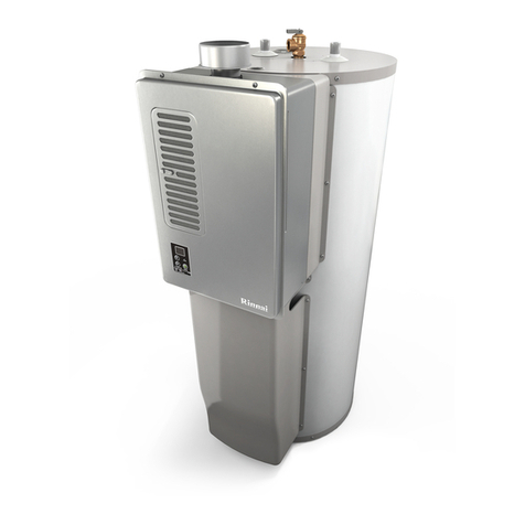
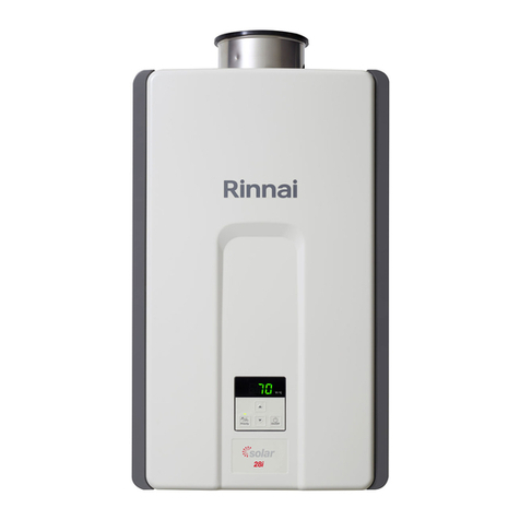
  9. Rinnai C42e User manual

Rinnai C42e User manual

This manual suits for next models

30

Other Rinnai Water Heater manuals

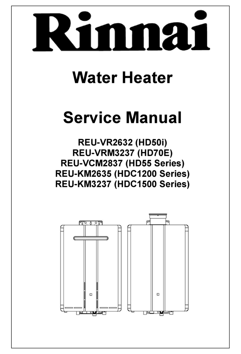
Rinnai V75i User manual

Rinnai

Rinnai V75i User manual

Rinnai REU-VEP2730FFD-US User manual

Rinnai

Rinnai REU-VEP2730FFD-US User manual

Rinnai Circ-Logic RU80e User manual

Rinnai

Rinnai Circ-Logic RU80e User manual

Rinnai CU199i User manual

Rinnai

Rinnai CU199i User manual

Rinnai Smart Cylinders Series Instructions for use

Rinnai

Rinnai Smart Cylinders Series Instructions for use

Rinnai INFINITY 26i User manual

Rinnai

Rinnai INFINITY 26i User manual

Rinnai RH180 User manual

Rinnai

Rinnai RH180 User manual

Rinnai Circ-Logic RU80i User manual

Rinnai

Rinnai Circ-Logic RU80i User manual

Rinnai Continuous Flow Water Heaters User manual

Rinnai

Rinnai Continuous Flow Water Heaters User manual

Rinnai Circ-Logic RU98i User manual

Rinnai

Rinnai Circ-Logic RU98i User manual

Rinnai Demand Rapid DD1200E315N Instructions for use

Rinnai

Rinnai Demand Rapid DD1200E315N Instructions for use

Rinnai Continuous Flow Water Heaters User manual

Rinnai

Rinnai Continuous Flow Water Heaters User manual

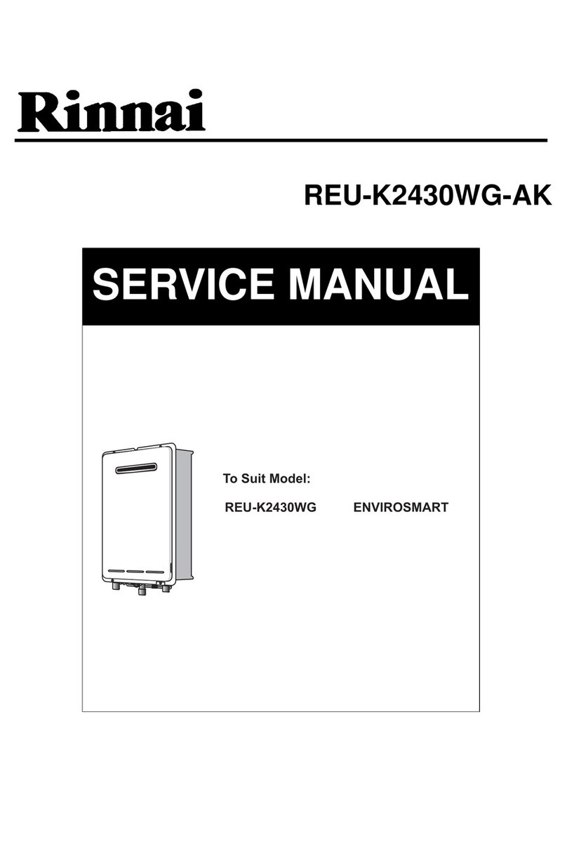
Rinnai REU-K2430WG User manual

Rinnai

Rinnai REU-K2430WG User manual

Rinnai HD70e User manual

Rinnai

Rinnai HD70e User manual

Rinnai RBOX02F User manual

Rinnai

Rinnai RBOX02F User manual

Rinnai Infinity 20 External Specification sheet

Rinnai

Rinnai Infinity 20 External Specification sheet

Rinnai REU-V1616WF User manual

Rinnai

Rinnai REU-V1616WF User manual

Rinnai Infinity XR16 User manual

Rinnai

Rinnai Infinity XR16 User manual

Rinnai QRESS80L336 User manual

Rinnai

Rinnai QRESS80L336 User manual

Rinnai Infinity XR16 User manual

Rinnai

Rinnai Infinity XR16 User manual

Rinnai Sensei RUR199i User manual

Rinnai

Rinnai Sensei RUR199i User manual

Rinnai INFINITYREU-V3232W User manual

Rinnai

Rinnai INFINITYREU-V3232W User manual

Rinnai RUS-51FT User manual

Rinnai

Rinnai RUS-51FT User manual

Rinnai Infinity 16 external Specification sheet

Rinnai

Rinnai Infinity 16 external Specification sheet

Popular Water Heater manuals by other brands

clage German pool CEX13 operating instructions

clage

clage German pool CEX13 operating instructions

Noritz proTough NR98SV installation manual

Noritz

Noritz proTough NR98SV installation manual

DeDietrich KALIKO TWH 200 EV Installation and service manual

DeDietrich

DeDietrich KALIKO TWH 200 EV Installation and service manual

veito FLOW Installation and operating instructions

veito

veito FLOW Installation and operating instructions

ICI Caldaie COSMOGAS AGUATANK 150 Instructions for installation, use and maintenance manual

ICI Caldaie

ICI Caldaie COSMOGAS AGUATANK 150 Instructions for installation, use and maintenance manual

Savio Laser 11 A Instruction manual for installation and use

Savio

Savio Laser 11 A Instruction manual for installation and use

Kenmore 153.582400 Use & care guide

Kenmore

Kenmore 153.582400 Use & care guide

STIEBEL ELTRON Eltronom SHU 5 S Operating and installation instructions

STIEBEL ELTRON

STIEBEL ELTRON Eltronom SHU 5 S Operating and installation instructions

clage E-Mini Series Operating and installation instructions

clage

clage E-Mini Series Operating and installation instructions

Solar SunX 317365-002 instruction manual

Solar

Solar SunX 317365-002 instruction manual

Bradford White EF Series Service manual

Bradford White

Bradford White EF Series Service manual

Dimplex ECSd125-580 Installation and user instructions

Dimplex

Dimplex ECSd125-580 Installation and user instructions

Dux 32FCR6N installation manual

Dux

Dux 32FCR6N installation manual

Noritz N-132M Owner's guide and installation manual

Noritz

Noritz N-132M Owner's guide and installation manual

TESY GCV7/4S 10047 Instructions for use and maintenance

TESY

TESY GCV7/4S 10047 Instructions for use and maintenance

A.O. Smith Gphe 50 instruction manual

A.O. Smith

A.O. Smith Gphe 50 instruction manual

Toyotomi Oil Miser OM-148 (Type D) Operation and maintenance instructions

Toyotomi

Toyotomi Oil Miser OM-148 (Type D) Operation and maintenance instructions

Koryo KWHZF15Y user manual

Koryo

Koryo KWHZF15Y user manual

manuals.online logo
manuals.online logoBrands
  • About & Mission
  • Contact us
  • Privacy Policy
  • Terms and Conditions

Copyright 2025 Manuals.Online. All Rights Reserved.

Tankless Water Heater
Service Manual
Key to Trade Names in this Manual:
R/C Indicates both the residential and
commercial versions. R/C42e includes
R42e and C42e.
RC Indicates condensing water heater models.
(PLUS) Indicates that the Designer Plus models are
included. R/C85ePLUS includes R85e,
C85e, and R85ePLUS. On the side of the
water heater, the trade name includes a
“D”, as in R85De.
(ASME) Indicates that the ASME models are
included. R98LSe(ASME) includes the
R98LSe and R98LSeASME.
-VA,-VB The trade names R75LSe, R75LSi,
R94LSe, and R94LSi have been given to
both the VA and VB series of water
heaters. Pay close attention to the
particular model number when referencing
electrical diagnostics, wire diagrams, gas
pressures, replacement instructions, and
for parts. When there is a difference –VA
or –VB will be specified.
Model with
valves in carton Equivalent Model
RV53e V53e
RV53i V53i
RL75e R75LSe-VB
RL75i R75LSi-VB
RL94e R94LSe-VB
RL94i R94LSi-VB
RC80e RC80HPe
RC80i RC80HPi
RC98e RC98HPe
RC98i RC98HPi
Some of the trade names for models were changed
to indicate that their cartons included isolation valves
and a pressure relief valve. For service and repair
purposes the table below shows the equivalent
models.
R/C42e, R/C53e 10 28 41 49 54 59 69
R70e,
R/C85e(PLUS) 12 29 43 50 56 65 72
R/C53i(PLUS),
R/C85i(PLUS) 12 30 43 51 56 65 76
R/C98e(ASME) 14 31 45 52 56 67 80
R/C98i(ASME) 14 31 45 52 56 67 82
V53e, R63LSe 16 32 41 49 55 60 69
R50LSi,
R75LSi-VA 18 33 43 51 56 63 76
R63LSe2,
R75LSe-VA 18 33 43 50 56 63 72
R94LSe-VA 18 33 43 50 56 63 72
R94LSi-VA 18 33 43 51 56 63 76
R75LSe-VB 20 34 47 50 56 63 72
R75LSi-VB 20 34 47 51 56 63 76
R94LSe-VB 20 34 47 50 56 63 72
R94LSi-VB 20 34 47 51 56 63 76
V53i 20 35 43 51 56 63 76
R98LSe(ASME) 22 36 45 52 58 67 80
R98LSi(ASME) 22 36 45 52 58 67 82
RC80HPe 24 37 47 53 56 68 85
RC80HPi 24 37 47 53 56 68 88
RC98HPe 26 38 48 53 56 68 91
RC98HPi 26 38 48 53 56 68 94
DIAGNOSTICS
WIRE DIAGRAM
GAS CONTROL
FAN
PC BOARD
WATER FLOW
CONTROL
HEAT
EXCHANGER
MODELS
This manual provides service information for the models
below. This table cross references each model to the
applicable page number for internal component
replacement instructions.
100000098 Rev B
Rinnai Water Heater Service Manual 2 100000098 Rev B
Table of Contents
General Information....................................................3
Specifications.......................................................... 4-6
Schematic Diagrams............................................... 7-9
Diagnostic Codes.................................................. 8-10
Electrical Diagnostic Points
R/C42e, R/C53e, ................................................. 10, 11
R70e, R/C85e(PLUS),
R/C53i(PLUS), R/C85i(PLUS) ............................. 12, 13
R/C98e(ASME), R/C98i(ASME)........................... 14, 15
V53e, R63LSe...................................................... 16, 17
R50LSi, R63LSe2, R75LSe-VA, R75LSi-VA,
R94LSe-VA, R94LSi-VA ...................................... 18, 19
V53i, R75LSe-VB, R75LSi-VB,
R94LSe-VB, R94LSi-VB ...................................... 20, 21
R98LSe(ASME), R98LSi(ASME) ......................... 22, 23
RC80HPe, RC80HPi ............................................ 24, 25
RC98HPe, RC98HPi ............................................ 26, 27
Wire Diagrams
R/C42e, R/C53e..........................................................28
R70e, R/C85e(PLUS)..................................................29
R/C53i(PLUS), R/C85i(PLUS).....................................30
R/C98e(ASME), R/C98i(ASME)..................................31
V53e, R63LSe.............................................................32
R50LSi, R63LSe2, R75LSe-VA, R75LSi-VA,
R94LSe-VA, R94LSi-VA .............................................33
R75LSe-VB, R75LSi-VB, R94LSe-VB, R94LSi-VB ....34
V53i .............................................................................35
R98LSe(ASME), R98LSi(ASME) ................................36
RC80HPe, RC80HPi ...................................................37
RC98HPe, RC98HPi ...................................................38
Flushing the Heat Exchanger...................................39
Manual Draining of the Water Heater......................40
Gas Control Assembly
R/C42e, R/C53e, V53e, R63LSe ......................... 41, 42
R/C53i(PLUS), R70e, R/C85e(PLUS), R/C85i(PLUS),
R50LSi, V53i, R63LSe2, R75LSe-VA, R75LSi-VA,
R94LSe-VA, R94LSi-VA ...................................... 43, 44
R/C98e(ASME), R/C98i(ASME),
R98LSe(ASME), R98LSi(ASME) ......................... 45, 46
RC80HPe, RC80HPi, R75LSe-VB, R75LSi-VB,
R94LSe-VB, R94LSi-VB .............................................47
RC98HPe, RC98HPi ...................................................48
Fan
R/C42e, R/C53e, V53e, R63LSe................................ 49
R70e, R/C85e(PLUS), R63LSe2,
R75LSe, R94LSe........................................................ 50
R/C53i(PLUS), R/C85i(PLUS), R50LSi,
V53i, R75LSi, R94LSi................................................. 51
R/C98e(ASME), R/C98i(ASME),
R98LSe(ASME), R98LSi(ASME) ............................... 52
RC80HPe, RC80HPi, RC98HPe, RC98HPi............... 53
PC Board
R/C42e, R/C53e ......................................................... 54
V53e, R63LSe ............................................................ 55
R/C53i(PLUS), R70e, R/C85e(PLUS),
R/C85i(PLUS), R50LSi, R63LSe2, V53i,
R75LSe, R75LSi, R94LSe, R94LSi,
RC80HPe, RC80HPi, RC98HPe, RC98HPi.......... 56-57
R/C98e(ASME), R/C98i(ASME),
R98LSe(ASME), R98LSi(ASME) ............................... 58
Water Flow Control Assembly
R/C42e, R/C53e ................................................... 59, 60
V53e, R63LSe ...................................................... 61, 62
R/C53i, R70e, R50LSi, R63LSe2, V53i,
R75LSe, R75LSi................................................... 63, 64
R/C85e(PLUS), R/C85i(PLUS),
R94LSe, R94LSi................................................... 65, 66
R/C98e(ASME), R/C98i(ASME),
R98LSe(ASME), R98LSi(ASME) ............................... 67
RC80HPe, RC80HPi, RC98HPe, RC98HPi............... 68
Heat Exchanger
R/C42e, R/C53e, V53e, R63LSe........................... 69-71
R70e, R/C85e(PLUS), R63LSe2,
R75LSe, R94LSe................................................... 72-75
R/C53i(PLUS), R/C85i(PLUS), V53i,
R50LSi, R75LSi, R94LSi ....................................... 76-79
R/C98e(ASME), R98LSe(ASME) .......................... 80-81
R/C98i(ASME), R98LSi(ASME) ............................ 82-84
RC80HPe .............................................................. 85-87
RC80HPi................................................................ 88-90
RC98HPe .............................................................. 91-93
RC98HPi................................................................ 94-96
Gas Pressure Setting Procedure....................... 97-98
Manifold Pressure Settings.............................. 99-105
Dip Switches.................................................... 106-108
Rinnai Water Heater Service Manual 3 100000098 Rev B
General Information
Safety Definitions
This is the safety alert symbol. This symbol alerts you to potential hazards that can kill or hurt you and
others.
Indicates an imminently hazardous situation which, if not avoided, will result in death or
serious injury.
Indicates a potentially hazardous situation which, if not avoided, could result in death or
serious injury.
Indicates a potentially hazardous situation which, if not avoided, could result in minor or
moderate injury. It may also be used to alert against unsafe practices.
DANGER
CAUTION
WARNING
Recommended Tools
• Volt/Ohm/Amp meter with test probes
• Digital manometer or U tube type manometer with 14 inch water column (W.C.) scale, a hose and two 1/8 inch
taps
• assorted wrenches including a 3/16 Allen wrench
• assorted screw drivers
• leak solution or leak detector
• Teflon tape
Using this Manual
Repairs should be performed by a qualified service technician.
The following information can be referenced for additional information.
• Operation and Installation Manual
• Hot Water System Design Manual
• Technical Sheets
• Technical Bulletins
Technical Support
Technicians are available to assist in servicing issues. Contact Rinnai Technical Services at 1-800-621-9419.
WARNING
There are a number of live tests that are required when fault finding this product. Extreme care should be used at
all times to avoid contact with energized components inside the water heater. Before checking for resistance
readings disconnect the power source to the unit and isolate the item from the circuit (unplug it).
If any of the original wire as supplied with the appliance must
be replaced, it must be replaced with type 18 AWG wire or its
equivalent.
Label all wires prior to disconnection when
servicing controls. Wiring errors can cause
improper and dangerous operation.
CAUTION
Rinnai Water Heater Service Manual 4 100000098 Rev B
Specifications
Trade Name Model Max. BTU Min. BTU Max Flow [1]
gal/min (liters/min) Temperature Range
C42e REU-V1616WC 120,000
17,100 (NG)
17,800 (LP) 4.2 (16) 120 - 185 ºF (49-85 ºC)
C53e REU-V2020WC 150,000
19,000 (NG)
20,200 (LP) 5.3 (20) 120 - 185 ºF (49-85 ºC)
C85e REU-V2532WC 199,000 15,000 8.5 (32) 98 - 185 ºF (37-85 ºC)
C85ePLUS REU-V2532WCD 199,000 15,000 8.5 (32) 98 - 185 ºF (37-85 ºC)
C98e REU-V3237WC 237,000 19,000 9.8 (37) 98 - 185 ºF (37-85 ºC)
C98eASME REU-V3237WC-ASME 237,000 19,000 9.8 (37) 98 - 185 ºF (37-85 ºC)
V Series - Commercial - Outdoor
Trade Name Model Max. BTU Min. BTU Max Flow [1]
gal/min (liters/min) Temperature Range
C53i REU-V2520FFUC 180,000 15,000 5.3 (20) 120 - 185 ºF (49-85 ºC)
C53iPLUS REU-V2520FFUCD 180,000 15,000 5.3 (20) 120 - 185 ºF (49-85 ºC)
C85i REU-V2532FFUC 180,000 15,000 8.5 (32) 98 - 185 ºF (37-85 ºC)
C85iPLUS REU-V2532FFUCD 180,000 15,000 8.5 (32) 98 - 185 ºF (37-85 ºC)
C98i REU-V3237FFUC 237,000 19,000 9.8 (37) 98 - 185 ºF (37-85 ºC)
C98iASME REU-V3237FFUC-ASME 237,000 19,000 9.8 (37) 98 - 185 ºF (37-85 ºC)
V Series - Commercial - Indoor
Trade Name Model Max. BTU Min. BTU Max Flow [1]
gal/min (liters/min) Temperature Range
R42e REU-V1616W 120,000
17,100 (NG)
17,800 (LP) 4.2 (16) 98 - 140 ºF (37-60 ºC)
R53e REU-V2020W 150,000
19,000 (NG)
20,200 (LP) 5.3 (20) 98 - 140 ºF (37-60 ºC)
R70e REU-V2526W 199,000 15,000 7.0 (26) 98 - 140 ºF (37-60 ºC)
R85e REU-V2532W 199,000 15,000 8.5 (32) 98 - 140 ºF (37-60 ºC)
R85ePLUS REU-V2532WD 199,000 15,000 8.5 (32) 98 - 140 ºF (37-60 ºC)
R98e REU-V3237W 237,000 19,000 9.8 (37) 98 - 140 ºF (37-60 ºC)
R98eASME REU-V3237W-ASME 237,000 19,000 9.8 (37) 98 - 140 ºF (37-60 ºC)
V Series - Residential - Outdoor
[1] Minimum activation flow is approximately 0.6 gallons/minute (2.3 liters/min)
Trade Name Model Max. BTU Min. BTU Max Flow [1]
gal/min (liters/min) Temperature Range
R53i REU-V2520FFU 180,000 15,000 5.3 (20) 98 - 140 ºF (37-60 ºC)
R53iPLUS REU-V2520FFU 180,000 15,000 5.3 (20) 98 - 140 ºF (37-60 ºC)
R85i REU-V2532FFU 180,000 15,000 8.5 (32) 98 - 140 ºF (37-60 ºC)
R85iPLUS REU-V2532FFUD 180,000 15,000 8.5 (32) 98 - 140 ºF (37-60 ºC)
R98i REU-V3237FFU 237,000 19,000 9.8 (37) 98 - 140 ºF (37-60 ºC)
R98iASME REU-V3237FFU-ASME 237,000 19,000 9.8 (37) 98 - 140 ºF (37-60 ºC)
V Series - Residential - Indoor
Rinnai Water Heater Service Manual 5 100000098 Rev B
Specifications
[1] Minimum activation flow is approximately 0.6 gallons/minute (2.3 liters/min)
[2] Max temperature is 160 ºF (71 ºC) with the MCC-91 controller for commercial and hydronic applications only.
[3] Max temperature is 185 ºF (85 ºC) with the MCC-91 controller for commercial and hydronic applications only.
Trade Name Model Max. BTU Min. BTU Max Flow [1]
gal/min (liters/min) Temperature Range
R63LSe REU-VA2024WD-US 150,000 21,500 (NG)
20,600 (LP) 6.3 (24)
98 - 140 ºF (37-60 ºC) [2]
R63LSe2 REU-VA2024WD(A)-US 150,000 15,000 6.3 (24)
R75LSe REU-VA2528WD-US 199,000 15,000 7.5 (28)
R75LSe REU-VA2528WD(A)-US
REU-VA2528WD(A)-UC 180,000 15,000 7.5 (28)
R94LSe REU-VA2535WD-US
REU-VA2535WD-UC 199,000 15,000 9.4 (35)
R98LSe REU-VA3237W-US 237,000 19,000 9.8 (37)
R98LSeASME REU-VA3237W-ASME 237,000 19,000 9.8 (37)
98 - 140 ºF (37-60 ºC) [3]
VA Series (LS Series) - Residential or Commercial - Outdoor
Trade Name Model Max. BTU Min. BTU Max Flow [1]
gal/min (liters/min) Temperature Range
R50LSi REU-VA2019FFUD-US 150,000 15,000 5.0 (19)
98 - 140 ºF (37-60 ºC) [2]
R75LSi REU-VA2528FFUD-US 199,000 15,000 7.5 (28)
R75LSi
REU-VA2528FFUD(A)-
US
REU-VA2528FFUD(A)-
UC
180,000 15,000 7.5 (28)
R94LSi REU-VA2535FFUD-US
REU-VA2535FFUD-UC 199,000 (NG)
190,000 (LPG) 15,000 9.4 (35)
98 - 140 ºF (37-60 ºC) [3]
R98LSi REU-VA3237FFU-US 237,000 19,000 9.8 (37)
R98LSiASME REU-VA3237FFU-ASME 237,000 19,000 9.8 (37)
VA Series (LS Series) - Residential or Commercial - Indoor
Trade Name Model Max. BTU Min. BTU Max Flow [1]
gal/min (liters/min) Temperature Range
V53e REU-VAM1620W-US 120,000
19,000 (NG)
20,200 (LP) 5.3 (20) 98 - 140 ºF (37-60 ºC)
VA Series - Residential - Outdoor
Rinnai Water Heater Service Manual 6 100000098 Rev B
Specifications
[1] Minimum activation flow is approximately 0.4 gallons/minute (1.5 liters/min); minimum flow is approximately
0.26 gallons/minute (1 liter/min).
[2] Max temperature is 160 ºF (71 ºC) with the MCC-91 controller for commercial and hydronic applications only.
[3] Max temperature is 185 ºF (85 ºC) with the MCC-91 controller for commercial and hydronic applications only.
[4] Minimum activation flow is approximately 0.6 gallons/minute (2.3 liters/min).
Trade Name Model Max. BTU Min. BTU Max Flow [1]
gal/min (liters/min) Temperature Range
R75LSe,
RL75e REU-VB2528WD-US 180,000 9,900 (NG)
10,300 (LPG) 7.5 (28) 98 - 140 ºF (37-60 ºC) [2]
R94LSe,
RL94e REU-VB2735WD-US 199,000 9,900 (NG)
10,300 (LPG) 9.4 (35) 98 - 140 ºF (37-60 ºC) [3]
VB Series (LS Series) - Residential or Commercial - Outdoor
Trade Name Model Max. BTU Min. BTU Max Flow [1]
gal/min (liters/min) Temperature Range
R75LSi, RL75i REU-VB2528FFUD-US 180,000 9,900 (NG)
10,300 (LPG) 7.5 (28) 98 - 140 ºF (37-60 ºC) [2]
R94LSi, RL94i REU-VB2735FFUD-US 199,000 (NG)
190,000 (LPG)
9,900 (NG)
10,300 (LPG) 9.4 (35) 98 - 140 ºF (37-60 ºC) [3]
VB Series (LS Series) - Residential or Commercial - Indoor
Trade Name Model Max. BTU Min. BTU Max Flow [4]
gal/min (liters/min) Temperature Range
V53i, RV53i REU-VB2020FFU-US 150,000 15,000 5.3 (20) 98 - 140 ºF (37-60 ºC)
VB Series - Residential - Indoor
Trade Name Model Max. BTU Min. BTU Max Flow [1]
gal/min (liters/min) Temperature Range
RC80HPe,
RC80e REU-KA2530WD-US 157,000 9,500 (NG)
10,300 (LPG) 8.0 (30)
RC98HPe,
RC98e REU-KA3237WD-US 199,000 9,500 (NG)
10,300 (LPG) 9.8 (37)
98 - 140 ºF (37-60 ºC) [3]
Condensing Series - Residential or Commercial - Outdoor
Trade Name Model Max. BTU Min. BTU Max Flow [1]
gal/min (liters/min) Temperature Range
RC80HPi,
RC80i REU-KA2530FFUD-US 157,000 9,500 (NG)
10,300 (LPG) 8.0 (30)
RC98HPi,
RC98i REU-KA3237FFUD-US 199,000 9,500 (NG)
10,300 (LPG) 9.8 (37)
98 - 140 ºF (37-60 ºC) [3]
Condensing Series - Residential or Commercial - Indoor
Rinnai Water Heater Service Manual 7 100000098 Rev B
Diagnostic Codes
The Rinnai water heater has the ability to check its own operation continuously. If a fault occurs, an error code
will flash on the display of the remote controller. This assists with diagnosing the fault and may enable you to
overcome a problem without a service call.
Some of the checks below may need to be done by a qualified service technician. Call a
service technician for any remedy that involves gas or electricity. Call a service
technician if you have any doubt or reservation about performing the remedy yourself.
WARNING
Accessing Operating Information
To display the most recent error codes press and hold the “On/Off” button for 2 seconds. While holding the “On/
Off” button press the ▲button. The last 9 error codes will flash one after the other. To exit this mode press the
“On/Off” and ▲button as before.
To display the water flow through the water heater press and hold the ▲button for 2 seconds and without
releasing the ▲button press the “On/Off” button.
To display the outlet water temperature press and hold the ▼button for 2 seconds and without releasing the ▼
button press the “On/Off” button.
Models MC-91 and MCC-91
1. Water Flow Begins.
• Water Flow Sensor sends pulses to the PC
Board.
• PC Board senses flow.
• Firing Sequence begins when the flow exceeds
the minimum activation flow rate.
2. Firing Sequence.
• PC Board monitors inlet/outlet water
temperature, temperature set point, and water
flow rate.
• Combustion fan energized. Purges combustion
chamber.
• Spark igniter begins sparking.
• Gas control valve opens to minimum fire rate.
• Flame rod(s) proves ignition.
• Spark igniter stops sparking.
3. Normal Operation.
• PC Board monitors flame rod, fan motor
frequency, outlet water temperature, controller
temperature set point and water flow rate.
• Gas control valve modulates gas input to
required firing rate.
• Combustion fan speed is adjusted for the
required firing rate.
• Water flow control valve is adjusted as needed.
4. Shut-down Sequence.
• Shut-down begins when the PC Board senses
the minimum flow rate which is 0.26 - 0.5 gpm
depending on model.
• Gas control valve closes.
• Water flow control valve resets to standby
position.
• Combustion fan runs for a short period of time
at low speed.
5. Standby Mode.
• PC Board monitors water temperature and
remote controls.
• Freeze protection is activated as needed.
Operation
Rinnai Water Heater Service Manual 8 100000098 Rev B
Diagnostic Codes
Code Definition Remedy
02 No burner operation during
freeze protection mode
ONLY FOR NON-
CONDENSING MODELS
Service Call
03 Power interruption during Bath
Fill (Water will not flow when
power returns).
Turn off all hot water taps. Press ON/OFF twice.
10 Air Supply or Exhaust
Blockage
Ensure Rinnai approved venting materials are being used.
Check that nothing is blocking the flue inlet or exhaust.
Check all vent components for proper connections.
Ensure vent length is within limits.
For non-condensing models, ensure condensation collar was installed correctly.
Verify dip switches are set properly.
Check fan for blockage.
Check the fins in the heat exchanger.
For condensing models, Burner Sensor Error (see code 31)
11 No Ignition Check that the gas is turned on at the water heater, gas meter, or cylinder.
Ensure gas type and pressure is correct.
Ensure gas line, meter, and/or regulator is sized properly.
Bleed all air from gas lines.
Verify dip switches are set properly.
Ensure appliance is properly grounded.
Disconnect EZConnect or MSA controls to isolate the problem.
Ensure igniter is operational.
Check igniter wiring harness for damage.
Check gas solenoid valves for open or short circuits.
Remove burner cover and ensure all burners are properly seated.
Remove burner plate and inspect burner surface for condensation or debris.
If flame is visible, check the flame rod circuit.
12 Flame Failure Check that the gas is turned on at the water heater and gas meter. Check for obstructions in
the flue outlet.
Ensure gas line, meter, and/or regulator is sized properly.
Ensure gas type and pressure is correct.
Bleed all air from gas lines.
Ensure proper Rinnai venting material was installed.
For non-condensing models, ensure condensation collar was installed properly.
Ensure vent length is within limits.
Verify dip switches are set properly.
Ensure appliance is properly grounded.
Disconnect keypad.
Disconnect EZConnect or MSA controls to isolate the problem.
Check power supply for loose connections.
Check power supply for proper voltage and voltage drops.
Ensure flame rod wire is connected.
Ensure flame rod is in proper position (wire should connect at 6 o’clock position).
Remove flame rod and check for carbon build-up; clean with sand paper or emery cloth.
Disconnect and reconnect all wiring harnesses on unit and PC board.
Check all components for electrical short.
Check gas solenoid valves for open or short circuits.
Remove burner plate and inspect burner surface for condensation or debris.
Check the ground wire for the PC board.
14 Thermal Fuse Check gas type of unit and ensure it matches gas type being used.
Check for restrictions in air flow around unit and vent terminal.
Check for low water flow in a circulating system causing short-cycling.
Ensure dip switches are set to the proper position.
Check for foreign materials in combustion chamber and/or exhaust piping.
Check heat exchanger for cracks and/or separations.
Check heat exchanger surface for hot spots which indicate blockage due to scale build-up.
Refer to instructions in manual for flushing heat exchanger. Hard water must be treated
to prevent scale build up or damage to the heat exchanger.
Measure resistance of safety circuit.
Ensure high fire and low fire manifold pressure is correct.
Check for improper conversion of product.
16 Over Temperature Warning Check for restrictions in the intake and exhaust system.
Check for low water flow in a circulating system causing short-cycling.
Check for foreign materials in combustion chamber and/or exhaust piping.
Check for blockage in the heat exchanger.
Rinnai Water Heater Service Manual 9 100000098 Rev B
Code Definition Remedy
25
Condensate Trap Error
ONLY FOR
CONDENSING MODELS
Condensate container is full.
Check condensate drain for blockage.
Replace condensate trap.
31 Burner Sensor Error
ONLY FOR VB AND
CONDENSING INDOOR
MODELS
Measure resistance of sensor.
Replace sensor.
32 Outgoing Water
Temperature Sensor
Check sensor wiring for damage.
Measure resistance of sensor.
Clean sensor of scale build-up.
Replace sensor.
33 Heat Exchanger Outgoing
Temperature Sensor
Check sensor wiring to be sure it has not been short circuited.
Measure resistance of sensor.
Clean sensor of scale build-up.
Replace sensor.
34 Combustion Air
Temperature Sensor
ONLY FOR INDOOR
NON-CONDENSING
MODELS (EXCEPT
R98LSi)
Check for restrictions in the intake and exhaust system.
Check sensor wiring for damage.
Measure resistance of sensor.
Clean sensor of scale build-up.
Check the fan blade to be sure it is tight on motor shaft and is in good condition.
Replace sensor.
52 Modulating Solenoid
Valve Signal Abnormal
Check modulating gas solenoid valve wiring harness for loose or damaged terminals.
Measure resistance of valve coil.
61 Combustion Fan Failure Ensure fan will turn freely.
Check wiring harness to motor for damaged and/or loose connections.
Measure resistance of motor winding.
Check for proper voltage from PC board.
65 Water Flow Control The water flow control valve has failed to close during the bath fill function. Immediately turn off
the water and discontinue the bath fill function. Contact a state qualified or licensed contractor to
service the appliance.
70 Sensor Harness
Connection
ONLY FOR
CONDENSING MODELS
Check PC board switches (in the bank of 6 switches, #2 should be on for indoor models and off for
outdoor models)
Check the connection harness at the E connection on the PC board. Outdoor models should have
2 orange cables at #7 and 8 positions. Indoor models should not have cables at these positions. If
this is incorrect then replace the sensor harness.
Replace PC board
71 Solenoid Valve Circuit For non-condensing, check wiring harness to all solenoids for damage and/or loose connections.
Measure resistance of each solenoid valve coil.
For condensing, replace PC board.
72 Flame Sensing Device Verify flame rod is touching flame when unit fires.
Check all wiring to flame rod.
Remove flame rod and check for carbon build-up; clean with sand paper or emery cloth.
Check inside burner chamber for any foreign material blocking flame at flame rod.
Measure micro amp output of sensor circuit with flame present.
Replace flame rod.
73 Burner Sensor Circuit
ONLY FOR VB AND
CONDENSING INDOOR
MODELS
Check sensor wiring and PC board to be sure they have not been damaged.
Replace sensor.
LC Scale Build-up in Heat
Exchanger (when
checking maintenance
code history, “00” is
substituted for “LC”)
Flush heat exchanger. Refer to instructions in manual. Hard water must be treated to prevent
scale build up or damage to the heat exchanger.
Replace heat exchanger.
NOTE: The LC code is the only code that will allow the unit to keep running. The display will
alternate between the LC code and the temperature setting. The controller will continue to beep.
The LC code will reset if power is turned off and then on.
No
code
Nothing happens when
water flow is activated.
On controller, verify if unit is sensing flow. If not then check the items below. If unit is
sensing flow then check the heat exchanger and outlet thermistors.
Clean inlet water supply filter.
On new installations ensure hot and cold water lines are not reversed.
Check for cold to hot cross over. Isolate circulating system if present. Turn off cold water to the
unit, open pressure relief valve; if water continues to flow, there is bleed over in your plumbing.
Verify you have at least the minimum flow rate required to fire unit.
Verify turbine spins freely.
Measure the resistance of the water flow control sensor.
If the display is blank and clicking is coming from the unit, disconnect the water flow servo motor
(RD, BL, BR, GY, YL). If the display come on then replace the water flow servo motor.
Diagnostic Codes
Rinnai Water Heater Service Manual 10 100000098 Rev B
Electrical Diagnostic Points
Wire Color Voltage Resistance Connector No. Pin No.’s
(TR) Transformer
Black - White 90 - 100 VAC 51-63 ohms F2 1 ~ 2
Blue - Brown 108 - 132 VAC 51-63 ohms F3 1 ~ 3
(SV1, SV2, SV3, POV) Gas Valve and Modulating Solenoids
(Main) Pink - Black
80 - 100 VDC 1.7 - 2 K ohms
E1 1 ~ 2
(SV1) Black - Blue E2 1 ~ 2
(SV2) Black - Yellow E3 1 ~ 2
(POV) Pink - Pink 2 - 15 VDC 67 - 81 ohms C2 1 ~ 2
(M) Water Flow Servo
Red - Blue 11 - 13 VDC 22 - 26 ohms B1 1 ~ 2
Gray - Brown 4 - 6 VDC N/A B1 6 ~ 3
Gray - Yellow N/A N/A B1 6 ~ 5
Gray - Orange 11 - 14 VDC N/A B1 6 ~ 4
NOTE: At the B connector on the PCB: gray wire turns to black, orange wire turns to red
(QS) Water Flow Sensor
Black - Red 11 - 13 VDC 5.5 - 6.2 K ohms B3 3 ~ 1
Yellow - Black 4 - 7 VDC 1 - 1.4 mega ohms B3 2 ~ 3
(IG) Ignition System
Gray - Gray 90 - 100 VAC N/A F1 1 ~ 2
(FM) Combustion Fan Motor
Red - Black 6 - 45 VDC N/A A1 1 ~ 2
White - Black 5 - 10 VDC 9.2 - 9.4 K ohms A1 2 ~ 4
Yellow - Black 11 ~ 13 VDC 3.5 - 3.9 K ohms A1 2 ~ 3
With the meter set on hertz scale, 60-350 hertz should be across the red and yellow wires at
terminals 2 and 3.
R/C42e, R/C53e