Rinnai Infinity Series User manual

1
Infinity Storage Packs
Installation Manual
IMPORTANT
Read these instructions carefully before attempting
installation or use of this appliance. All work must be carried
out by competent persons.

2
CONTENTS 2
USER INSTRUCTIONS
Warnings 3
Building Operator's Duty of Care 5
Rinnai Storage Package Contents 6
Basic Operating Principle 7
INSTALLATION
Planning out the Site 8
Water Heater Pipework 9
Schematics 10
Unvented Kit 12
Hot Water Storage Cylinder 14
Cylinder Dimensions 15
System Design Recommendations 18
System Controls 20
Wiring Diagram 21
Extra Pump 22
Extra Cylinder 22
Pump Data 23
Commissioning Procedure 24
Commissioning Record 26
Service Record 27
UK Warranty 28
Warranty Registration 30
Contact 32
CONTENTS

3
THIS MANUAL SHOULD BE READ IN
CONJUNCTION WITH THE
INSTALLATION MANUAL FOR THE
RINNAI WATER HEATERS
PLEASE READ ALL FOLLOWING
INSTRUCTIONS FULLY
FAILURE TO FOLLOW THESE
INSTRUCTIONS AND PIPING
SCHEMATICS IMPLICITLY COULD
CAUSE SERIOUS INJURY AND DAMAGE
TO PROPERTY.
ANY WARRANTY CLAIMS WILL BE
NEGATED AND RINNAI UK WILL NOT
BE HELD ACCOUNTABLE FOR ANY
DAMAGE OR THIRD PARTY CLAIMS
WARNINGS

4
Persons carrying out installation work on the Rinnai Infinity Hot Water Package require the following
certificates
For any gas work carried out: Gas Safe Register Registration and ACS certification For installation of
the Hot water system: proof of competence which can be shown through a Registered Operative
Identity Card for the installation of Unvented Domestic Hot Water Systems or the Association of
Installers of Unvented Hot Water Systems (Scotland and Northern Ireland.) For installation of electrical
wiring: EIC certification. IEE 16th Edition
Building Regulation G3 draws attention to the Building Regulations 1991, especially
Regulation 11(1), 12(4), and 13(3). The following is quoted from these and Building Regulation
G3.
A person who intends to carry out building work or to make a material change of use shall-- give to the
local authority full plans and a building notice accompanied by a statement which specifies:
a: the name, make, model and type of hot water storage system to be installed
b: the name of the body, if any, which has approved or certified that the system is capable of
performing in a way which satisfies the requirements of paragraph G3 of Schedule 1.*
c: the name of the body, if any, which has issued any current registered operative identity card to the
installer or proposed installer of the system.
The full plans shall consist of a description of the proposed building work or material change of use,
and the plans, particulars and statements required.
*In the Secretary of State’s view requirement G3 will be met if a hot water storage system that has a
storage vessel with no vent pipe to the atmosphere:
a: has been installed by a competent person
b: has safety devices that prevent the temperature of the stored water at any time exceeding
100°C;
c: has pipework that safely conveys the discharge of hot water from safety devices to where it is visible
but will cause no danger to persons, in or about the building.
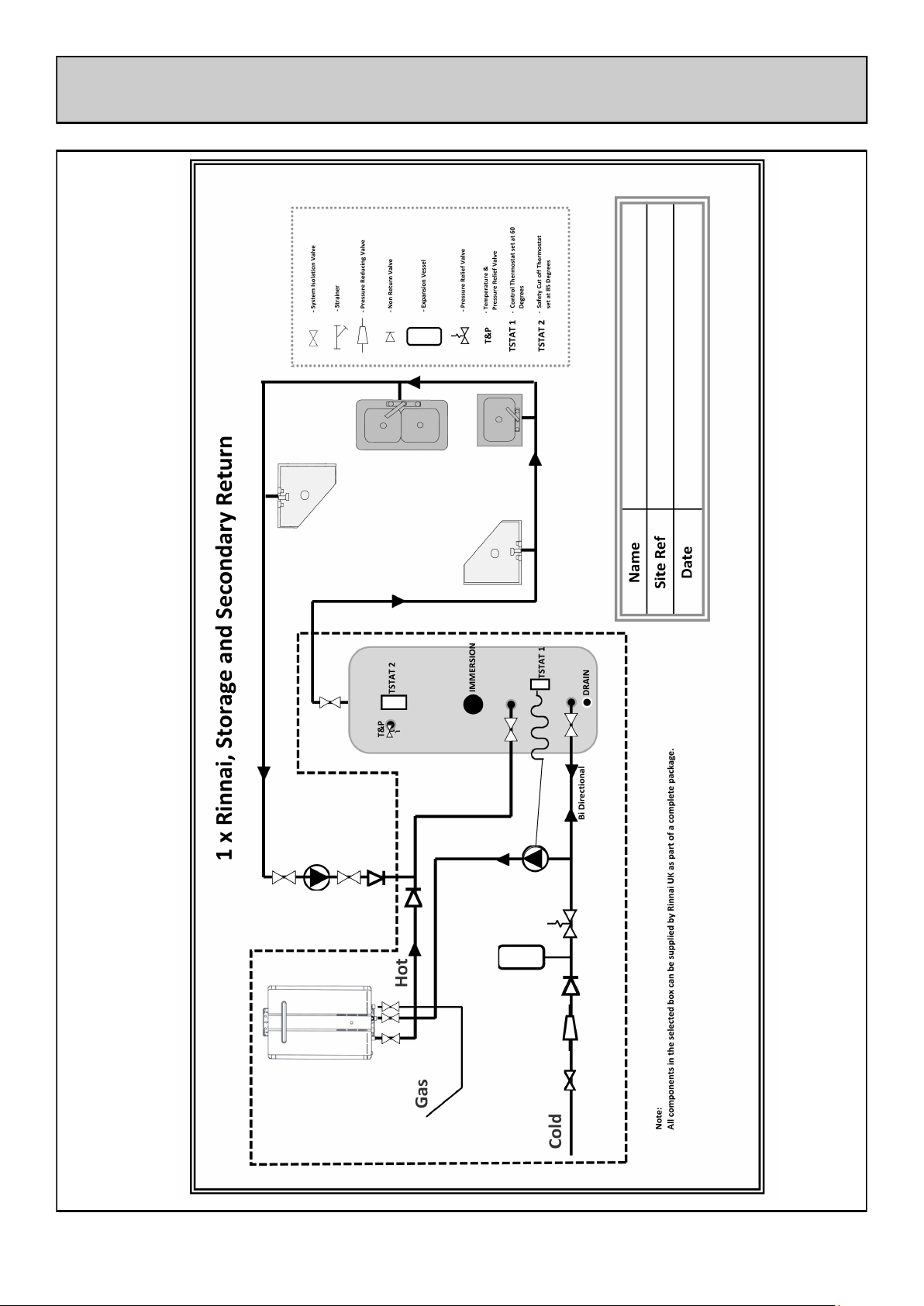
The Rinnai Infinity hot water storage system, like most systems over 150 litres capacity, has been
supplied as a package with the necessary safety devices to prevent the temperature of the stored water
from exceeding 100°C. It is the responsibility of the installer to make sure that proper certification has
been gained, and that the system is installed to the requirements of G3 and of this installation manual.
Additionally the installation must be carried out to the requirements of Building
Regulations issued by the Department of the Environment Building Standards
(Scotland) Regulations.
I.E.E. Wiring regulations for electrical installations. BS 6700 Local byelaws Water regulations Health
and safety at work etc. Act 1974
Such other specifications and regulations that may supersede or complement the above documents.
Additional documents listed in the Infinity water heater manual.
Disposal Information:
Under the laws and local regulations, all items must be disposed separately from household waste.
When this product reaches the end of useful life, it should be taken to a collection point identified by
the local authorities. The recycling of the product at the time of disposal will help conserve natural
resources and ensure that it is recycled in a manner that protects human health and environment.
WARNINGS

5
Any owner of a domestic hot water system has a duty of care to protect employees and the public from
the possible dangers of hot water systems including scalding or Legionella. Although this document is
not intended to give expert advice on ways to avoid these issues it should give a guideline to what
should be done and where more information can be found. The full list of responsibilities can be found
in the following documents
TM13 CIBSE: Minimising the Risk of Legionnaires Disease ACOP L8: The Control of Legionella
Bacteria in Water Systems HSE publication: Legionnaires Disease: A guide for employers Various
other documents that are industry specific such as HSE publication: Controlling Legionella in Nursing
and Residential Homes NHS Estates HTM 2040 The Control of Legionella in Healthcare Premises: a
code of practice. and HTM 2027 Hot and Cold Water Supply, Storage and Mains Services. There are
many industry specific documents regarding the distribution of hot water. These can be found in IP
14/03 from the BRE: Preventing Hot Water Scalding In Bathrooms: Using TMVs
This list is not comprehensive.
The responsibilities, relative to the Rinnai Infinity type of hot water system, can be summarised in the
following way.
Water temperatures in cylinders should always be over 600C. A secondary return must return at over
500C. The water at the furthest outlets must reach 500C within 60 seconds.
Warning signs should be placed over taps where the temperature could exceed 550C. Where people
are at high risk consider thermostatic mixing valves.
A risk assessment should be carried out, by a suitable person, to gauge the associated risk of the hot
water system. This assessment should be reviewed at regular intervals.
Based on this assessment a maintenance regime should be determined. The hot water system and
Infinity water heaters must be serviced annually. This alone is not sufficient. Some parts of the hot
water system, such as rarely used shower heads or terminal fittings, will require frequent maintenance.
Frequent checks should be carried out to ensure the hot water system is operating correctly.
The system must be commissioned by a qualified person.
BUILDING OPERATORS DUTY OF CARE

6
This Rinnai Hot Water Pack should consist of the following:
Set of 3 Valves (Hot, Cold, Gas) Equal to number of heaters
1 x Hot water cylinder
Valve Pack Corresponding to the Size of Hot Water Cylinder
1 x Primary Pump
1 x Mains Valve Kit
1 x Expansion Vessel
1 x TSTAT1 (Control Thermostat)
1 x TSTAT2 (Safety Thermostat/High Limit Thermostat)
1 x Temperature and Pressure Relief Valve
1 x MC91 Controller (for diagnostics only not to be left connected to heater)
1 x Installation Manual and Service Log
Optional Extra
Water Conditioner in Hard Water Areas (recommendation in ACOP L8 2014)
RINNAI STORAGE PACK CONTENTS

7
When the water temperature is below the set point (normally 600C) the thermostat contacts
(TSTAT1) will close and allow power to the circulating, primary pump.
The pump will start circulating water from the bottom of the storage cylinder up through the Rinnai
Water Heater(s) to be heated and returned to the cylinder. The Rinnai Water Heater(s) see this the
same as a hot water tap opening and will ignite and start heating water. (Rinnai Water Heater(s)
should be pre set to 750C on the dip switches)
When the thermostat reaches its set temperature the thermostat contacts open and the circulating
pump will stop. As water has stopped flowing the Rinnai Water Heater(s) will shut off.
It is normal for the burner on the Rinnai Water Heater(s) to modulate back to a low burner rate as
the water temperature within the storage cylinder rises near to thermostat set temperature.
At times of no demand the primary pump will draw water out of the bottom of the cylinder to reheat it as
and when required due to the heat loss of the vessel.
At times of heavy draw off the mains water will feed into the bottom of the cylinder and into the Rinnai
Water Heater(s). The system has been correctly sized to give the right mix of mains water heated to
750C and mains water straight into the cylinder to have no effect on the overall temperature of the hot
water supply.
The system has been designed to allow for an outlet temperature of 600C with an incoming mains
temperature of 100C
BASIC OPERATING PRINCIPLE

8
When choosing the location of the Infinity hot water package the following should be taken
into account.
1. The cylinder has a necessary clearance of 100mm to the back and sides, 600mm to the front, and
200mm above.
2. The water heaters should mount on a wall or suitable framework as near as possible to the storage
cylinder to minimise pipe work losses.
3. There are internal and external water heaters so there are options available in locating the water
heaters. The cylinders must be mounted indoors.
4. There must be enough gas available for the entire load of the water heaters.
5. There must be water and electric available.
6. The floor must be strong enough to support the full weight of the cylinder when full.
7. There should be enough room and lighting to service the units.
8. If the heaters are at high level, or access is by means of a ladder, there should be a ladder or
scaffolding available onsite at all times.
9. There must be suitable drainage available so that if there was a leak at any time from the heaters
or cylinder, including a leak of hot water, it would not cause damage to the building, furnishings, or
inhabitants.
10. There must be a suitable place when using internal units to get the flues out of the building in a
safe manner.
PLANNING OUT THE SITE

9
Flow Rates
The primary pumps supplied with the hot water packages are designed to give a flow rate through
each unit of 16 litres/minute.
The pipework should be sized for a minimal pressure drop through the pipework. The total flow through
the header can be found by multiplying the number of units by 16 l/min.
The branches from the header pipe to and from each heater should be in 22mm.
The following guideline can be used when the heaters are near as possible to the cylinder.
For heaters separated from the cylinder the size of the pipe work may have to be increased. The pipe
sizes given are for Primary pipe work including the cold water header from the primary pump to the last
branch, and the hot water header from the outlet of the first heater to the connection point on the
cylinder.
1 heater: 16 l/min 22 mm
2 heaters: 32 l/min 28 mm
3 heaters: 48 l/min 28 mm
4 heaters: 64 l/min 35 mm
5 heaters: 80 l/min 42 mm
6 heaters: 96 l/min 42 mm
Insulation.
All pipe work should be insulated to minimise heat loss.
WATER HEATER PIPEWORK

10
SCHEMATIC

11
SCHEMATIC

12
The Rinnai Infinity Hot Water Package comes with a full Unvented Kit as required by current
regulations.
The Unvented Kit prevents back siphonage into the water mains supply, takes up the expansion of
water as it is heated, reduces the pressure when necessary, and releases the pressure in the system if
an overpressure situation occurs.
The components in their correct order are shown below. All of these components are supplied with the
package except for the Isolation valve shown.
Unvented Kit Sizes
There are two variations in the sizes of kits these are:
The pipe work bore of the components. The Pipe work bore is based on the maximum flow
rate from taps at any one time.
The size of the Expansion vessel. The expansion vessel is based on the size of the cylinder
and volume of primary pipe work.
Pipe work Bore:
1 inch for max flow rates up to around 50 litre/minute
1.5 inch for max flow rates up to around 120 litre/minute
2 inch for max flow rates up to around 200 litre/minute
(based on max flow velocity of about 1.5 m/s)
Expansion Vessel:
300 litre cylinder: 50 litre expansion vessel
500 litre cylinder: 50 litre or 80 litre expansion vessel
800 litre cylinder: 80 litre cylinder
Y
Pressure
Reducing
Valve with
Gauge
Isolation
Valve
Y
Strainer
Check
Valve
Expansion Vessel
Safety Relief Valve
Tundish
UNVENTED KIT

13
The 1 inch Kit comes with a Caleffi Manifold Valve but all larger sizes have individual components. The
ports for the 1 inch kit are as follows:
UNVENTED KIT

14
The available hot water storage cylinders in the Rinnai Infinity Hot Water Packages are:
300 litre, 500 litre & 800 litre
All Rinnai Storage Vessels are Stainless Steel
Dimensions
For full range of dimensions please see following pages
Clearance
The cylinders have a necessary clearance of 100mm to the back and sides, 600mm to the front,
and 200mm above.
Siting
The cylinders must be sited indoors. The unit is made to be floor mounted. Whatever it is installed on
must be capable of holding the weight of the cylinder when it is full.
The cylinders can be placed alongside a wall, or in a corner, as long as the connections are
accessible. If the cylinder is built in to a cupboard there should be room to remove it.
Pressure Rating
The 300 and 500 litre tanks are rated to 6 bar gauge working pressure. The 800 litre tank is
rated to 10 bar gauge working pressure.
HOT WATER STORAGE CYLINDER

15
300 Litre
CYLINDER DIMENSIONS

16
500 Litre
CYLINDER DIMENSIONS

17
800 Litre
CYLINDER DIMENSIONS

18
SYSTEM DESIGN RECOMMENDATIONS
The hot water header from the water heaters should be put into the middle connection on the hot
water cylinder
A drain point should be fitted on the pipework after the last heater but before the cylinder for
commissioning and testing purposes.
A non-return valve and an isolating valve on the cylinder side of the drain should be fitted so that
when the drain is opened the water flows through the heaters instead of draining out of the
cylinder.
The mains water should carry on past the branch to the pump and into the connection above the
drain on the cylinder, this is called a Bi-Directional flow.
There must not be a valve between the check valve from the unvented kit and the cylinders Bi
Directional pipework. The expansion vessel and safety relief valve must have a direct
uninterruptable path to the cylinder to guarantee the system has capacity for expansion this is a
regulation to keep the system safe.
The hot water supply from the hot water storage cylinder comes out of the top and goes off to the
outlets. There must be an isolation valve in the pipework.
The secondary return should be piped into the hot water primary pipework from the water heaters
to the cylinder. The pump should be sized to give a sufficient flow rate so that the retuning water
temperature is over 50°C. Rinnai do not supply or size this pump as it depends on the design and
size of the building flow and return pipework.
On both sides of the pump there should be an isolation valve. After the pump there must be a non-
return.

19
SYSTEM DESIGN RECOMMENDATIONS
One Temperature and Pressure Relief Valve has been included with the Rinnai Infinity Hot Water
Storage Package. It has been sized in accordance with the principles laid down with the UK Building
Regulations Approved Document G3 by GASTEC at CRE Ltd. A letter confirming this is available from
Rinnai UK.
Rinnai UK has had the Hot Water Package specially approved so that it is not required to fit equal
capacity T & P Valves to the full input of the system. Rinnai is required to exceed the capacity of the
largest heater with a Temperature and Pressure Relief Valve (based on the temperature scale). This
set up requires TSTAT2 to be fitted in to the tank.
The T & P Valve must be installed in the port below the 1/2 inch port for the 300 and 500 litre tanks. In
some installations this may require a reducing bush. For the 800 litre tank the T & P Valve must be
tee’d in to the hot water outlet from the top of the tank.
Full instructions on drainage are supplied with the T & P Valve.
Additional information is available in Building Regulation G3, in
summary:
1. Do not reduce the size of the drain pipework.
2. The pipework must have an air gap (Tundish).
3. Maximum 3 Meters between relief valve and air gap
(Tundish).
4. Any bends should be close to the valve.
5. The pipe may not rise above the valve
6. The pipe may not have low spots that will collect water. The
pipework must drain dry.
7. The discharge must flow to a safe place for disposal away
from the cylinder such as an open drain or safe external
surface that is visible.
8. The discharge must not create a hazard to the building,
contents or inhabitants. Scalding injury or water damage can
occur if the drainage pipework is incorrect.

20
SYSTEM CONTROLS
The following parts are supplied to control the system:
Control Thermostat (TSTAT 1). This should be installed in the 1/2 inch port below the hot connection
from the heater(s)
Safety Thermostat / High Limit Thermostat (TSTAT 2). This should be installed in the top 1/2 inch port
of the cylinder.
The Rinnai water heater(s) require a standard 240v 1ph 50 Hz supply. each water heater must have a
local method of electrical isolation to both poles with a minimum separation of 3mm for servicing.
The electrical supply to the water heater(s) must be via the non self resetting thermostat (TSTAT 2).
This is to shut down all of the water heaters if the temperature of the tank rises to 90°C. This is the
only time the units should be isolated electrically due to the frost protection being directly fed from the
240v into the heater.
The wiring for TSTAT2 should be done form 1 to 2 so that the connection is closed when the system
is operating safely and opens if it overheats. If it opens the power to all heating inputs (immersions
included) in to the cylinder will be lost and the reset button must be pressed to reset the Stat.
TSTAT2 TSTAT1
The temperature of the water in the cylinder is controlled by turning the primary pump on and off.
when the temperature in the cylinder is below the set point of TSTAT1 then the pump will be on. This
then pumps the water through the water heater(s) allowing them to heat the water before discharging
in to the cylinder. The temperature set on the water heater(s) must be set high than that of the
TSTAT1.
TSTAT1 is used as a control thermostat which will make and break the supply voltage to the primary
pump. The pumps that are supplied as part of the hot water storage pack are single phase pumps.
The pump should also have a local isolator to allow for servicing.
The wiring should be done through 1 and 2 so that the pump is on when the temperature is lower than
the set temperature.
The cylinder should be set between 60 and 65°C
Table of contents
Other Rinnai Water System manuals

Rinnai
Rinnai Prestige Close Coupled Systems User manual

Rinnai
Rinnai PRESTIGE User manual

Rinnai
Rinnai PRESTIGE User manual

Rinnai
Rinnai PRESTIGE User manual

Rinnai
Rinnai EHPS215VM User manual

Rinnai
Rinnai SG2152HP User manual

Rinnai
Rinnai Enduro SP200A User manual

Rinnai
Rinnai Enduro XL SP250B User manual

Rinnai
Rinnai INFINITY 26 User manual

Rinnai
Rinnai E-Frost User manual