Rion NC-72A User manual

3-20-41 Higashimotomachi, Kokubunji, Tokyo 185-8533, Japan
http://www.rion.co.jp/english/
INSTRUCTION MANUAL
Pistonphone
NC-72A


i
Organization of this manual
This manual describes the features and operation of the Pistonphone NC-72A.
The manual contains the following sections.
Outline
Gives basic information on the unit.
NC-72A Main Unit External View
Contains drawings that show the pistonphone from all sides.
Accessories External View
Contains drawings that show the supplied accessories.
Names of Parts and Functions
Identies and explains all parts of the unit.
Operation
Explains how to insert batteries, how to use the supplied adapters, and how to calibrate
a sound pressure measurement system (sound level meter).

ii
* All company names and product names mentioned in this manual are usually
trademarks or registered trademarks of their respective owners.
Reference
Explains output level differences and compensation according to atmospheric pressure
and microphone combinations, and explains the inuence of radio frequency elds.
Specications
Lists the technical specications of the unit.
To conform to the EU requirement of the Directive on Waste Electrical
and Electronic Equipment, the symbol mark on the right is shown on
the instrument.
The product described in this manual is in conformity with the following
European standards;
EN60942:2003 EN61326-1:2013
This product can be used in any areas including residential areas.

iii
FOR SAFETY
In this manual, important instructions are specially marked as shown below. To prevent the risk of
damage to the unit or peripheral equipment, make sure that all instructions are fully understood
and observed.
Important These instructions are vital to prevent
the possibility of damage to the prod-
uct or of performance degradation.
Information printed here is not di-
rectly related to safety, but will assist
in correctly using the system.
Note

iv
Precautions
•Read the documentation carefully, and operate the unit only as described in this
manual.
•Do not use or store the unit in locations which may be
- subject to splashes of water
- subject to high levels of dust
- subject to direct sunlight
- subject to vibrations or shock
- subject to air with high salt or sulphur content, to gases, or are in the vicinity of
any substances that may adversely affect the unit
- outside of the specied temperature and humidity range
- subject to drastic temperature changes and to condensation
•To prevent the risk of battery uid leakage, remove the batteries from the unit when
not using it.
•This product does not require lubrication. Do not apply oil or similar to any part of the
unit.

v
•Do not try to disassemble or modify the unit.
•In case of malfunction, contact the supplier.
•During operation, sound other than the 250 Hz tone may be heard, but this does not
affect the performance of the unit.
•The NC-72A is a precision product. Always handle it carefully and do not subject it to
shocks.
•In order to maintain continued preciseness, have the unit checked and serviced once
per year. Contact the supplier for the check.
•When mounting and dismounting the microphone of the sound pressure measurement
system (sound level meter), do not rotate the microphone or pistonphone. Otherwise
the protective grid of the microphone may become loose or detached, causing damage
to the microphone diaphragm.

vi
Contents
Outline......................................................................................................... 1
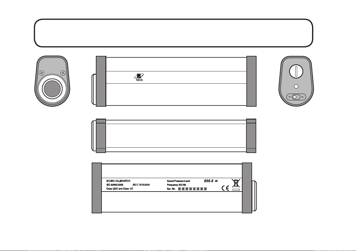
NC-72A Main Unit External View ............................................................... 2
Accessories External View........................................................................... 3
Names of Parts and Functions...................................................................... 5
Coupler ................................................................................................... 5
Power supply section............................................................................... 6
Side view and top view ........................................................................... 7
Operation ..................................................................................................... 8
Inserting the batteries ............................................................................. 8
Checking the battery voltage ................................................................ 10
Sound pressure measurement system (sound level meter) calibration .... 11
Using the microphone adapters ............................................................. 15
Reference ................................................................................................... 16
Output sound pressure level compensation............................................ 16
Electromagnetic Compatibility ............................................................. 26
Specications ............................................................................................. 29

1
Outline
The pistonphone NC-72A is a sound calibrator that conforms to IEC 60942:2003 (JIS C
1515:2004) class LS/C and class 1/C specications.
It uses a purely mechanical sound source with very low time-based variations which is
capable of producing a sound of constant pressure and frequency unaffected by envi-
ronmental changes (however, compensation of the output sound pressure level for static
[atmospheric] pressure changes is required). The NC-72A is suitable for use in research
institutions as calibration sound source for maintenance and management of acoustic
measurement systems.

2
NC-72A Main Unit External View
114dB
250Hz
PISTONPHONE NC-72A
### #
dB.
JIS C 1515:2004
IEC 60942:2003
SOUND CALIBRATOR
Class LS/C and Class 1/C
Sound Pressure Level
Frequency 250 Hz
Ser. No.

3
Accessories External View
N
C
-
7
2A
r
o
F
2
-
S
1
6
7
-
C
N
1/2-inch adapter
N
C
-
7
2A
r
o
F
2
-
S
0
6
7
-
C
N
1/4-inch adapter
R6P
LR6
R6P
LR6
R6PLR6
R6PLR6
R6PLR6
R6P
LR6
Six IEC LR6 (size AA) batteries
Barometer

4
Accessories External View
Carrying case Instruction manual (this document)
INSTRUCTION MANUAL
Pistonphone
NC-72A

5
Names of Parts and Functions
Coupler
Coupler Insert the microphone of the sound pressure measurement
system (sound level meter) here.
Use the 1/2-inch or 1/4-inch adapter as required to match
the microphone dimensions.
Coupler
Important
The coupler section also contains the piston part that generates sound pressure.
If a foreign object enters the coupler, correct sound pressure and frequency are
not assured.
•Never insert nger or any kind of stick into the coupler.
•Protect the coupler from any metallic or other foreign matter and from water,
oil, or any other kind of liquid.
•Protect the coupler from dust and other contamination.

6
Names of Parts and Functions
Power supply section
Battery compartment screw
Turn this screw to open the cover for battery replacement.
Battery voltage monitor (LED)
Enables to visually check the state of the batteries.
Power switch Turns the unit on and off.
ON
OFF
Power switch
Battery compartment screw
Battery voltage monitor (LED)

7
Names of Parts and Functions
Side view and top view
114dB
250Hz
### # dB.
JIS C 1515:2004
IEC 60942:2003
SOUND CALIBRATOR
Class LS/C and Class 1/C
Sound Pressure Level
Frequency 250 Hz
Ser. No.
Nominal sound pressure level
Nominal frequency
Sound pressure level indication
Serial number
(Specied sound pressure level at reference conditions)

8
Operation
Inserting the batteries
1. Remove the cover from the unit.
Insert a atblade screwdriver in the slot of the battery compartment screw and
turn it counterclockwise to remove the cover. Make sure not to turn the screw too
much to prevent it from coming off.
2. Insert six fresh IEC LR6 (size AA) batteries into the battery compartment, with
correct +, - orientation as shown on page 9. The label in the battery compartment
also indicates the polarity.
3. Press the cover against the unit and turn the battery compartment screw clockwise
with the atblade screwdriver until the screw is tight.
Cover
Battery compartment
Battery label
Six IEC LR6
(size AA) batteries
Screwdriver slot
Battery compartment screw
LR6 (R6P)
LR6 (R6P)

9
Operation
Important
- Make sure to insert batteries with correct +, - orientation as shown above.
(The label in the battery compartment also indicates the polarity.)
- A total of six batteries are required.
- Do not mix old and new batteries.
- Do not mix different battery types.
- To prevent the risk of battery uid leakage that can cause corrosion and dam-
age, be sure to remove the batteries from the unit when not using it.
- Dispose of used batteries in accordance with local laws and regulations.
- Do not charge or dismantle a battery, do not throw a battery into a re, and do
not short-circuit a battery. Otherwise uid leakage may occur or the battery
may explode.
R6PLR6
R6PLR6
R6PLR6
R6PLR6R6PLR6
R6P
LR6

10
Operation
Checking the battery voltage
The constant sound pressure generator in the unit uses an electronically controlled motor
to drive a piston and create an accurate sinusoidal wave. Frequency precision is within
±1% provided that the battery voltage is between 7 volts and 10 volts. The battery voltage
monitor (LED) allows the operator to check the state of the batteries, in order to assure
correct performance.
Unit cannot
be used
Lit
Battery voltage
normal
Flashing
Battery voltage low
(Unit can still be used)
Off
When turning power to the unit on, use the battery voltage monitor (LED)
to check the state of the batteries.
If the battery voltage monitor (LED) is off, the batteries must be replaced. If the battery
voltage monitor (LED) is ashing, the batteries will have to be replaced soon. For infor-
mation of how to replace the batteries, see pages 8 to 9.
Battery life at room temperature (approx. 23°C) is about 2 hours of continuous use with
manganese batteries (R6P) or about 13 hours of continuous use with alkaline batteries
(LR6).

11
Operation
Sound pressure measurement system (sound level meter) calibration
1. Verify that the power switch of the pistonphone is off.
2. Set the frequency weighting of the sound pressure measurement system (sound
level meter) to "Z" or "C".
3. Select the measurement range of the sound pressure measurement system (sound
level meter) so that 114 dB can be measured.
4. Carefully insert the microphone of the sound pressure measurement system (sound
level meter) fully into the coupler of the pistonphone.
Important
When inserting the microphone into the pistonphone, always
proceed very slowly and carefully, to avoid the possibility
of damage to the microphone diaphragm caused by abrupt
changes in air pressure.
Also, do not rotate the microphone or the pistonphone while
inserting. Otherwise the protective grid of the microphone
may become loose or detached, causing damage to the
microphone diaphragm.

12
Operation
5. After inserting the microphone into the pistonphone, wait at least 1 minute.
Note
If calibration is performed immediately after inserting the micro-
phone, correct results can not be achieved due to the change in air
pressure. You must wait about 1 minute until the pressure inside
the microphone stabilizes. The exact amount of required time is
vary depending on the microphone. Refer to the documentation of
the microphone or the sound pressure measurement system (sound
level meter) for more information.
6. When the indication of the sound pressure measurement system (sound level meter)
has stabilized, read the indicated value.
7. Turn the power to the pistonphone on.
Wait until the indication of the sound pressure measurement system (sound level
meter) has stabilized. Then read the indicated value. Verify that the value is at
least 30 dB higher than the value obtained in step 6.
Important
If the difference in readings is less than 30 dB, correct
calibration will not be possible, due to the influence of
background noise.
Table of contents