Ripley ODM DLS 350 Application guide
M-UM008-01 Page 1
DLS 350 Dual LED Source
Device Manual and Quick-Start Guide
The DLS 350 dual LED source is a multimode test LED used for verifying the proper function
of ber optic networks. This document will serve as an overview of the major features and
functions of the device and will oer tips for troubleshooting common issues in optical
networks.
12
4567
3
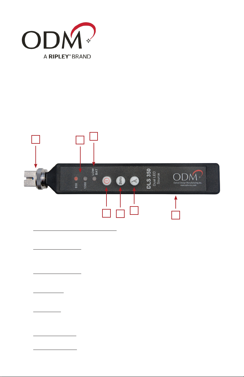
1. Connector Adapter - Interchangeable
The DLS 350 comes with an SC screw-on adapter. Additional adapters are available from ODM; see
page 4 of this document for more information.
2. Wavelength Indicator
This unit oers 850nm and 1300nm wavelengths. When the DLS 350 is turned on, the red
light indicates which wavelength is selected. The red light will blink to indicate when the 2kHz
modulation is turned ON.
3. Low Battery Indicator
A red indicator light will appear when the CR2 battery power is low. Replace the battery to return
to normal operation of the DLS 350.
4. Power Button
Press this button to turn the DLS 350 ON and OFF. The unit will turn o automatically after 15
minutes. To bypass the auto-shuto, hold the power button for 5 seconds when turning ON.
5. 2kHz Button
Toggles 2kHz modulation of currently-selected wavelength output. LED ashes at 2000 times per
second to provide a recognizable signal to a companion power meter. Output power of the LED is
reduced by 3dB when the modulation is active.
6. Wavelength Button
Switches between the 850nm and 1310nm wavelength.
7. External Power Port
Accepts AC 030 power supply. Power supply is not a battery charger, just battery bypass.
Device Overview

M-UM008-01 Page 2
The DLS 350 is calibrated to have an output power level of -22dBm. Variations in power
level between -22dBm and -25dBm may be normal depending on the quality and age of
the test jumper, the DLS 350 output port, and other factors.
Always ensure the DLS 350 is transmitting an acceptable power level before performing
an insertion loss test. Simply insert the test jumper (plugged into the DLS 350) into a
companion power meter set to the dBm mode. The power meter will indicate the measured
output power of the LED.
Transmitting Light
The DLS 350 transmits either the 850nm or 1300nm wavelength on singlemode ber. Be
sure to use a test jumper to mate the DLS 350 to the ber under test.
Test Jumper
Mate Connectors Appropriately
Signal Propagates Down Fiber
Caution: Invisible LED Radiation
Please note that 850nm and 1300nm wavelengths are not visible to the human eye. Do not
look directly into the output port of the DLS 350 or directly into any ber connector that
may be live.
Since the LED is invisible to the eye, the eye’s natural blink reex is suppressed. This can
cause damage to the retina.
FDA 21 CFR 1040.10 and 1040.11
IEC 60825-1: 2007-03
Class 1 LED Product
Output Power
Test Jumper Plugged
Into Power Meter Power Meter Displays
Output Power of LED

M-UM008-01 Page 3
Caring for the DLS 350 Output Port
Using the 2kHz Function
The DLS 350 utilizes a physical ber connection at the output port. This ensures a steady
power level for performing insertion loss tests.
Be aware that any test jumpers must be inspected and cleaned before plugging into the
DLS 350 unit. If soiled or damaged connectors are inserted, they can cause damage to the
DLS 350 output port and the unit may need to be repaired.
When the 2kHz modulation is active on the DLS 350, the currently-selected wavelength
indicator will blink. The 2kHz modulation will be recognized by optical power meters further
down the ber and indicated by a 2kHz notication onscreen and a loud beep.
The test jumper has
physical contact with the
ferrule inside the DLS 350.
To clean the ferrule
inside the DLS 350:
• Unplug the test jumper
• Unscrew the adapter until
it spins freely, then pull
• Inspect the ferrule with
an approved microscope,
clean if necessary, and
replace adapter

M-UM008-01 Page 4
Notes On Testing
AC 030 Battery Bypass
Singlemode bers usually have either blue (UPC) or green (APC) connectors. The DLS 350
LED source is made for multimode testing, so neither blue nor green connectors are
appropriate. Generally, multimode ber will have beige connectors.
DO NOT plug an APC connector into the DLS 350 unit. This can cause irreparable damage
to both connectors.
ODM oers the AC 030 wall plug for users who wish to leave their DLS 350 turned on for
long periods of time. This is NOT a charger, but rather powers the unit from a wall outlet.
Light Source Accessories
Light Source Adapters
Part Number Description
AC 022B SC Adapter
AC 023B FC Adapter
AC 024B ST Adapter
AC 025B LC Adapter
Patch Cord Accessories
Part Number Description
AC 550 MM SC-LC - 1m simplex
AC 551 MM SC-SC - 1m simplex
AC 552 MM LC-LC - 1m simplex
AC 600 SC-SC simplex bulkhead
AC 601 LC-LC simplex bulkhead
AC 602 LC-LC duplex bulkhead
Phone: 603-524-8350
Email: [email protected]
Web: www.odm-inc.com
Contact ODM Support
Other Ripley Diagnostic Equipment manuals


