iQube2 Junction Box/1280 Enterprise Quick Start Guide
2 Visit our website www.RiceLake.com
The iQube² must not be in an error condition when attempting to perform configuration. The iQube² will not take
a configuration if there are detected errors. You will need to clear all errors first. It is acceptable to hook up
simulators to help remove any existing error conditions. Errors can be related to any of the switches or wiring.
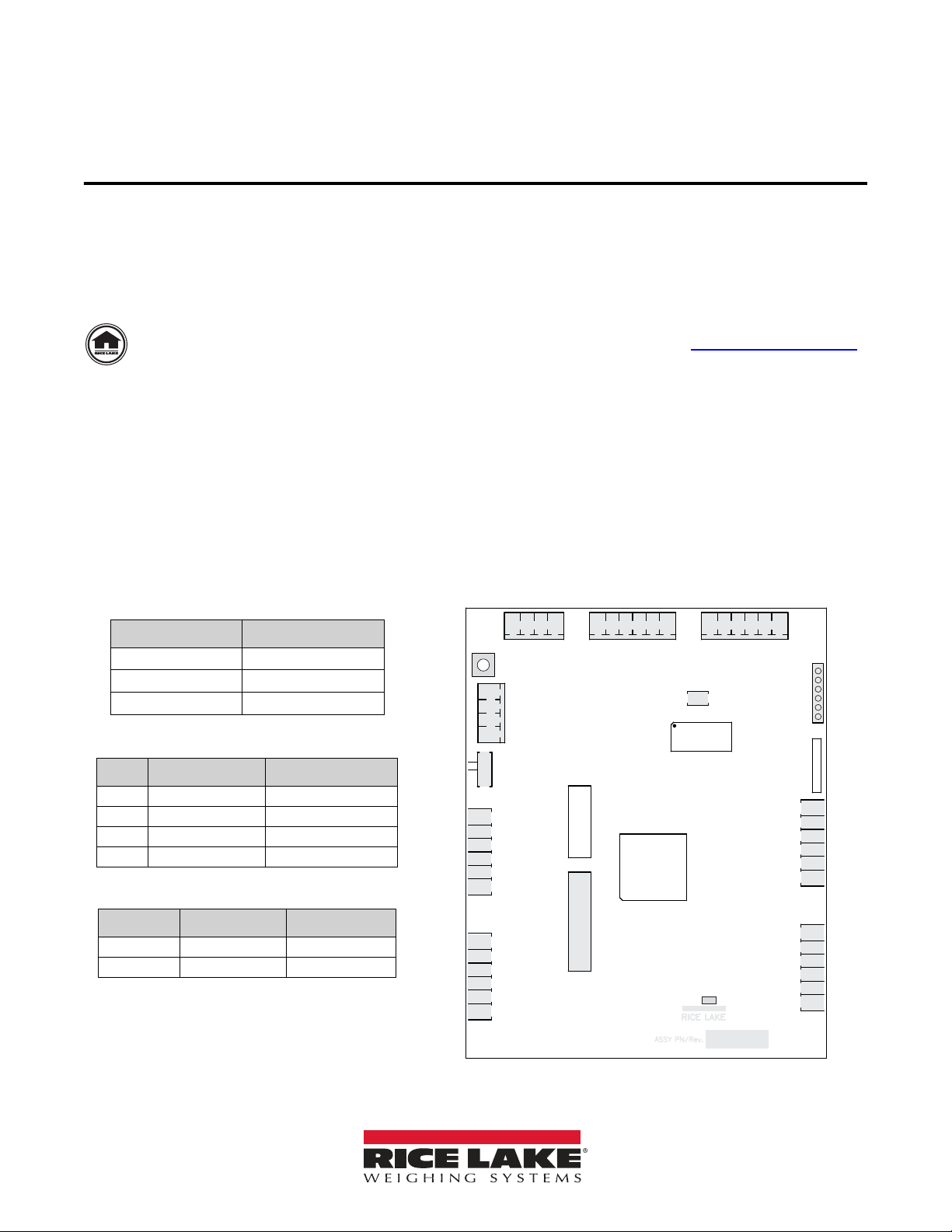
1.1.1 Switches
S1
The S1 is pressed to reset the iQube² to default factory settings (Section 1.1.2) and to assign board ID during Board setup
(Section 2.1 on page 7).
SW-1
When resetting iQube² to default settings or making changes to the iQube² unit, set SW-1 to CFG. For regular operation and
1280 communication, SW-1 must be switched to OFF.
S2
The S2 DIP switch reads only at Power-up.To allow iQube² to operate with RS-422 serial connection to 1280, switch both S2
DIP switches to Off. Double check that SW-1 is switched to CFG. Disconnect and reconnect power supply.
1.1.2 Reset iQube² to Default Factory Settings
Reset the iQube² to factory default settings to restart the configuration process. To return the iQube² unit to factory default
settings, switch SW-1 to CFG and hold down S1 switch until all lights turn red, then turn solid green.
1.1.3 Wire Load Cells
To avoid an error condition, all six load cell pins of all four connectors (J1-J4) must be connected to load cells. It is acceptable to
hook up simulators to help remove any existing error conditions. To attach load cell cables to the CPU board in Figure 1 on
page 1:
1. Route the cables through the cord grips on the load cell connector end of the enclosure.
2. Strip 1/4'' of insulation from the ends of the load cell wires.
3. Install wires into the connectors as shown in Table 4.
4. Use cable ties and mounts to secure the load cell cables to the enclosure, when connections are complete.
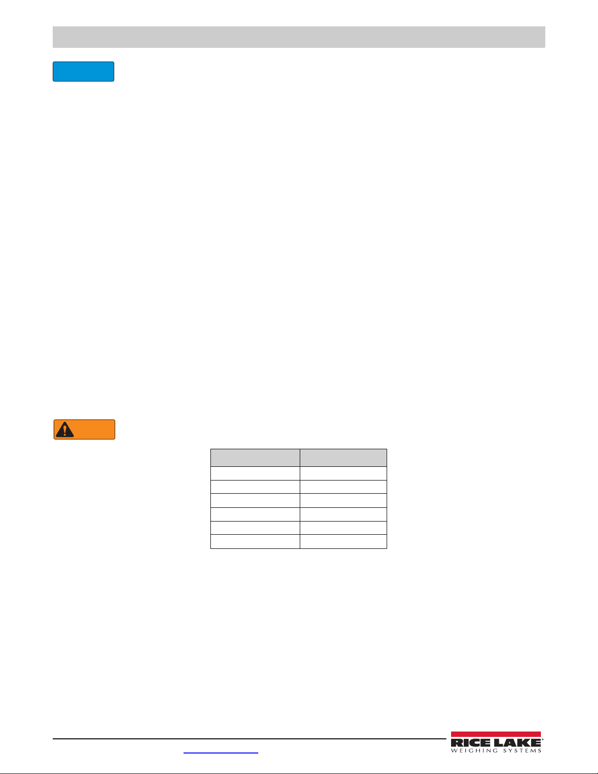
Pins 5 and 6 provide connections for load cells that provide TEDS (Transducer Electronic Data Sheet) information.
Do not connect sense wires to the TD terminals.
Pins Function
1 +SIG
2 –SIG
3 +EXC
4 –EXC
5 +TD (TEDS)
6 –TD (TEDS)
Table 4. Load Cell Connectors (J1-J4) Pin Assignments