- 1 -
Hauteur de montage et position selon la taille de la pièce :
Pour le 815DTG3
Hauteur de montage L - LONG C - COURT (SHORT)
Pour le 825DTG3
2.1m-2.7m (6'11"-8’10") 15m (50’) 6m (20’)
1.8m-2.0m (5'11"-6’7") 25m (82’) 8m (26’)
MIN MAX
E N G L I S H
The iWISE 815DTG3/825DTG3 detectors are the ultimate motion detectors for professional
installations, incorporating both Anti-Mask and Anti-Cloak™ Technologies (ACT™), adhering
to new environmentally friendly guidelines.
iWISE 815DTG3/825DTG3 detectors are available in 15m and 25m models, and include built-in
end-of-line (EOL) resistors to simplify installation.
* Grade 2 when installed with swivel
Installation / Maintenance
1. Mounting - The iWISE 815DTG3/825DTG3 can be mounted either on a flat surface or on a wall
corner (corner mounting).
•Using a suitable tool, open the following knockouts on the detector’s base (see Figure 1).
Note: If a back tamper is to be used it is mandatory to screw the tamper back plate to the wall
(or wall corner).
2. To select the correct vertical adjustment position for wide angle lens, use the scale on the bottom
left hand side of the PCB as follows:
Mounting height and scale position based on room size:
For 815DTG3
Mounting Height L - LONG S - SHORT
2.1m-2.7m (6'11"-8’10") 15m (50’) 6m (20’)
For 825DTG3
1.8m-2.0m (5'11"-6’7") 25m (82’) 8m (26’)
Note: For Corridor installations, select position to 'LONG' and mount the detector at 2.5m/8’2” height.
3. Set jumpers (see Jumper Setting section).
IMPORTANT: On the face of the Microwave, you will find a colored dot, this represents the Microwave
channel. When installing two detectors in near locations, it is recommended that these dots (channels)
are not of the same color. Example: Two Red should be avoided
Note: Reset the detector after each change made to the settings.
4. Install the front cover back to its place (in a reverse sequence of the removal.
5. Perform a Walk test (see Walk Test section).
6. Changing Lenses (see Figure 2).
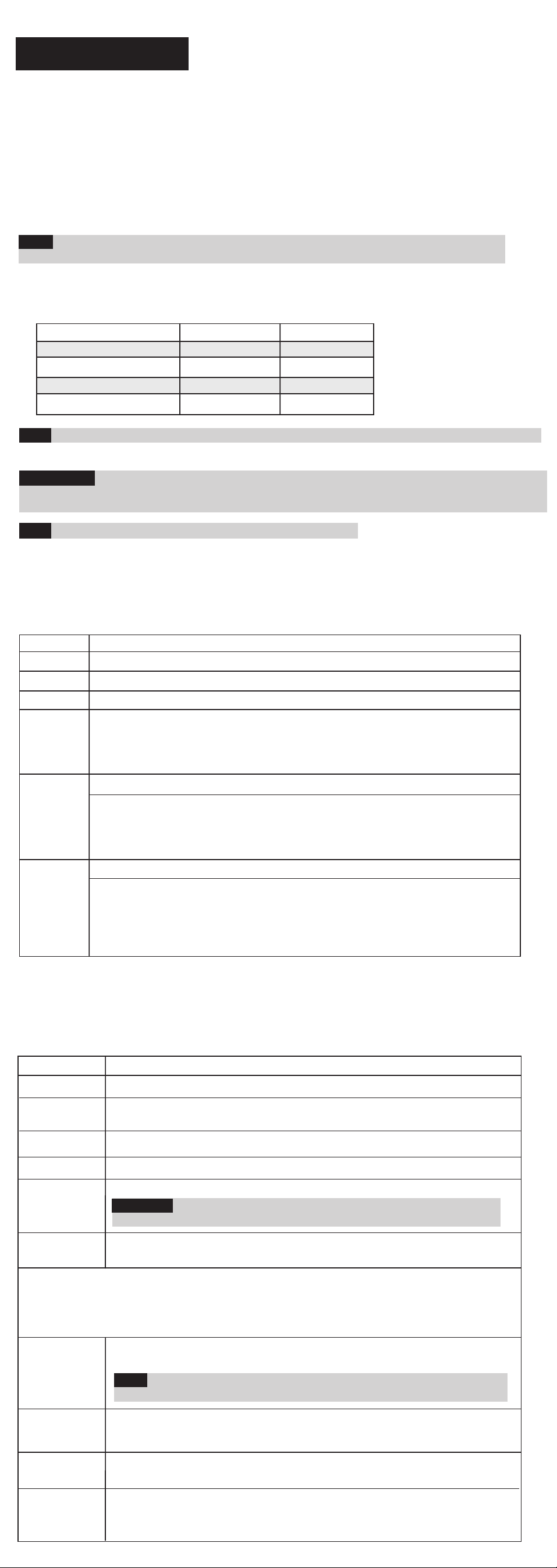
Terminal Wiring (see Figure 5)
Terminal Description
- 12 + 12VDC Input
ALARM N.C. Relay
TAMPER N.C. Tamper switch
FAULT/AM Normally Closed Relay: The FAULT/AM relay opens in the following events:
• Detector is masked (Alarm relay is also opened)
• Self test failed
• Input voltage is lower than 8VDC
LED LED operation remote control
When an ”Activation Signal”** is applied to the LED input terminal, all LEDs will
be disabled.
LEDs are enabled if nothing is connected (unless LED jumper is OFF) or 0V/12V
is applied (according to the LED/SET Input Jumper position, 12V or 0V).
SET Remote SET/UNSET control
SET:If an ”Activation Signal”** is applied, anti-mask detection is disabled (for
Grade 2 configuration).
UNSET: If nothing is connected or 0V/12V is applied (according to the LED/SET
Input Jumper position, 12V or 0V) anti-mask detection is enabled (see also
“Green Line” and “Remote Self Test”
**Activation Signal-
If 12VDC is applied, and the LED/SET Input Jumper is on 12v position
- Or -
0V is applied and LED/SET Input Jumper is on 0V position
Jumper Settings
Jumper Function
SW1-2: ACT
ON
ACT Enabled
Important: Do not use ACT™ mode if you are expecting that there will be
moving objects outside the required protected area, a corridor for example.
OFF ACT Disabled.
SW1-1: LED Used to determine the operation of the detector’s LEDs
Used to determine if ACT mode is enabled or disabled
ON: LEDs are enabled, allowing LED control via the LED input terminal
OFF: LEDs are disabled
Walk Test
1. Two minutes after applying power (warm-up period), walk test the Detector over the entire protected
area to verify proper operation of the unit (see Figure 6).
2. The MW range can be adjusted by using the potentiometer located on the PCB. It is important to set
the potentiometer to the lowest possible setting that will still provide enough coverage for the inner
boundary protected area (see Figure 4).
MW range adjustment (Figure 4)
1Over power ADetector
2Under power BCorridor
3Correct adjustment
LEDs Display
LED State Description
Yellow On PIR detection
Flashing Trouble in PIR channel
Green On MW detection
Flashing Trouble in MW channel
Red On ALARM
Flashing Fault / Anti-Masking detection
Note: Anti Masking detection is operational in “Unset” mode only
(see Terminal Wiring section, SET terminal).
All LEDs Flashing At power-up, the LEDs will flash consecutively until the end of the
warm-up period (2-3 minutes). At the end of the warm-up period
the RED LED will continue to flash until the end of AM initiation.
(consecutively)
Note: AM and Trouble indications continue until masking is removed or trouble is corrected.
Technical Specification
Electrical
Current consumption 16mA at 12VDC (Typical)
41mA at 12VDC (max.)
Voltage requirements 9 -16VDC***
Alarm contacts 24VDC, 0.1A
Tamper contacts 24VDC, 0.1A
FAULT/AM contacts 24VDC, 0.1A
Environmental
RF immunity According to EN50130-4
Operating temperature -10C to 55C (14F to 131F)
Storage temperature -20C to 60C (-4F to 140F)
Optical
Filtering White Light Protection
Physical
Size 127.6 x 64.2 x 46.6 mm (5 x 2.5 x 1.84 in.)
Weight
*** Power to be supplied by 5A max. power source using safety approved wires,
with a min Gauge of 20AWG.
120 gr. (4.2 oz.)
EN50131-1 Grade 3*
EN50131-2-4 Grade 3*
EN50131-6 Type C
EN50130-5 Class II
EN50130-4
F R A N Ç A I S
Les détecteurs iWISE 815DTG3/825DTG3 sont les tout derniers modèles de détecteurs de mouvement
conçus pour les établissements professionnels. Ils intègrent deux technologies de pointe: Anti-masque
et Anti-Cloak™ (ACT™) Anti-camouflage, qui répondant aux nouvelles directives de protection de
l'environnement et sont conformes aux exigences des normes PD6662, EN50131-1, EN50131-2-4
Grade 3, et de la norme NF&A2P Type 3.
Disponibles en modèles 15m et 25m, les détecteurs iWISE 815DTG3/825DTG3 comprennent des
résistances de Fin de ligne (EOL = end-of-line) intégrées qui facilitent l'installation.
Installation
1. Montage – l'iWISE 815DTG3/825DTG3 peut être installé soit sur une surface plane soit en coin
(gauche ou droit).
•
A l’aide d’un outil adequat, ouvrez les pastilles pr
é-
perc
ée
s correspondantes sur la báse du d
tecteur (cf. Figure 1).
Remarque: En cas d'utilisation d'une autoprotection arrière, il est impératif de fixer la plaque de cette
dernière en la vissant au mur (ou à l'angle du mur).
2. Pour définir le bon réglage vertical, positionnez l'appareil en LENTILLE GRAND ANGLE. Servez-vous
de l'échelle figurant sur le côté inférieur gauche de la carte PCB (cf. Figure 6) comme suit :
3. Réglez les cavaliers (cf. § Réglage des cavaliers).
Remarque: Il est conseillé de réinitialiser le détecteur après chaque modification apportée au réglage.
4. Replacez le couvercle frontal (en inversant pour cela l'ordre des étapes de la procédure de retrait).
5. Exécutez un test de passage (cf. § Test de passage).
6. Changement des lentilles (cf. Figure 2).
Câblage des Terminaux (cf. Figure 5)
Terminal Description
- 12 + Entrée 12VCC
ALARM Relais N.F., 24VCC, 0,1A
TAMPER Relais N.F., 24VCC, 0,1A
FAULT / AM Sortie normalement fermée : La sortie FAULT/AM s'ouvre dans les cas
suivants :
• Détection ou neutralisation d'un masquage,
• Echec du test automatique,
• Tension d'entrée inférieure à 8VCC.
LED Contrôle à distance des indicateurs LED
Lorsqu'un ”Signal d'Activation”** est appliqué à l'entrée LED du bloc des
terminaux ou bornes de connexion, les indicateurs LED se désactivent
(cf. aussi l'entrée Test automatique dans le tableau consacré au Réglage
des cavaliers).
Les voyants LED sont activés si rien n'est relié (sauf si le cavalier LED
est éteint (OFF).
SET Contrôle à distance de la mise en Service (SET) / mise en Inactivité du
système (UNSET).
SET (mise en service): Si un ”Signal d'Activation”** est appliqué, la
détection de masquage est désactivé (en configuration de catégorie 2).
UNSET (mise en inactivité) : Si aucune connexion n'est appliquée ou
que la Terre (GND/12V) est reliée (selon la position du Cavalier d'entrée
LED/SET, à 12V ou 0V), la détection de masquage est activée (cf.
également les entrées “Green Line” et “Test automatique à distance”
dans le tableau consacré au Réglage des cavaliers).
**Signal d'Activation-
Si une tension de 12VCC est appliquée et que le Cavalier d'entrée LED/SET est en position 12V
-Ou-
Si la Terre (GND) est reliée, le Cavalier d'entrée LED/SET est en position 0V.
Réglage des cavaliers
Cavalier Fonction
SW1-1: LED Définit le fonctionnement des indicateurs LED du détecteur.
Marche (ON) L'activation des indicateurs LED dépend du paramétrage du contrôle à distance
de leur fonctionnement (cf. § Câblage des Terminaux, borne de connexion LED).
SW1-4: Self
Test Used to test detection technologies.
(Local Self Test): If there is no alarm detection in the PIR channel fora period
of one 1 hour, the detector will self-test. If the local self test fails, the FAULT/AM
Relay will activate.
(Remote Self Test): Remote Self Test is activated when the SET terminal is
switched from SET to UNSET mode. For remote self test pass, the Alarm Relay
will activate for 5 seconds.
ON
OFF
Arrêt (OFF) Les indicateurs LED sont désactivés.
Définit si le mode ACT est activé ou non
SW1-4:
Test
automatique
Permet de tester la capacité de détection des canaux IRP et HF.
(Test automatique local): si aucune détection n'est décelée pendant une période
d'une heure, le détecteur exécute un test automatique. En cas d'échec du test
automatique local, le relais FAULT/AM est activé.
(Test automatique à distance): le test automatique à distance s'active lorsque le
terminal de réglage (SET) passe du mode de mise en service (SET) à celui
d'inactivité du système (UNSET).
Si le test automatique à distance réussit, le relais d'alarme s'active pendant 5
secondes. Si le test échoue, c'est le relais FAULT/AM qui s'active.
SW1-3: Green Line
L'iWISE 815DTG3/825DTG3, concept qui permet aux détecteurs de respecter les directives
environnementales en évitant les émissions excessives. Cette caractéristique permet en effet
de désactiver le canal HF (hyperfréquence) lorsque le système d'alarme est inactivé (“UNSET”),
neutralisant ainsi tout excès d’émission d’hyperfréquences pendant que les locaux sont occupés.
Marche (ON)
"Green Line" activée: Pour désactiver le module HF pendant les périodes
d'inactivité du système (UNSET), les indicateurs LED doivent aussi être
désactivés à distance.
Arrêt (OFF) Green Line désactivé (OFF): le canal HF est constamment activé.
Les cavaliers J1, J2 et J3 permettent de sélectionner les résistances EOL
(fin de ligne) d'Autoprotection, Alarme et FAULT/AM (1K, 2,2K, 4,7K, 5,6K,
6,8K et 12K) en fonction de la centrale (cf. Figure 3 ci-dessous).
Suivez les indications du diagramme de connexion du bloc des terminaux
de la Figure 3 pour relier le détecteur à une zone EOL Double/Triple
(DEOL/TEOL).
SW1-2: ACT
Marche (ON) ACT activé.
Important ! N'utilisez pas le mode ACT™ dans une zone en dehors de laquelle
le passage d'objets en mouvement vous paraît logique et attendu, un couloir par
exemple.
Arrêt (OFF) ACT désactivé.
(Défaut)
(Défaut)
(Défaut)
(Défaut)
(Default)
(Default)
(Default)
(Default)
Arrêt (OFF)
Cavaliers TEOL
Marche (ON)
J1 - Alarm EOL
J2 - Tamper EOL
J3 - FAULT / AM EOL
SW1-3: Green Line
The iWISE 815DTG3/825DTG3 includes a Green Line feature that follows environmental
guidelines by avoiding surplus emission. This feature disables the MW channel when the
alarm system is “Unset”, thus eliminating surplus MW emission while the premises is occupied.
ON Green Line feature is enabled: To deactivate the MW module in “UNSET”
period, the LEDs must also be remotely disabled by the LED terminal.
Note: When ‘Green Line’ is on (Microwave off), the detector will still activate
(PIR only)
OFF Green Line feature in disabled: MW is constantly in use.
iWISETM
Models: iWISE 815DTG3
iWISE 825DTG3
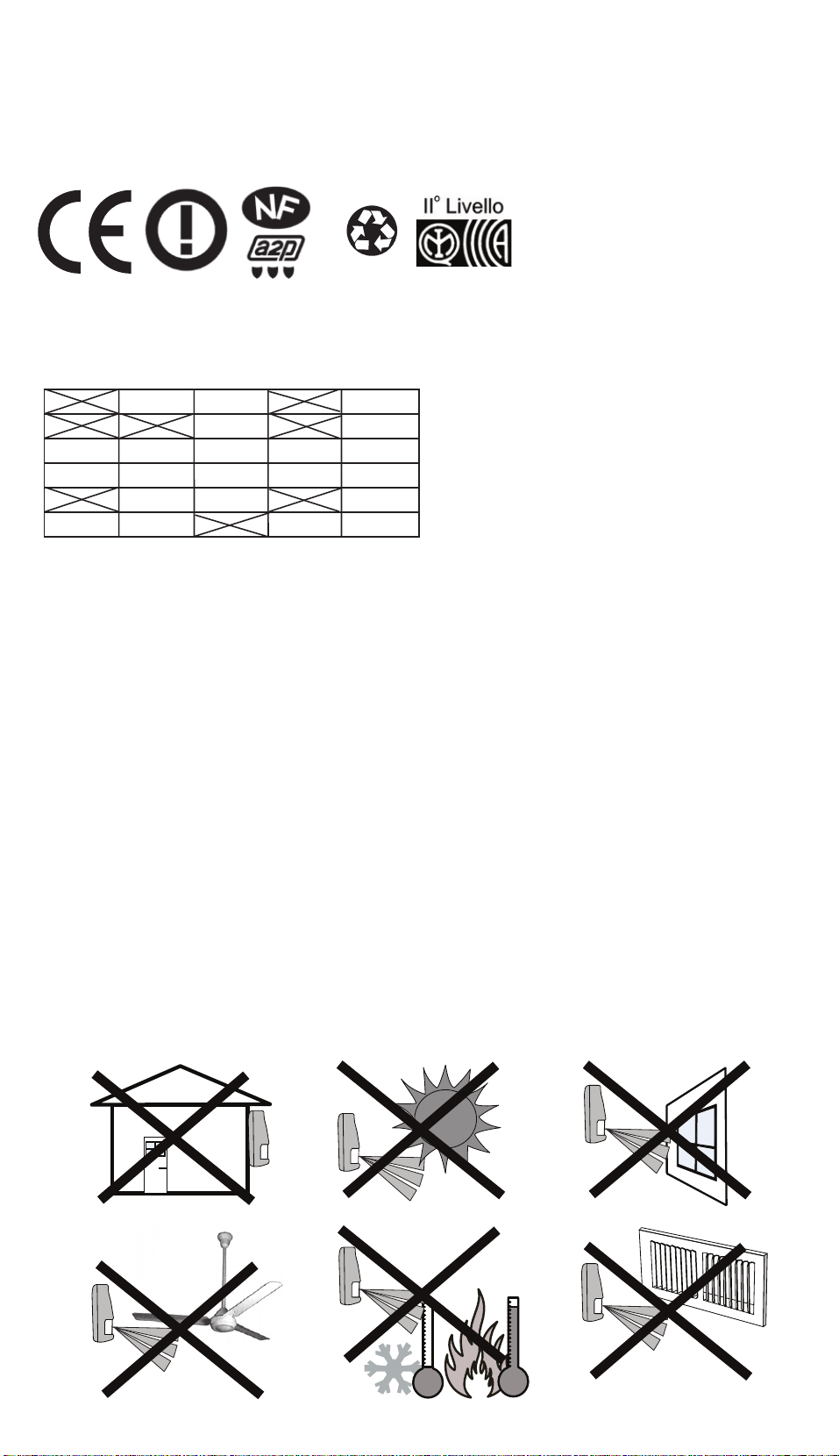
iWISE 815DTG3/825DTG3 applicable countries (European version):
AT BE CY CZ DK
EE FI FR DE GR
HU IE IT LV LT
PT
LU MT NL PL
SE SL ES SK GB
BG RO TR CH NO
CE Compliance Section (European and German versions):
Risco Ltd. hereby declares that this equipment is in compliance with the essential requirements
and other relevant provisions of Directive 1999/5/EC. For the CE Declaration of Conformity
please refer to our website: www.riscogroup.com
iWISE 815DTG3/825DTG3 applicable countries (German Version):
AT, CZ, SL, DE, TR, RU, EE
iWISE 815DTG3/825DTG3 FCC compliance Section (US version):
FCC Part 15 Note:
This equipment has been tested and found to comply with the limits for a Class B digital device, pursuant
to Part 15 of the FCC rules. These limits are designed to provide reasonable protection against harmful
interference in a residential installation. This equipment generates, uses and can radiate radio frequency
energy and, if not installed and used in accordance with the instructions, may cause harmful interference
to radio communications.
However, there is no guarantee that interference will not occur in a particular installation. If this
equipment does cause harmful interference to radio or television reception, which can be determined by
turning the equipment off and on, the user is encouraged to try to correct the interference by one or more
of the following measures:
• Reorient or relocate the receiving antenna.
• Increase the separation between the equipment and receiver.
• Connect the equipment to an outlet on a circuit different from that to which the receiver is connected.
• Consult the dealer or an experienced radio/TV technician.
FCC Warning:
The manufacturer is not responsible for any radio or TV interference caused by unauthorized
modifications to this equipment. Such modifications could void the user's authority to operate the
equipment.
FCC ID: JE4CSMDT
U.S. Patent Number:
This product is protected under Patent No. US 7,126,476 B2. Other patents pending.
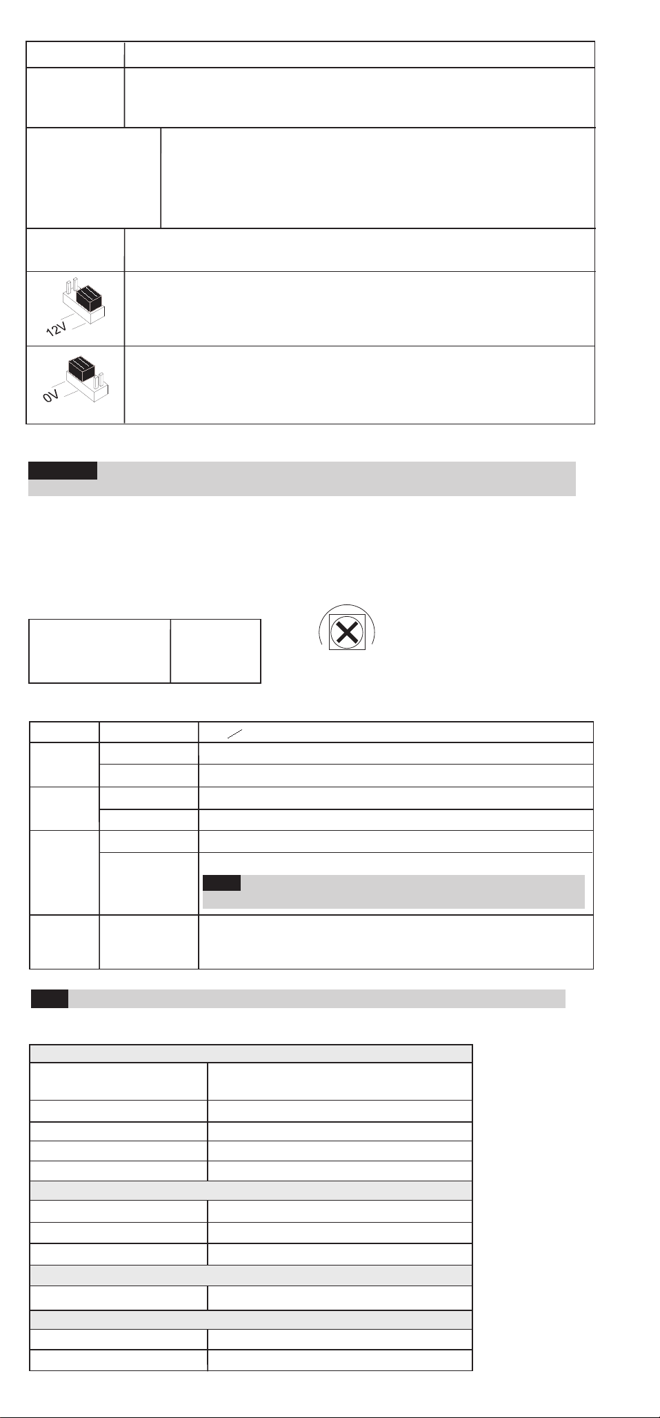
Jumper Function
J4 - LED/SET
INPUT Used to determine the polarity of the external input.
See Terminal Wiring section, LED and SET Terminals
See Terminal Wiring section, LED and SET Terminals
J1 - Alarm EOL
J2 - Tamper EOL
J3 - FAULT/AM EOL
Jumpers J1 and J2 allow the selection of Tamper and Alarm resistance
(1K, 2.2K, 4.7K, 5.6K, 6.8K) according to the control panel (see Figure 3).
Jumper J3 allows the selection of 12K for Fault/Anti-Mask.
Follow the terminal block connection diagram in Figure 3 when
connecting the detector to a Double/Triple End Of Line (DEOL/TEOL)
Zone.
Important: After applying power to the detector, close the cover within 2 minutes as after this
period AM initialization will start.
Remarque: Pour les installations en couloir, sélectionnez la position 'LONG' et appliquez l'option de
montage à hauteur de 2,5m/8’2”.
5IN1235 08.2009
Ce produit répond aux exigences du référentiel de certification NF324-H58
Type 3 (selon les référentiels NF 324 H58, NF C 48-225 et NF C 48-435).
MIN MAX
Test de passage
1. Deux minutes après avoir réalisé la mise sous tension (séquence d'échauffement), effectuez un
test de passage pour vérifier l'efficacité du détecteur sur la totalité de la zone à protéger.
2. Assurez-vous d'avoir bien réinstallé le couvercle frontal avant de mettre le détecteur sous tension
(cf. Figure 6).
3. Le potentiomètre situé sur la carte PCB permet de régler la portée de détection hyperfréquence. Il
est important de régler le potentiomètre sur le niveau le plus bas possible qui fournira cependant
une couverture suffisante sur la totalité de la zone à protéger.
Réglage de la portée HF (cf. Figure 4)
1Trop puissant
2Pas assez puissant
3Réglage correct
ADétecteur
BCouloir
Affichage LED
LED Position Signification
Jaune Allumée (ON) Détection IRP
Clignotante Panne de canal IRP
Verte Allumée (ON) Détection HF (hyperfréquence)
Clignotante Panne de canal HF
Rouge Allumée (ON) Indique une ALARME
Clignotante Détection d'Erreur /Anti-masque
Remarque: La détection Anti-masque est opérationnelle
en mode “UNSET” (Inactivité du système) seulement (cf.
§ Câblage des Terminaux, terminal de mise en service
(SET).
Toutes
diodes LED Clignotante Lors de la mise sous tension, les diodes LED clignotent de
manière ininterrompue, l'une après l'autre, jusqu'à la fin de
la séquence d'échauffement (2 à 3 minutes). A la fin de ce
laps de temps, le voyant LED ROUGE continue à clignoter
jusqu'à la fin du lancement de l'AM (pour mettre un terme
au clignotement, fermez le couvercle).
(l'une après
l'autre)
Remarque: Les indications AM et Panne persistent jusqu'à élimination de la cause du masquage
ou réparation de la panne.
Spécifications techniques
Consommation électrique 14.8 mA à 12VCC (en utilisation typique)
39.5 mA à 12VCC (max. avec tous les voyants
LED allumés)
Tension requise 9 -16VCC
Contacts d'alarme 24VCC, 0,1A
Temps minimal de changement d’état: 2.2 seconds
Contacts d'autoprotection 24VCC, 0,1A
Contacts FAULT/AM 24VCC, 0,1A
Rétsistance de la boucle de Détection: Etat ouvert: plus que 108
Etat fermé: moins que 1 ohm
Ondulations résiduelles maximales
admissibles: 0.25 créte à créte
Taille du càble à utiliser: Fil de diamétre au moins 0.5 mm pour une
longueur ne dépassant pas 300 métres
Optiques
Filtrage Protection anti-lumière blanche
Physiques
Dimensions 127.6 x 64.2 x 46.6 mm (5 x2.5 x 1.84 in.)
Poids 120g
Organisme de certification
Environnementales
Immunité RF Selon EN50130-4
Température de fonctionnement De -20ºC à 55ºC (-4ºF à 131ºF)
Température de stockage De -20ºC à 60ºC (-4ºF à 140ºF)
Indice de protection: IP 31/IK 02
Electriques
Important : Après la mise sous tension du détecteur, fermer le couvercle dans les 2 minutes
pour que la période d’initialisation AM (Anti-Masque) démarre.
Nederlands
De detectors iWISE 815DTG/825DTG3 zijn de ultieme bewegingsdetectors voor professionele
installaties die met de Anti-maskering- en Anti-Cloak™-technologieën samenwerken (ACT™). Hierbij
stellen zij zich in op nieuwe omgevingsvriendelijke richtlijnen.
iWISE 815DTG3/825DTG3-detectors zijn beschikbaar in modellen van 15 m en 25 m, en bevatten
ingebouwde eind-van-lijn-weerstand (EOL) om de installatie te vereenvoudigen.
Installatie / Onderhoud
1. Montage - De iWISE 815DTG3/825DTG3 kan op een vlakke oppervlakte worden gemonteerd, of op
een muurhoek (hoekmontage)
• Met een passend gereedschap opent u de volgende uitwerpers op de basis van de detector (zie
Afbeelding 1).
Opmerking: Als een achterstamper wordt gebruikt, is het verplicht om de achterplaat van de stamper
op de muur (of muurhoek) vast te schroeven
2. Om voor de brede hoeklens de juiste verticale afstelpositie te selecteren, gebruikt u de schaal op de
linker onderkant van de PCB. U doet dit als volgt:
Montagehoogte en schaalpositie op basis van kamergrootte:
Voor 815DTG3
Montagehoogte L - LANG C - KORT
2.1m-2.7m 15m 6m
Voor 825DTG3
1.8m-2.0m 25m 8m
Opmerking: Voor installaties in een hal selecteert u de positie naar 'LANG' en monteert u de detector
op een hoogte van 2,5 m/8'2".
3. Jumpers instellen (zie sectie Jumperinstellingen).
Opmerking: Stel na elke wijziging aan de instellingen, de detector opnieuw in.
4. Installeer het voorste lid terug op zijn plaats (in omgekeerde volgorde van de verwijdering).
5. Voer een looptest uit (zie sectie Looptest).
6. Lenzen wisselen (zie. Afbeelding 2).
Bedrading terminal (zie Afbeelding 5)
Terminal Beschrijving
- 12 + 12 VDC-ingang
ALARME N.C.-relais
TAMPER N.C. Sabotageschakelaar
FAULT/AM Normaal gesloten relais: De relais STORING/AM wordt bij de volgende
gebeurtenissen geopend:
• Detectorbewaking wordt ingeschakeld (Relais alarm wordt ook geopend)
• Zelf-test is mislukt
• Ingangspanning is lager dan 8VDC
LED LED-werking afstandsbediening
Als op de LED van de ingangterminal een "Activeringsignaal"** wordt toegepast,
worden alle LED's uitgeschakeld. LED's worden ingeschakeld als niks is
aangesloten (tenzij LED-jumper op UIT is ingesteld) of 0V/12V wordt toegepast
(volgens de LED/INSTELLING positie van de ingangjumper, 12 V of 0 V).
SET Externe besturing INSTELLEN/NIET INSTELLEN
INSTELLEN: als een "activeringsignaal"** wordt toegepast, wordt de anti-
maskeringdetectie uitgeschakeld (voor configuratie Klasse 2).
NIET INSTELLEN: Als niks is aangesloten of als 0 V/12 V wordt toegepast
(volgens de LED/INSTELLING
Als 12 VDC wordt toegepast en de ingangjumper LED/INSTELLEN is op de positie 12V
-Of-
0 V wordt toegepast en ingangjumper LED/INSTELLEN is op positie 0 V
**Activeringsignaal-
Jumperinstellingen
Jumper Functie
SW1-2: ACT Gebruikt om vast te stellen of de ACT-modus is in- of uitgeschakeld.
AAN ACT ingeschakeld
Belangrijk: Niet de ACT™-modus gebruiken als u verwacht dat er buiten het
beschermde gebied (zoals bijvoorbeeld een hal, bewegende objecten zijn.
UIT ACT uitgeschakeld.
(Standaard)
(Standaard)
SW1-1: LED Gebruikt om de werking van de LED's van de detector vast te stellen.
AAN LED's worden ingeschakeld zodat via de ingangsterminal van de LED,
LED-besturing mogelijk is.
UIT LED's worden uitgeschakeld
SW1-4: Zelf
Test Gebruikt om detectietechnologieën te testen.
(Lokale zelftest): als in het PIR-kanaal gedurende 1 uur geen alarmdetectie
plaatsvindt, voert de detector een zelftest uit. Als de lokale zelftest mislukt,
wordt de STORING/AM-relais actief.
(Externe zelftest): de externe zelftest wordt geactiveerd als de terminal
INSTELLEN van de modus INSTELLEN naar NIET INSTELLEN schakelt.
Opdat de externe zelftest slaagt, zal de alarm-relais gedurende 5 seconden
actief zijn.
SW1-3: Groene lijn
De iWISE 815DTG3/825DTG3 bevat de functie Groene lijn die milieurichtlijnen volgt door een
overschot uitstraling te vermijden. Deze functie schakelt het MW-kanaal uit als het alarmsysteem
op "Niet instellen" is ingesteld en dus de overmatige MW-uitstraling wordt verwijderd terwijl het
gebied bezet is.
AAN Functie Groene lijn is ingeschakeld: om de MW-module in de periode "NIET
INSTELLEN" te deactiveren, moeten ook de LED's van een afstand door de
LED-terminal worden uitgeschakeld.
Opmerking: Als 'Groene lijn' aan is (microgolf uit), is de detector nog steeds
actief (alleen PIR).
UIT
AAN
UIT
Functie Groene lijn is uitgeschakeld: MW is constant in gebruik.
Jumpers J1 en J2 maken de selectie mogelijk voor sabotage- en
alarmweerstand (1K, 2.2K, 4.7K, 5.6K, 6.8K) volgens het bedieningspaneel
(zie Afbeelding 3). Met jumper J3 is de selectie mogelijk van 12K voor
Storing/Anti-maskering.
Volg het aansluitingsschema van het aansluitblok in Afbeelding 3 als u de
detector op een twee-/drievoudige zone aan het einde van de lijn
(DEOL/TEOL) aansluit.
(Standaard)
(Standaard)
J1 - Alarm EOL
J2 - Sabotage EOL
J3 - STORING/
AM EOL
Looptest
Belangrijk: Na voeding naar de detector toe te passen, sluit u het lid binnen 2 minuten. Na deze
periode start namelijk de AM-initialisatie.
1. Twee minuten na het toepassen van voeding (opwarmingsperiode), voert u over het hele beschermde
gebied van de detector de looptest uit om goede werking van de eenheid te verifiëren (zie Afbeelding 6).
2. Het MW-bereik kan worden afgesteld door de potentiometer op de PCB te gebruiken. Het is belangrijk
dat de potentiometer op de laagst mogelijke instelling wordt ingesteld om het binnenste beschermde
grensgebied voldoende dekking te bieden (zie Afbeelding 4).
Jumper Functie
J4 - LED/
INSTELLEN
INGANG
Gebruikt om de polariteit van de externe ingang vast te stellen.
Zie de sectie Bedrading terminal, terminals LED en INSTELLEN
Zie de sectie Bedrading terminal, terminals LED en INSTELLEN
- 2 -
MIN MAX
Afstelling MW-bereik (zie Afbeelding 4)
1Overspanning
2Onderspanning
3Juiste afstelling
ADetector
BHal
Groen Aan MW-detectie
Knipperen Storing in MW-kanaal
Rood Aan ALARM
Knipperen Storings-/anti-maskeringsdetectie
Opmerking: Anti-maskeringsdetectie is alleen in de
modus "Niet instellen" werkzaam (zie sectie Bedrading
terminal, terminal INSTELLEN).
Alle LED's Knipperen Opwarmingsperiode (2-3 minuten). Aan het einde
van de opwarmingsperiode gaat de RODE LED door
met knipperen tot het einde van de AM-initiatie.
(achtereenvolgende)
Opmerking: AM- en Storingsindicaties gaan door totdat de maskering wordt verwijderd of de
storing wordt gecorrigeerd.
Technische specificaties
Elektrisch
Stroomverbruik 16mA bij 12VDC (typisch)
41mA bij 12VDC (max.)
Spanningsvereisten 9 -16VDC
Alarmcontacten 24VDC, 0,1A
Sabotagecontactencontacten 24VDC, 0,1A
STORING/AM-contacten 24VDC, 0,1A
Omgeving
RF-immuniteit Volgens EN50130-4
Bedrijfstemperatuur -10C tot 55C
Opslagtemperatuur -20C tot 60C
Optisch
Filtrering Wit licht-bescherming
Fysiek
Grootte 127,6 x 64,2 x 46,6 mm
Gewicht 120 gr.
Display LED's
LED Status Beschrijving
Geel Aan PIR-detectie
Knipperen Storing in PIR-kanaal
ITALIAN O
I rivelatori iWISE 825DTG3/825DTG3 sono rivelatori di movimento che integrano le tecnologie più
avanzate per le installazioni professionali. Questi rivelatori includono sia la tecnologia Anti-Mask
che quella Anti-Cloak™ (ACT™).
iWISE 815DTG3/825DTG3 è disponibile nei modelli 15 e 25 metri ed ha le resistenze di fine linea
integrate nel circuito per semplificarne al massimo l’installazione.
Installazione / Manutenzione
1. Installazione - iWISE 815DTG3/825DTG3 può essere installato sia su di una superficie piana che
ad angolo.
• Utilizzando uno strumento appropriato aprire i fori a sfondare, di seguito elencati, della base del
contenitore come illustrato in Figura 1.
Nota: Se viene utilizzato il tamper antirimozione è obbligatorio avvitare al muro (o angolarmente al
muro) la linguetta del tamper antirimozione. Utillizzando il tamper antirimozione viene garantito il llº livello
di prestazione IMQ.
2. Per selezionare la posizione corretta della scheda elettronica con la lente grandangolo montata, usare i
riferimenti ( LONG / SHORT) situati nella parte inferiore sinistra della scheda elettronica seguendo le
indicazioni della tabella di seguito illustrata:
Altezza di installazione e regolazione scheda elettronica in funzione dell’area di copertura:
Per il modello 815DTG3
Altezza di installazione L - LONG S - SHORT
2.1m - 2.7m 15m 6m
Per il modello 825DTG3
1.8m - 2.0m 25m 8m
Nota: Per installazioni con Lente Corridoio selezionare sempre la posizione “LONG” e montare il
rivelatore a 2.5m di altezza.
3. Predisporre i ponticelli e i microinterruttori (Vedere la sezione relativa).
Nota: Ad ogni modifica delle predisposizioni/regolazioni, effettuare sempre un reset del rivelatore
rimuovendo e applicando tensione.
4. Rimontare il coperchio frontale e stringere la vite di blocco coperchio.
5. Effettuare una prova di copertura (Sezione Prova di movimento).
6. Sostituzione delle Lenti (vedere Figura 2).
Cablaggio Morsettiera (vedere Figura 5)
Morsetto Descrizione
- 12 + Ingresso di alimentazione 12V
ALARM Relé N.C.
TAMPER Interruttore N.C.
FAULT/AM Relé N.C.: Il relé FAULT/AM si attiva per gli eventi seguenti:
Il rivelatore è mascherato (anche il relé di allarme viene attivato)
L’auto-test del sensore è fallito
L’ingresso di alimentazione è minore di 8V
LED Controllo remoto dei LED e funzione GREEN LINE (con microinterruttore ponticello
GREEN LINE ON)
Quando viene applicato un ”Segnale di Attivazione”** al morsetto LED, tutti i LED
vengono disabilitati e, se il microinterruttore GREEN LINE è in OFF, la sezione
microonda viene disabilitata.
Nota: affinché la microonda venga disabilitata non ci deve essere alcun comando
sul morsetto SET.
I LED sono abilitati se al morsetto LED non è collegato niente (a meno che il ponticello
LED sia estratto).
SET Controllo remoto dello stato impianto
Stato Inserito: Quando viene applicato un ”Segnale di Attivazione”** a questo
morsetto, il circuito di Anti-Mask viene disabilitato (conforme alla normativa IMQ 2º
livello).
Stato Disinserito: Se all’ingresso non viene collegato niente il circuito Anti-Mask è
abilitato (vedere anche la tabella di predisposizione ponticelli e microinterruttori riferita
alla funzione “Green Line” e “Auto-test Sensore”.
**Per Segnale di attivazione si intende quanto segue-
- Viene applicata una tensione 12 Vcc e il ponticello LED/SET Input è nella posizione 12v
- Viene applicato un riferimento di alimentazione 0V e il ponticello LED/SET Input è nella posizione 0V
SW1-4: Self
Test Usato per testare le tecnologie di rilevazione.
(Auto-test locale): Se non viene rilevata alcuna attivazione del canale PIR per
1 ora, il rivelatore eseguirà un auto-test. Se il test fallisce, l’uscita a relé
FAULT/AM verrà attivata.
(Auto-test remoto): L’Auto-test remoto si attiva quando il morsetto SET viene
portato dalla condizione di Impianto INSERITO (Comando di attivazione
applicato) alla condizione di impianto DISINSERITO (nessuna tensione
applicata). A conferma che l’auto-test remoto è stato superato l’uscita a relé di
allarme si attiverà per 5 secondi. Nel caso in cui l’auto-test sia fallito si attiverà
l’uscita a relé FAULT/AM.
SW1-3: Green Line
iWISE 815DTG3/825DTG3 include la funzione Green Line che evita emissioni radio superflue
nell’ambiente. Questa funzione disabilita il canale a microonda (MW) quando il sistema di
sicurezza è disinserito.
La funzione Green Line è abilitata: Per disabilitare la sezione microonda (MW)
a sistema DISINSERITO va applicato un comando di attivazione al morsetto
LED (0V o 12V in funzione della polarità configurata tramite il ponticello
LED/SET INPUT). Anche i LED verranno in questo caso disabilitati. La sezione
microonda viene disabilitata in questo modo solo se al morsetto SET non viene
applicata alcuna tensione.
Nota: Quando la funzione Green Line è attiva (Microonda spenta), il rivelatore
si attiva usando la sola sezione ad infrarossi (PIR).
La funzione Green Line è disabilitata. La sezione a microonda (MW) è sempre
accesa.
Ponticelli Per
resistenze EOL
I ponticelli J1 e J2 permettono la selezione dei valori resistivi da assegnare
ai circuiti di Tamper e di Allarme (1K, 2.2K, 4.7K, 5.6K, 6.8K) in funzione
della centrale d’allarme utilizzata (vedere la Figura 3 in basso). Il ponticello
J3 inoltre, permette la selezione di una resistenza di 12K per supervisionare
il circuito Anomalia/Anti-Mask.
Seguire lo schema di collegamento dei morsetti illustrato in Figura 3 quando
si vuole collegare il sensore ad una centrale d’allarme usando il doppio o il
triplo bilanciamento resistivo (DEOL/TEOL).
Predisposizione microinterruttori e ponticelli
Microint./Pontic. Funzione
SW1-2: ACT Usato per abilitare o disabilitare la funzione ACT
ACT abilitato
Importante: Non usare la funzione ACT™ se nel luogo di installazione del
rivelatore si prevede movimento di oggetti al di fuori dell’area protetta come,
ad esempio, il movimento di persone in un corridoio attiguo.
ACT disabilitato.
(Default)
(Default)
(Default)
(Default)
SW1-1: LEDS Usato per abilitare o disabilitare il funzionamento dei LED.
ON I LED sono abilitati ed è possibile anche controllarli via comando remoto
tramite l’ingresso LED.
OFF
ON
OFF
ON
OFF
ON
OFF
I LED sono disabilitati. Non è possibile alcun controllo remoto.
J1 - Alarm EOL
J2 - Tamper EOL
J3 - FAULT/AM EOL
Cavalier Fonction
J4 - Entrée
LED/SET Détermine la polarité de l'entrée externe.
Cf. § Câblage des Terminaux, bornes de connexion LED et SET (Mise en
service).
Cf. § Câblage des Terminaux, bornes de connexion LED et SET (Mise en
service).
AFNOR CERTIFICATION: 11 rue Francis de Pressensé
93571 LA PLAINE SAINT-DENIS Cedex, http://www.marque-nf.com
CNPP: BP 2265, 27950 ST MARCEL, http://www.cnpp.com