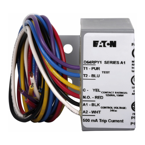
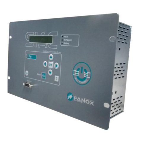
Rishabh Current Protection Relay Specification sheet

Current Protection Relay Operating Manual and Installation guide
Input connectors are marked by numbers 1, 2, 3, 4, 5, 6 and potential free
relay contacts are marked as 11, 12, 14 for relay1 and 21, 22, 24 for
relay2.Rated switchgear and fusing is required to prevent inrush. Wire of
2 sq. mm with Lug is recommended for Input connection. Use suitable
screw driver so that sufficient force can be applied, excess force may
result in damage to inside circuitry. Control voltage is to be applied with
fusing to the connector numbered as 14, 24. Refer diagrams for input
connection.
Connector details:
Parameter Settings:
Overcurrent Trip point 30 - 140 % of In
Undercurrent Trip point 10 - 95 % of In
Hysteresis Undercurrent , Overcurrent 5 - 50 % of trip point
Power on delay 3 Second Approx.
Reset delay 1 Second
Trip delay 0-10 Second (Undercurrent, Overcurrent)
Current unbalance Trip Point 20 % fixed
Current unbalance Trip Delay 5 Seconds fixed
Current unbalance Hysteresis 5 %
Safety IEC 61010-1-2010 Permanently
Operating reference condition
Reference Condition 23°C +/- 2°C
Input waveform Sinusoidal (distortion factor 0.005)
Input frequency 50 or 60 Hz + 2%
Technical Specifications:
Accuracy
Applicable Standards
Installation category: CAT III
IP for water & dust IEC60529
Pollution degree: 2
High Voltage Test 2.2 kV AC, 50Hz for 1 minute between
1 to 5 Amps settable
Nominal Input current In ( AC )
Auxiliary supply range 60-300 V AC/DC
all electrical circuits
Dimensions 53 x 110 x 60 mm
Contact Ratings 5A/250VAC/30VDC (resistive load)
Mechanical Endurance 1x10^7 OPS
Mechanical Attributes
Weight 175g Approx.
Electrical Endurance 1x10^5 OPS
Maximum continuous Input current (AC)
145 % of In
Current overload withstand
20 x for 1 second, repeated 5 Times in
5 minutes
Auxiliary nominal value 230 VAC 50/60 Hz
Auxiliary supply frequency 45 - 66 Hz
Operating measuring current range 5 to 140 % of nominal value
Operating measuring frequency range 40...70 Hz
Input current burden < 0.25 VA per phase at nominal
Auxiliary supply burden < 3 VA
Auxiliary supply voltage Nominal value + 1 %
Auxiliary supply frequency Nominal value + 1%
Measurement accuracy + 2 % of nominal value
Setting accuracy + 6 % of nominal value
+ 0.8 second for trip delay
Response time < 140 milisecond
Environmental
Operating temperature -10 to +55°C
Storage temperature -25 to +70°C
Relative humidity 0...90% non condensing
Shock 15g in 3 planes
Vibration 10...55 Hz, 0.15mm amplitude
Enclosure Flame retardant, IP20 (front face only)
Relay Contacts
connected use.
Types of output 1CO, 1CO+1CO
Relay configuration Energised or DeEnergised
(Energised-Relay is ON under healthy
condition and DeEnergised-Relay is
OFF under healthy condition)
Connection diagram:
3Phase
L1
N
L3
L2
123456
L
D
A
O
I1 I2 I3
7
8
L(+)
N(-)
AUX
SUPPLY
1Phase
L
N
12
L
D
A
O
I1
14
12 11
Relay 1
COM
NC NO
24
22 21
Relay 2
COM
NC NO
Installation:
Installation to be carried out by qualified person along
with life protecting equipment to prevent hazardous shock.
Isolate incoming supply before connection.
Do not expose device to Rain, Dust environment.
Keep at least 10-15 mm distance on both sides of device.
Do not install near Vibrating environment.
Do not install near Heat source.
Install Fuses of 2 Amp in series with supply.
Use Sealing provision to protect from unintentional
adjustment.
Dimensions and Terminals:
Mounting:
To mount the device it should be fastened to a standard 35mm DIN rail
(DIN50022).
To remove from DIN rail use screw driver to pullout clip as shown below.
Removing From DIN rail
Mounting On DIN rail
60.0 + 0.10
53.0
110.0
13.8
5.7
12 3 4 56
78911 12 14 21 22 24
5.7
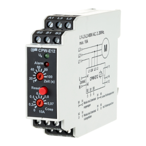
The Current Protection Relay protects system
from the current faults. Relay protects against
undercurrent, over current and unbalance
faults.
Multiple LEDs indicate type of fault that helps
for diagnosis purpose.
Switch (Key) is provided to enable/ disable
unbalance function and to select automatic /
manual resetting of faults upon fault recovery.
Manual reset ensures safety.
Potential free relay contacts can be used for
connection / disconnection of load or trigger
alarm for annunciation purpose.
relay configuration can be ordered in fail safe
and normal operation depending upon
application The application includes motor
protection, conveyor system and for process
industry, etc.

Tripping Test : Pass
Test Certificate:
Model : Current Protection Relay
Accuracy Test : Pass
Relay Test : Pass
Adjustment Test : Pass
De-Energised
Energised
Relay States -
Pd - Power ON Delay
Td - Trip Delay
Rd - Reset Delay
I1
I2
I3
OC
UC
Hysteresis
Pd
Relay 1
In
Relay 2
&
Hysteresis
Td Td
Rd Rd
5sec
Rd
> 20% of In < (20% of In
-Hysteresis)
Over Current Under Current UnBalance
Current (A)
Time (sec)
Figure : Tripping functionality for 3 Phase System with default Energised Relay
I1 I3
I2
Td
Overcurrent
Undercurrent
Tripping Diagrams:
Rishabh Instruments PVT. LTD.
Trishala Unit , C-6 , NICE Area , MIDC Satpur,Nasik-422007 , India
Tel : +912532202371/028 Fax:+912532351064 , Email : [email protected] , www.rishabh.co.in DMAN-00IM-0754 Rev.B 10/2019
PRG / RST switch has dual purpose
1. Onsite Setting of two parameters one by one :
(a) First Setting : Automatic Reset Mode / Manual Reset Mode
Step 1: Long press (for > 1sec) the PRG / RST button until all the LEDs glow.
Step 2: Release the PRG / RST button. The P-ON LED blinks once per second indicating the First Setting.
Step 3: The LEDs - UC and OC indicate option Auto and Manual, respectively. Use the PRG / RST button to toggle between the two options.
Step 4: Only Long press (until all LEDs glow) of PRG / RST button confirms the selected option and takes to the Second Setting for 3Phase
system. For 1Phase system, since Unbalance is not applicable, the Long press of PRG / RST button will exit the onsite setting menu.
If PRG / RST button is not long pressed, then the new setting (Auto/Manual Mode) will not get stored.
The meter automatically comes out of setting if RST / PRG button is not pressed for 1 minute, hence not storing the changes.
(b) Second Setting (Not applicable for 1P System) : Enable Unbalance / Disable Unbalance
Step 1: Release the PRG / RST button after long press (for > 1sec) until all LEDs glow. The P-ON LED blinks twice per second indicating the
Second Setting.
Step 2: The LEDs - UC and OC indicate options : Enable UB and Disable UB, respectively.
Use the PRG / RST button to toggle between the two options.
Step 3: Only Long press (until all LEDs glow) of PRG / RST button confirms the selected option.
If PRG / RST button is not long pressed, then the new setting (Enable/Disable Unbalance) will not get stored.
The meter automatically comes out of setting if RST / PRG button is not pressed for 1 minute, hence not storing the changes.
2. To Reset Relay Manually in NORMAL condition if Manual Reset Mode setting is done and fault is recovered.
Automatic / Manual reset :
1. Automatic fault reset - In this mode for undercurrent, over current, unbalance fault (If unbalance enabled) the relay resets automatically
to Normal (No fault) condition and manual intervention is not required.
2. Manual fault reset - In this mode, after the fault recovers, the relay does not reset to Normal but remains in Trip condition unless the
PRG/RST switch is not pressed.
Pressing of switch is memorized in this mode. For example if fault is present and switch is pressed then Key function is memorized and
relay resets to Normal condition once the fault is recovered.
PRG / RST Switch Functionality:
First Setting Second Setting
Blink Once per second
Manual Reset Mode
Blink Twice Per second
Enable Unbalance
Disable Unbalance
I/p-A
1
2
3
4
5
O f f
3 0
1 4 0
6 0 9 0
1 2 0
UC %
O f f
1 0
7 0
5 0
3 0
OC %
HYS %
4 5
5
2 5
1 5
3 5
T-DLY
P-ON
UC
OC
UB
PRG/RST
1 0
2
46
0
9 5
8
5 0
9 0
Auto Reset Mode

