RITE-HITE Protecdor 8000CL User manual

PRINTED IN U.S.A. Publication No. 8000CLB
RITE-HITE PRINT SHOP FEBRUARY 2004
Refer to Partslist Manual for
Exploded Views and Part Numbers
“Our mission is to improve industrial safety and productivity worldwide through quality and innovation.”
This owners manual MUST be stored near the door.
RITE-HITE®DOORS, INC reserves the right to modify the electrical and architectural drawings in this manual as well as the actual
parts used on this product are subject to manufacturing changes and may be different than shown in this manual. Due to unique
circumstances with varying requirements, separate prints may be included with the unit.
Before returning any parts, you must contact RITE-HITE®DOORS, INC Technical Support group to obtain authorization and an
RMA#. Returned parts will not be accepted without an RMA#.
PROTECDOR®CLEAN
MODEL 8000CL
OWNER’S MANUAL
This Manual Cover Doors Shipped
After 11-1-2002

2Pub. No. 8000CLB FEBRUARY 2004
PROTECDOR® CL Model 8000CL
PRODUCTION INTRODUCTION
TABLE OF CONTENTS
INSTALLATION INSTRUCTIONS . . . . . . . . . . . . . . . . . . . . . .3
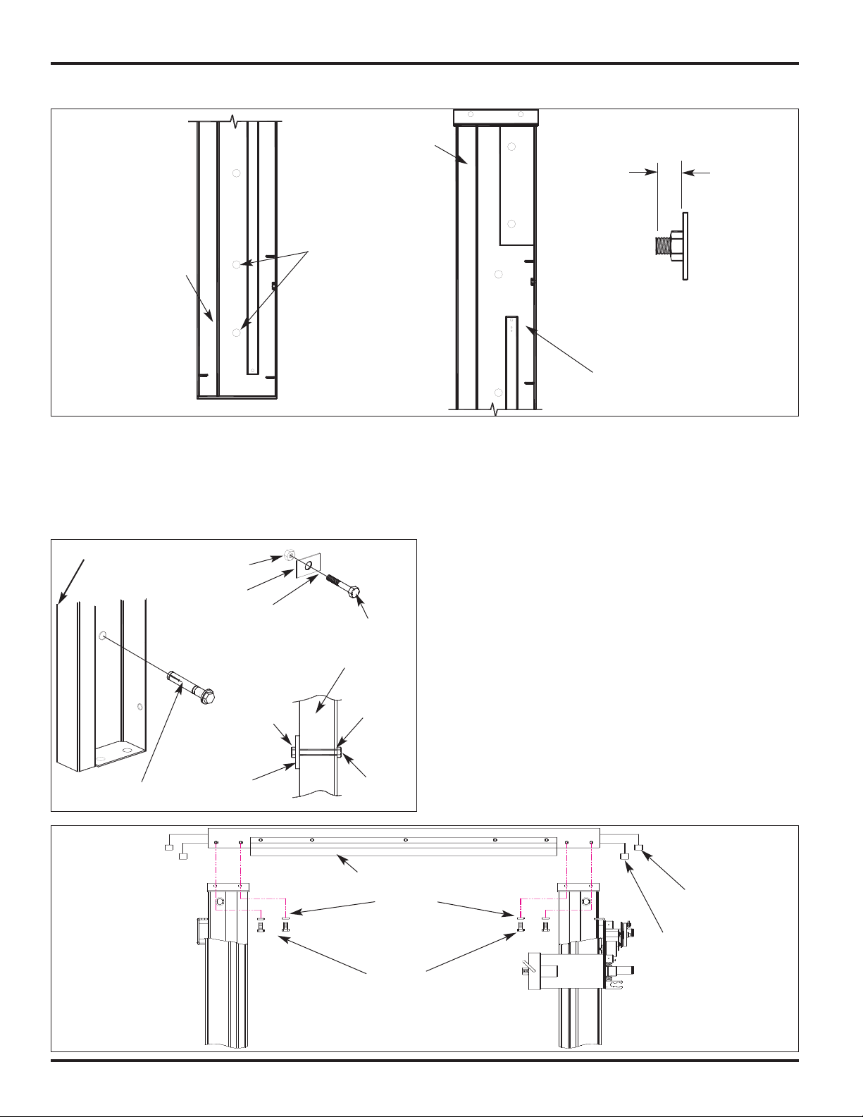
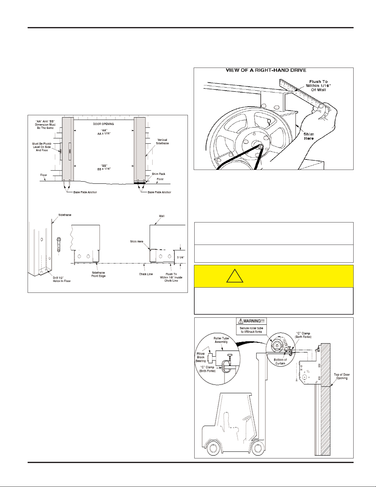
SIDEFRAME INSTALLATION . . . . . . . . . . . . . . . . . . . . . . . . .4
ROLLER TUBE INSTALLATION . . . . . . . . . . . . . . . . . . . . . . .6
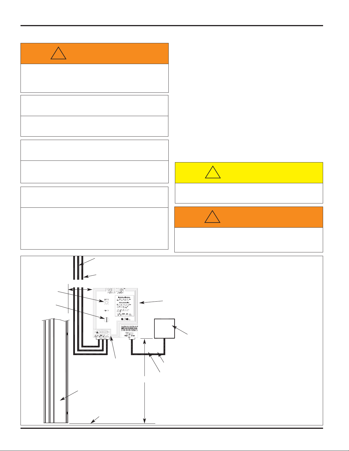
CONTROL BOX INSTALLATION . . . . . . . . . . . . . . . . . . . . . . .8
LIMIT SWITCH ADJUSTMENT . . . . . . . . . . . . . . . . . . . . . . . .10
TROLLEY AND S/F COVER INSTALLATION . . . . . . . . . . . . .11
PHOTOEYE INSTALLATION . . . . . . . . . . . . . . . . . . . . . . . . . .11
JUNCTION BOX INSTALLATION . . . . . . . . . . . . . . . . . . . . . .13
TURN-TITE®SEAL ADJUSTMENT . . . . . . . . . . . . . . . . . . . .14
INPUTS & OUTPUTS ON PLC . . . . . . . . . . . . . . . . . . . . . . . .15
FINAL INSTALLATION CHECKLIST . . . . . . . . . . . . . . . . . . . .16
MAINTENANCE CHECKLIST . . . . . . . . . . . . . . . . . . . . . . . . .15
BRAKE ADJUSTMENT . . . . . . . . . . . . . . . . . . . . . . . . . . . . . .19
TROUBLESHOOTING, REPAIR, AND ADJUSTMENTS . . . . .20
ELECTRICAL DRAWINGS . . . . . . . . . . . . . . . . . . . . . . . . . . . .23
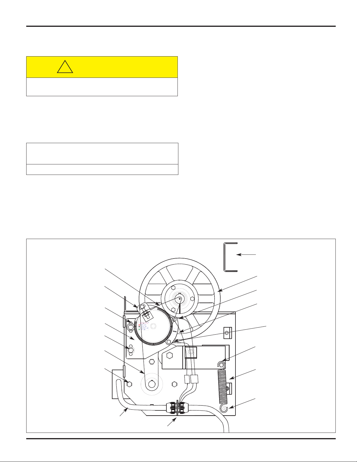
COUNTER BALANCE SYSTEM . . . . . . . . . . . . . . . . . . . . . . .26
OPTIONAL INVERTER & THRU-WALL RELEASE . . . . . . . . .27
ARCHITECTURAL DRAWING . . . . . . . . . . . . . . . . . . . . . . . . .28
NOTICE TO USER
Your local RITE-HITE DOORS, INC. representative provides a
Planned Maintenance Program (P.M.P.) which can be fitted to your
specific operation. If any procedures for the installation, operation
or maintenance of the Protecdor system have been left out of this
manual or are not complete, contact your local representative or
RITE-HITE DOORS, INC. Technical Support at 1-563-589-2722.
RITE-HITE DOORS, INC. are covered by one or more of the following
U.S. patents: 5,025,846, 5,143,137, 5,203,175, 5,329,781, 5,353,859,
5,392,836, 5,450,890, 5,542,463, 5,579,820, 5,601,134, 5,638,883,
5,655,591, 5,730,197, 5,743,317, 5,794,678, 5,887,385, 5,915,448,
5,944,086, 5,957,187, 6,042,158, 6,089,305, 6,098,695, 6,145,571,
6,148,897, 6,192,960, 6,321,822, 6,325,195, 6,330,763, 6,352,097,
6,360,487 including patents applied for, pending, or issued.
PRODUCT INTRODUCTION
Thank you for purchasing the Protecdor CL from RITE-HITE DOORS,
INC. The Protecdor CL door is a smooth opening, low maintenance
door that is designed to provide superior environmental separation
while reducing passage time and temperature loss. The door is
designed for The information contained in this manual will allow you to
operate and maintain the door in a manner which will insure maximum
life and trouble free operation. This manual should be thoroughly read
and understood, before operating or servicing this door.
To be sure that you receive the correct parts, always include your
door serial or RHC # (RITE-HITE CORPORATION) when ordering
through Aftermarket or the Warranty department. The RHC and serial
# for your door is on a label located on the side of the control box.
The actual parts used on your door may be different than shown in
this manual due to special engineering or product improvement.
FEATURES
- Soft-Edge™ safety system.
- Heat sealed FDA compliant fabric for a smooth, clean surface.
- Stainless Steel components withstand corrosion.
- Harsh Environment washdown motor and brake.
- Internal sensing system stops door immediately without coil
cords or external electronics.
- Quick release hinged sideframe cover for cleaning and curtain
re-feed.
- Standard Thru-Beam photoeyes
- Sealed electrical components
RECOMMENDED SPARE PARTS LIST
Open Limit Switch 15650061
Closed Limit Switch 15650062
Proximity Magnet 72700009
Photoeye Internal 63900003
Photoeye External 63900001
Photoeye Reflector 66400001
Drive Belt 12550013
Wind Retention Clips 53700124
TOOLS AND MATERIALS REQUIRED
Tubes of RTV Silicone Caulk Forklift Lift and Scissors Lift
9/16” Open End Wrench 9/16” Socket
Phillips Screwdriver 8’ or 10’ Step Ladder
Hammer Drill Cordless Drill (3/8” or 1/2”)
Tape Measure 25’ Minimum Utility Knife
6’ Carpenters Level Plumb Bob
(2) 18” “C” Clamps Wire Strippers
Straps For Lifting Header (optional) 3/8” and 5/8” Masonry Bits
Hardware for mounting door and anchors for fastening
sideframe to concrete are not supplied.
WARRANTY
RITE-HITE DOORS, INC. warrants that it’s Protecdor Clean,
including electrical components, will be free from defects in
design, materials and workmanship for a period of one (1) year,
or 150,000 cycles, from the date of shipment, whichever shall
first occur. It does not cover damage incurred from abuse,
misuse or impact. Belting, fuses, bulbs and fogging or frosting of
vision window, are not considered to be covered by warranty. All
claims for breach of this warranty must be made within thirty
(30) days after the defect is or can, with reasonable care, be
discovered. To be entitled to the benefits of this warranty, the
products must have been properly installed, maintained,
operated within their rated capacities, and not otherwise
abused. Periodic lubrication and adjustment is the sole
responsibility of the owner. This is RITE-HITE DOORS, INC.
exclusive warranty. RITE-HITE DOORS, INC. expressly
disclaims all implied warranties of merchantability and fitness.
Non-standard RITE-HITE DOORS, INC. warranties, if any, must
be specified by RITE-HITE DOORS, INC. in writing.
In the event of any defects covered by this warranty, RITE-HITE
DOORS, INC. will remedy such defects by repairing or replacing
any defective equipment or parts, bearing all of the costs for
parts, labor, and transportation. This shall be the exclusive
remedy for all claims whether based on contract negligence or
strict liability. Neither RITE-HITE DOORS, INC. Any other
manufacturer whose products are the subject of this transaction,
nor any RITE-HITE DOORS, INC. representative shall in any
event be liable for any loss or use of any equipment or
incidental or consequential damages of any kind whether for
breach of warranty, negligence, or strict liability. The application
of a manufacturer's specifications to a particular job is the
responsibility of the purchaser.
8900 N. Arbon Drive
P.O. Box 245020
Milwaukee, Wisconsin 53224-9520
Sales: 414-355-2600
Toll Free: 800-456-0600
Aftermarket: 563-589-2781
Service: 563-589-2722
Service Fax: 563-589-2737
Representatives in All Major Cities
www.ritehite.com

Pub. No. 8000CLB FEBRUARY 2004 3
PROTECDOR® CL Model 8000CL
The following is basic information that you should review before
beginning the installation.
1. Make sure that you have any special work or building permits.
2. Make sure that you are working at the correct door location.
3. Inspect the installation site to make sure that there are no
overhead obstructions (sprinkler pipes, HVAC systems,
electrical supply lines, etc.) that might interfere with the
lifting of the header tube assembly during installation.
4. Detour material handling equipment (fork lift trucks, etc.)
during the installation of the door.
5. Move the entire crate of the door components as close to
the door opening as possible.
6. Make sure that the electrician is ready to bring the correct
electrical power supply to the door control box.
7. Make sure that the electrical power can be shut off without
interfering with other plant operations.
8. Verify that there is nothing buried in the floor (electrical
supply, communication lines, etc.) where the anchor bolts
will be installed.
9. When unpacking the door components remove the lighter
items first (electrical components), then the side frame
assemblies, and the roll tube assembly last.
NOTE:
Electrical prints included in the parts or control box,
supersede any prints included in this owners manual
on Pages 23-25. Always check for electrical prints.
It is important to verify the door opening to the door
size before starting with the installation.
1. Measure the overall width of the door opening near the
floor and near the top (Dimensions A and B), Figure 1.
These measurements should be within ± 1/4" of the sizes
listed on the Serial Number label for the door to be
installed.
2. Measure the height of the door opening at the left and
right-hand sides (Dimensions C and D), Figure 1. These
should be within ±1" of the dimensions listed on the Serial
Number label. If the measurements do not agree, STOP!
Contact your RITE-HITE DOORS, INC. representative.
3. Verify that the door jambs are plumb and perpendicular
and that the horizontal header is level.
4. Make sure that the floor is level using a 6’ carpenter’s
level or water level. If the floor is not level to within 1/4",
shimming of the sideframe assemblies will be required,
Figure 1.
SIDEFRAME INSTALLATION INSTRUCTIONS
1. Measure the door opening width approximately 48" above
the floor, Figure 1. If the door opening width is narrower
than the width of the door listed on the Serial Number
label, subtract the door opening width from the door width.
The difference between these two numbers should be
divided in half and added to each side of the door
opening. These points will be used as the inside edge
measurement AA and BB on Figure 4 between the
sideframe assemblies of the door.
Example:
Door width listed on the Serial Number label 12' 1"
Actual door opening width –12' 0"
Difference 1"
For example, the 1" difference needs to be added to
measurements AA and BB in, Figure 3. Half of this
dimension must be split between the centerline.
NOTE:
If the door is wider than the opening the breakaway
magnets may not function properly.
2. Snap a chalk line on the floor 3 1/4" from the wall and
extending at least 12" to either side of the door opening,
Figure 2. This will be the reference line used to keep the
sideframes square with each other.
INSTALLATION INSTRUCTIONS
LISTING OF MEASUREMENTS AND
MARKINGS REQUIRED
1. Door width at bottom
2. Door width at top
3. Door height left
4. Door height right
5. Mark left wall where water is level.
6. Mark right wall where water is level.
CD
Hydro-Level
A
B
48”
High Side Low Side
Level
FIGURE 1
Make sure to barricade the door opening on
both sides to prevent unauthorized use until the
door has been completely installed.
CAUTION !!!
!
FIGURE 2
12” 12”
“E” “E”
Wall
Chalk
line
Center line
3 1/4”

4Pub. No. 8000CLB FEBRUARY 2004
PROTECDOR® CL Model 8000CL
SIDEFRAME INSTALLATION INSTRUCTIONS
3. Using a water level or string level, determine if the door
opening is level, Figure 1. If the opening is not level,
mark the wall where the level point is indicated. The
measurement between the level mark the floor is the
amount of shimming that needs to be done under the
sideframe assembly that will be located on the “Low Side”
(greatest measurement) of the door opening.
4. Remove both sideframe covers and the motor shroud.
5. Position the high side sideframe on the wall using the
offset dimension from Step 1 and using a 6’ level, make
sure that the sideframe assembly is square and plumb in
two directions. Use shims as required to square up the
sideframe assembly to the chalk line.
NOTE:
If no shimming is required, mount the motor drive
side sideframe assembly first.
6. Using the predrilled holes in the sideframe assembly as a
guide, drill the anchor holes for the wall bolts, Figure 4.
If the anchor hole goes completely through the wall, use
thru-bolts and backing plates to secure the sideframe
assembly to the wall. Use all available anchor holes to
secure the sideframe assemblies. It is especially important
to fully secure the top hole of each sideframe assembly
with a thru-bolt. Install the fasteners finger tight.
7. Position the low side sideframe on the wall using the
offset dimension from Step 1. Insert the required number
of shims underneath the sideframe base plate to level the
sideframe, Figure 1. Using a 6’ level, make sure that the
sideframe assembly is square and plumb in two
directions. Repeat Step 6 for the low sideframe.
FIGURE 3
This clearance to show
mounting bolts above
track only
No bolts may
interfere with track
Internal Sensing
System track
1/2” Max
Upper right hand
sideframe
Lower right
hand sideframe
FIGURE 5
FIGURE 4
Header Seal Assembly
Washers
Internal Sensing
System Cable
Thru-Beam
Photoeye Cable
3/8” Bolts
IMPORTANT:
Thru-bolt or anchor head
MUST NOT stick out
more than 1/2”
Sideframe Nut
Thru-bolt
Washer
Wedge type
Sideframe
Backing plate
Backing plate
Nut
Thru-bolt
Washer

Pub. No. 8000CLB FEBRUARY 2004 5
PROTECDOR® CL Model 8000CL
8. Be sure that the wires and connectors coming out of each
end of the crossbeam and top of the sideframes are free
and clear before fastening the crossbeam, Figure 5.
NOTE: Solid plastic or metal shims must fully support the
sideframe base plate. Drill through the shims to
allow for the proper installation of the anchor bolts
9. Install the top seal crossbeam to the sideframe
assemblies and secure with two 3/8" x 1" bolts and flat
washers at each end, Figure 5.
10. Check the front edge of the sideframe assemblies for
squareness by referencing the chalkline, Figure 6.
NOTE: Front edge of sideframe assembly must be flush or
within 1/8" inside of chalk line, if not install solid
plastic or metal shims behind the sideframe
assembly to align the sideframe with the chalk line.
11. Using the predrilled holes in the sideframe assembly base
as a guide, drill the anchor holes for the floor bolts into
the concrete, Figure 6. If the installation requires the use
of shims, predrill the shims to allow for the anchor bolt.
Install the anchor bolts and fully tighten.
12. Fully tighten all remaining anchor bolts or thru-bolts on
both sideframes. Check to see that the back of the
sideframe is flush with the wall, Figure 7. Make sure to
check that both the top of the sideframe and the top seal
crossbeam above the motor are flush with the wall. If a
gap on either side of the drive side sideframe of more
than 1/16" is noticed, insert metal shims to fill the gap
before tightening the thru-bolts. Make sure to position the
shims as close to the thru-bolts as possible. This is
important at the top of the drive side sideframe assembly
to make sure that the drive motor and pulleys are aligned.
NOTE: If this procedure is not followed, the sideframe
assembly could be twisted slightly, causing the
drive belt and limit switch belt to not track properly.
ROLLER TUBE ASSEMBLY / DRIVE BELT
NOTE: When overhead fork truck mast clearance is a
problem, additional support blocks will need to be
added under the roller tube assembly. Securely attach
wooden supports to the roller tube assembly and lift
into position as stated in normal installation procedures.
SIDEFRAME INSTALLATION INSTRUCTIONS
FIGURE 6
FIGURE 7
FIGURE 8
DO NOT remove the shipping bands from the roller
tube assembly before completing installation.
IMPORTANT!!!
Secure the roller tube assembly to the lift truck
forks before attempting to position the roller
tube assembly, Figure 8.
CAUTION !!!
!

6Pub. No. 8000CLB FEBRUARY 2004
PROTECDOR® CL Model 8000CL
1. Use a lift truck, lift and position the roller tube assembly
above the sideframes, Figure 8.
2. Carefully lower the roller tube assembly into position on
top of the sideframes by aligning the bolt holes in the
pillow blocks and the mounting brackets, Figure 9.
3. Align and fully tighten the drive side roller tube mounting bolts.
NOTE: The non-drive side uses 7/16" x 1 1/4" bolts, flat
washers, and tapered washers; the drive side
uses 7/16" x 1" bolts and lock washers.
4. Align the roller tube mounting bolts and tapered washers
on the non-drive side and fully tighten. If necessary,
loosen the two set screws on the pillow block bearing to
align mounting holes. Tighten the two bearing block set
screws on the non-drive side to 66 to 80 in/lbs. of torque.
5. Using a 12" long straight edge, check to see that the large
pulley is square with the motor mounting plate. Place the
straight edge perpendicularly along the outside face of the
motor mounting plate and measure at the front and back
of the pulley, Figure 11. If these measurements are not
within 1/16", shim behind the drive side sideframe
assembly. Refer to Step 11 on Page 5.
6. Install the drive belt onto the drive pulley on the motor and
then position the belt on the large pulley on the roller tube
assembly, Figures 10 & 11. Make sure that the belt ribs
are fully seated in the grooves of both pulleys.
7. Engage the tensioning system by pulling the loose end of
the tension spring downward and hooking the spring end
over the anchoring peg, Figures 10 & 13. Make sure to
position both of the spring ends (top and bottom) in the
grooves of the nylon bushing.
8. Using a straight edge, measure the distance between the
drive belt and the motor plate at the large pulley and at
the motor pulley. The measurement taken at the motor
pulley must be within 1/32" of the measurement taken at
the large pulley. If an adjustment is required, loosen the
motor pulley set screws and align the motor pulley as
required. Tighten the set screws and recheck the
measurement, Figure 11.
ROLLER TUBE ASSEMBLY / DRIVE BELT
FIGURE 9
Pillow block
bearing w/ set
screws
7/16” x 1-1/4”
Bolt
Flat Washer
Roller tube assembly Pulley
Tapered Washer
7/16” x 1” Bolt
Lock Washer
FIGURE 10
VIEW OF A RIGHT-HAND DRIVE
3/4” 1”
FIGURE 11
Bottom Edge
Brake
Release
Handle
Drive Belt
Large Driven Pulley
Motor Pulley
with set screws
Straight Edge
“X” =/- 1/32”
“X”

Pub. No. 8000CLB FEBRUARY 2004 7
PROTECDOR® CL Model 8000CL
9. Remove the curtain shipping band. The curtain will not
unroll because the brake is holding the curtain in position.
10. Using the manual brake release handle, disengage the
brake and slowly lower the curtain until the bottom is even
with the top of the door opening, Figure 11. Release the
manual brake lever to hold the door in this position.
11. Rotate the large limit switch pulley to align the magnet
assembly with the red OPEN limit switch, Figure 12.
12. Install the limit switch belt over the small pulley on the
roller tube and the large pulley on the limit switch
assembly. Loosen the two 3/8" limit switch mounting bolts.
Make sure that the timing belt is seated in the grooves on
both of the pulleys.
13. Pull down slightly on the limit switch mounting plate to
apply tension to the timing belt and tighten the two 3/8"
bolts. In most cases, just the weight of the limit switch
assembly will provide enough tensioning.
14. Slide the 1" conduit fitting into the same bracket that the
3/4" motor conduit is secured to and tighten the lock nut,
Figure 10.
15. Connect and secure all mating wire connectors from the
motor, photoeyes, limit switches, and sensing system.
NOTE: The two photoeye connectors are red in color.
These must not be plugged into any other color
connector.
16. The door ground wire is pre-attached at the factory to the
door frame assembly by using the hex head screw and
star washer attached to the conduit mounting bracket,
Figure 12.
17. Secure all wires clear of moving parts with a wire tie.
18. Pull the manual brake release handle to slowly lower the
door until the curtain is 4" from the floor.
19. Locate the close limit switch adjustment plate. Loosen the
1/4” thumb screw and rotate the limit switch plate until the
black limit switch aligns with the magnet, Figure 12.
Lightly tighten the lock bolt.
NOTE:
The white tipped limit switch deactivates the
photoeye prior to the door fully closing.
ROLLER TUBE INSTALLATION
FIGURE 12
VIEW OF A RIGHT-HAND DRIVE
Limit Switch Drive Belt
Open Limit Switch (Red)
Adjustment Slots
Limit Switch Mounting Bolts
Drive Belt
Motor Bolts
Motor Cable
Ground Screw
Anchor Peg
Photoeye Deactivate
Switch (White)
Driven Pulley
Header Channel
Drive Belt Tension Spring
Closed Limit Switch
Adjustment Plate
Closed Limit Switch (Black)
Motor Drive Belt Tensioner
Limit Switch Mounting Plate
Keep hands and loose clothing away from the
pulleys and belts while manually releasing the brake.
CAUTION !!!
!
Do not over tension the limit switch timing belt.
IMPORTANT!!!

8Pub. No. 8000CLB FEBRUARY 2004
PROTECDOR® CL Model 8000CL
1. It is the responsibility of the buyer to provide electrical
service up to the control box with proper branch service
protection and an approved means of disconnect.
2. All control boxes should be mounted on the warm side
regardless of door mount side.
3. The incoming power terminals in the control box will not
accommodate wires larger than 12AWG. 20 or 30 Amp
service may be required for cable runs longer than 300’.
4. The control box is provided with class CC protective
fusing for the incoming power.
5. Mount the control box on a wall adjacent to the door at
approximately 54" above the floor level, Figure 13.
6. Run the control cable from the drive sideframe assembly
through the conduit fitting in the bottom of the control box,
Figure 13.
CONTROL BOX INSTALLATION
FIGURE 13
6” Min
Conduit
Fitting
Sideframe
Floor
54”
Control cable (1 15/16” flex conduit), comes prewired ready to attach to conduit
connector in the bottom of the control box. Individual wires need only be routed and
secured to the proper terminals. (Length provided is specified on original door order).
Control box (shipped with door), recommended mounting location is
approx. 54” from floor to bottom of box and minimum of 6” from door
side frame (consult salesperson for planned mounting location.)
Control box to activation (pull cords, motion detectors, etc.) conduit run (s), by others.
Fused disconnect (supplied by others), located next to where
the door’s control box is or will be located. See Pages 23-25 for
service amperage requirements given your specific line voltage.
Incoming voltage (see Pages 23-25 for acceptable voltages)
Control box to disconnect conduit run (by others).
When drilling holes in the box, do not allow the
drill to go too deeply into the box. Damage to
the control systems may occur.
CAUTION !!!
!
DO NOT turn control box upside down to drill any
access holes. Debris may fall into electrical components
causing failure or severe equipment damage.
WARNING!!!
!
When working with electrical or electronic
controls, make sure that the power source has
been locked out and tagged according to OSHA
regulations and approved local electrical codes.
WARNING!!!
!
The control box and all wiring should be
installed by a qualified electrician in accordance
with all national and local electrical codes.
IMPORTANT!!!
If rigid conduit is installed, bonding must be
maintained between conduit connections by
using ground bushings and a jumper wire.
IMPORTANT!!!
In freezer and cooler applications where a
conduit passes from a warm to cold temperature
zone, the conduit must be plugged with epoxy.
This will help prevent condensation from
forming in the conduit. For more information,
see Section 300-7a of the National Electric Code.
IMPORTANT!!!
Disconnect
Switch
Open/Reset
Button

NOTE:
Make sure to route the cable so that it does not
interfere with the installation of the motor shroud.
If the flexible conduit is too long for the
installation, cut the protective outer casing and
leave 16" to 20" of wires. Do not connect the
conduit to the fitting on the control box until
correct conduit and wire length is achieved.
Local electrical codes may require the use of rigid
conduit, rather than flexible conduit. If required,
remove the control cables from the furnished
flexible conduit, install the rigid conduit in its place
and rewire. Make sure to remove and replace the
conduit connector in the bottom of the control box.
7. Drill a hole for the power supply cable (by others) in the
bottom of the control box using the proper connection to
maintain the NEMA rating on the enclosure. All holes
drilled through the control box must be through the
bottom of the box.
8. Connect wiring as indicated by the device field wiring
located on Pages 23-25. Incoming 3-phase power must
connect into terminals L1, L2, and L3. Ground must attach
to the green/yellow terminal.
NOTE: Route all field installed wires so that separation is
maintained between line voltage wires and low
voltage class II wiring. Electrical prints included in
the parts or control box, supersede any prints
included in this owners manual on Pages 23-25.
Always check parts or control box for prints.
Pub. No. 8000CLB FEBRUARY 2004 9
PROTECDOR® CL Model 8000CL
CONTROL BOX INSTALLATION
FIGURE 14
GND L3 L2 L1 F2 F1 F4 F3 S4 S2 S3 S1 B2 B1 W V U GND
Top Pot Switch
is Reclose
Timer, Lower is
Preannounce
Illuminated
Input LED’s
Illuminated
Output LED’s
Illuminated
Run/Power
LED’s
Hand Held
Programmer
Receptacle

ADJUSTMENT OF LIMIT SWITCHES
1. Turn on the main power supply. Confirm that the correct
line voltage is at terminals L1, L2 and L3, Figure 14.
2. Make sure that fuses F1, F2, F3, and F4 are installed,
Figure 14.
3. Turn the power to the door on using the disconnect switch
located on the front of the control box. Verify that the PLC
is in the run mode.
4. Check PLC input 1, door close limit switch. This should be
turned on. If this is not on, check the close limit switch to
make sure that it is in alignment with the magnet on the
limit switch pulley.
5. Momentarily press the green OPEN button and observe
the door. If the door jogs downward, lockout and tag the
main electrical power and reverse the motor leads at
terminals V and W, Figure 14. Reconnect the power and
verify the correct door movement.
6. If the door jogs upwards, continue jogging until the door
reaches the OPEN limit switch.
7. Continue to jog the door by momentarily pressing the
OPEN button, the door will now move downward toward
the closed position. Continue until the door reaches the
CLOSE limit switch, approximately 4" off the floor.
NOTE:
In the “jog” mode, when the door reaches the
CLOSED limit switch, it will reverse direction.
If the door reaches the 4" measurement and does not
reach the Closed limit switch, turn off power to the
door and adjust the Closed limit switch, Figure 13.
8. Continue to jog the door until it is fully open.
PROTECDOR® CL Model 8000CL
10 Pub. No. 8000CLB FEBRUARY 2004
LIMIT SWITCH ADJUSTMENT
FIGURE 19
Connect
wires here
Be sure not to
pinch wires here
Junction Box
FIGURE 18
Snap Chain
Together Here
Attach Cables
With Screw Here
Internal Sensing System
Cable, On Back Side
Wheel
Sideframe
Right Side
Trolley
Door Opening
Magnet
Jumper Wire
3/4” Max

TROLLEYS
1. Locate the left and right hand trolley assemblies. Make
sure the trolley assembly has the wheels on the inside of
the sideframe and towards the back wall.
2. Verify chain and cable are connected to the trolley, Figure 18.
NOTE:
Covers must be installed with a 3/4" gap at the
curtain edge for proper trolley operation, Figure 17.
INTERNAL SENSING SYSTEM CABLES
1. Make sure to route the wire from the non-drive sideframe
thru the conduit of the header channel before putting on
the front cover, Figure 19.
2. Connect the wires from the drive sideframe and header to
the control box cable.
3. Be sure not to pinch the wires as the header channel is
installed, also be sure to have wires down in the
sideframe so the trolley does not catch on them.
PHOTOEYE INSTALLATION
1. Locate the Thru-Beam photoeye assembly in the drive
sideframe assembly, Figure 20. Located on the back end of
the photoeye assembly are three LEDs and one switch.
2. The yellow “Power ON” LED should be on when the door
power is turned on.
3. The “Light/ Dark” operate switch has been preset in the
“Light” operate position.
4. The red and green LED’s will be on when the photoeye
receiver and the source are lined up correctly. If the red
and green LED’s are OFF, either the beam is blocked or
the photoeye is out of alignment. Adjustment using the
screws on the sideframe assembly beneath the photoeye,
Figure 20. The two top screws allow for horizontal
adjustment and the single bottom screw adjusts vertical
alignment. Rotate the screw until the LED’s turn ON. If
after three turns the red and green LED’s do not turn on,
reverse direction.
After the red and green LED’s turn ON, continue to turn
the adjustment screw in the same direction, counting the
turns. Note when the LED’s turn OFF.
Divide the number of turns in half and reverse the turning
direction that number of turns to center the light beam.
Follow the same steps for the vertical adjustment until the
light beam is centered on the reflector.
Note: This photoeye is for reversing only, not remote
activation. Photoeye should be mounted at an
elevation of 24" from the floor (pre-drilled holes on
both sideframes). Disconnect power before
installing external mounted photoeyes.
EXTERNAL PHOTOEYE INSTALLATION
1. Locate the thru-beam photoeye components
(source, receiver, and mounting brackets).
2. Install the source photoeye on the non-drive side
sideframe. Install the photoeye receiver on the drive side,
Figures 22 & 23.
3. Insert the photoeye cable through the side of the
sideframe at the bottom and connect the cables together
at the connectors in the sideframe.
4. With the power on, adjust the thru-beam photoeye by
loosening the two mounting bracket screws and rotating
the bracket and photoeye assembly until the red LED
turns on.
5. Cable must be out of the inserts path.
Pub. No. 8000CLB FEBRUARY 2004 11
PROTECDOR® CL Model 8000CL
PHOTOEYE ADJUSTMENTS
The PROTECDOR CLEAN will not operate until
both the internal and external photoeye s have
been installed and aligned.
IMPORTANT!!!
FIGURE 22
FIGURE 20
Thru-Beam Photoeye
Assembly
Horizontal Adjustment
Vertical Adjustment
Drive Sideframe
Source

12 Pub. No. 8000CLB FEBRUARY 2004
PROTECDOR® CL Model 8000CL
STAND CLEAR INSTRUCTION LABEL
1. Clean surface where label is to be placed.
2. Peel off backing on label.
3. Apply label in proper position, Figure 24.
BREAKAWAY DETECTION SYSTEM
1. Jog the door down until it is approximately 4’ off the floor.
2. Attach the plastic magnet cup assemblies at each end of
the tension assembly to the magnets, Figure 18.
3. Remove excess slack by tightening the buckle.
4. Reattach the bottom loop seal.
MISC INSTALLATION
FIGURE 23
Photoeye
Source
#10-24X1/2” Bolt w/Lock
& Flat Washer
Nut
Bracket
24 5/8”
FIGURE 24
View of back Side Of Door
Label Both
Sides
12”
5’-0”
In the “jog” mode (OPEN button light flashing), the
door will raise as long as the OPEN button is
pressed. In the downward direction, the door will
only advance in short steps while the button is
pressed. Do not press the contactor to jog the door.
IMPORTANT!!!
Thru-Beam Emitter
Photoeye

PROTECDOR® POWER DOOR Model 8000
Pub. No. 8000CLB FEBRUARY 2004 13
JUNCTION BOX INSTALLATION
7810E001 Rev B 5/22/2003
Junction Box Layout

TURN-TITE SEAL ADJUSTMENT
The PROTECDOR CLEAN is equipped with an adjustable
TURN-TITE seal that runs across the entire door opening. Cycle
the door approximately 10 times to seat the door fabric.
Continue to cycle the door while standing on the back side of
the door opening. Look upwards and observe the gap between
the door opening and the roller tube assembly. No light should
be visible in the gap when the door is fully closed. If light is
visible, inspect the TURN-TITE seal from above. Adjust the seal
so that the sealing edge is aligned about halfway down the
angled face of the header seal and the TURN-TITE seal flexes
into the gap, Figure 30. Make sure to secure the hook and loop
fastener along the entire length of the roller tube.
Vertical Side Seals are seals located in the top corners of the
door when it is closed, Figure 30. These seals fill the gap
between the curtain fabric and the sideframe assembly just
below the roll tube. If a gap is visible along either side edge,
remove and re-install the seal.
CURTAIN RETENTION CLIPS
1. Retention clips have been installed on the Protecdor
curtain assembly for pressure resistance, Figure 31.
2. They are located above and below the vision panel at the
edge of the curtain.
3. There are four per door on doors under 11’ and six on any
doors over 11’ tall.
PROTECDOR® CL Model 8000CL
14 Pub. No. 8000CLB FEBRUARY 2004
TURN-TITE SEAL ADJUSTMENT
FIGURE 30
Correct TURN-TITE
and Vertical Side Seal
Move TURN-TITE Seal
Towards Top Of Roller Tube Move TURN-TITE Seal
Towards Header Wall Seal
Header Wall
Seal
Vertical Side
Seal
Roller Tube
TURN-TITE Seal
When working with electrical or electronic
controls, make sure that the power source has
been locked out and tagged according to OSHA
regulations and approved local electrical codes.
WARNING!!!
!
FIGURE 31
Cutout View of Retention
Clip in sideframe
Top View of Curtain with
Retention Clip in sideframe
Retention Clips
Internal Sensing
System cable
Must be set at 3/4” gap
Tension
Cable

Pub. No. 8000CLB FEBRUARY 2004 15
PROTECDOR® CL Model 8000CL
PLC INPUT/OUTPUT & MAINTENANCE CHART
RITE-HITE DOORS, INC. PLANNED MAINTENANCE
Model 8000 PROTECDOR®
CUSTOMER:
RHC# SERIAL# DATE:
Periodic Cycle Check:
Planned Maintenance
Brake
Controls
Curtain
Drive Belt
Internal Sensing System
Limit Switches
Limit Switch Belt
Magnets
Photoeye
Pillow Block Bearings
Seals
Sideframes/Shroud/Header
Recommended P.M. Intervals
(Time Shown In Months)
1
Inspect and Perform the Following (See Manual)
With door in the open position, manually release the
brake by pulling the handle, but DO NOT let it free
fall to the bottom. Check that door stops on limits, if
not check air gap of brake, must be .008”.
Clean, check all connections with disconnect off.
Inspect for wear or damage, clean with isopropyl
alcohol or similar product.. Check retention clips.
Inspect for wear or squeaking, realign as required.
Replace if worn or frayed, must remove l/s belt.
Remove sideframe covers and perform visual
inspection of chain and cable. Check operation by
separating magnets from cups, door MUST stop and
green lite flash.
Check open and close positions.
Inspect for wear, realign as required, DO NOT
overtighten. When replacing, limits must be reset.
Inspect magnets and cups. Remove dirt and metal
shavings from face of magnet and plate. Apply small
amount of electrical grease if rust is present.
Check alignment, align as required. Clean reflector,
emitter and receiver.
Grease as required.
Adjust Turn-Tite as required in closed position.
Inspect wear on wall and curtain wedge seals,
replace as required.
Perform visual inspection for damage.
Tighten all hardware.
Check sideframe to cover gap at 3/4”
4
•
•
•
•
•
•
8
•
12
•
•
•
•
•
•
•
•
•
18
•
•
•
•
24
•
•
•
•
•
•
•
•
•
•
30 36
•
•
•
•
•
•
•
•
•
•
•

STANDARD OPERATING CONDITIONS
Operate the door under normal conditions. Observe the door
opening to make sure that it opens fully and does not interfere
with the header. Observe the closing action to make sure that
the door operates smoothly, and fully closes without excessive
curtain ripple at the bottom. The bottom edge needs to rest
completely on the floor for a good seal, adjust limits as required.
VERIFY DOOR OPERATION
1. It is recommended that the operation of all controls on the
CLEAN door be verified monthly.
2. A fault will occur when this condition exists:
To return the CLEAN door to normal operation:
Both magnet cups must be properly connected.
Press the OPEN button to reset.
3. If the door fails to function, contact your local RITE-HITE
DOORS, INC. representative.
TEST ALL SAFETY FEATURES
1. While the door is closing, block one of the reversing
photoeyes. The door should stop immediately and reverse
to the fully open position. Repeat this test for the second
reversing photoeye.
2. Internal Breakaway Sensing System testing requires that
the insert be broken away from the trolley. Do this while
the door is OPENING. The door should stop and the
open/reset button on the control panel will flash indicating
a fault. Press the reset button and/or reattach the insert to
the trolley magnet.
DISCONNECT SWITCH
The red Disconnect Switch stops door operation. The control is
rotated to the On position for normal door operation. To stop
door operation rotate the control to the OFF position, Figure 13.
Whenever the door is stopped by using the Disconnect Switch,
you must do the following to resume operation.
1. Rotate the red disconnect switch to the ON position.
2. Press the open/reset button to reset and open the door.
GREEN OPEN BUTTON
The green OPEN button opens the door and resets the door
after a fault condition. To open, press and release the button.
The PLC will automatically close the door after the preset time
has expired, Figure 13.
REMOTE ACTIVATION DEVICES
Operate the door system with any remote activation devices that
are in use. Make sure that the door fully opens and then closes
after the time set on the re-close timer has expired.
PROGRAMMABLE LOGIC CONTROLLER
1. The door operations are controlled by a Programmable
Logic Controller (PLC), Figure 14. The PLC is used to
control all functions of the door. The PLC is set-up and
programmed during testing at the factory. Unless you are
trained in PLC adjustments and are a RITE-HITE
DOORS, INC. authorized service technician, you should
not attempt to change the factory set program.
2. A quick way of determining that the door is ready to
operate, is to open the control box and look at the PLC.
On the face of the PLC are two rows of small red lights
called Light Emitting Diodes (LED’s). The top row of LEDs
are numbered and called INPUTS, these are also referred
to as X-Inputs. They indicate the condition of the inputs for
door, such as #0 open limit switch, #1 close limit switch.
The bottom row of LEDs are also numbered and called
OUTPUTS, these are also referred to as the Y-OUTPUTS.
3. Refer to the state table of “Inputs and Outputs on PLC,”
located on Page 15 of this manual, to verify the lights that
are on or off are correct.
4. Figure 14 gives you an example of the standard PLC used
in the control box and also an optional PLC.
Run/Stop Switch
The Run/Stop switch is located under the small cover on the
lower edge of the PLC, Figure 14. The Run/Stop Switch is
normally in the Run position. The only time the switch is moved
to the Stop position is when an authorized person reprograms
the PLC. When the switch is in the Stop position the door will
not function.
Re-close Timer
The timer is part of the PLC. The adjustment for the timer is
located under the small cover on the lower edge of the PLC,
Figure 14. The timer controls the amount of time that the door
remains open after activation by a remote device (pull cord,
induction loop, etc.). When the amount of time set expires, the
door automatically closes.
FINAL INSTALLATION CHECKLIST
1. With the power on and the breakaway detection system
installed, press the OPEN button. The door should open
and close automatically after a short delay. To adjust the
amount of door open time, locate and turn the adjustment
screw on the front of the PLC, Figure 14.
2. Operate the door several times and observe the opened
and closed positions. If it is necessary to adjust either
position, shut the power off and simply move the open or
closed limit switch, Figure 12. Tighten the limit switches
after adjustment is final.
3. While the door is operating, break away the magnet on
one side of the door to make sure that the breakaway
detection system is working. The door should stop and the
OPEN button light should flash. Reattach the magnet and
press the OPEN button to restart the door.
4. While the door is closing, block the internal and external
photoeyes. The door should reverse direction and move to
the open position, and then continue to operate.
5. Install motor shroud.
6. Are door opening dimensions correct ?
PROTECDOR® CL Model 8000CL
16 Pub. No. 8000CLB FEBRUARY 2004
OPERATING INSTRUCTIONS

7. Did you check for proper frame alignment when installing
floor anchor bolts and shim as required ?
8. Did you install a wall mounting bolt in the top hole of both
sideframes and tighten all mounting bolts ?
9. Did you tighten the pillow block bearing set screws on the
non-drive side to 66 to 80 in.-lb. ?
10. Did you check drive belt alignment to within 1/32" ?
11. Are loose wires secured away from moving parts?
12. Did you check for proper line voltage ?
13. All wires connected for the internal sensing system and/or
thru-beam photoeyes ?
14. Sideframe covers adjusted to 3/4” gap clearance ?
TIPS FOR BREAKAWAY REASSEMBLY
The Protecdor Clean is equipped with a breakaway “Internal
Sensing System”. The system is a quick and easy re-assembly
of the curtain after a breakaway occurs. When a breakaway
condition is acknowledged the door will stop, the OPEN button
will flash, and operation will convert to JOG mode.
The “Internal Sensing System” is a thru-wire closed loop circuit
which monitors continuity through the breakaway system. When
continuity is disrupted by the separation of one or both of the
breakaway magnets, a breakaway condition is acknowledged.
To return to normal operation, if the magnets are separated, re-
attach and press the open button.
If the door is in jog mode (OPEN button flashing):
Problem: The door is broken away and one or more of the
retention clips are outside the front cover.
Solution: Open the sideframe front covers. Jog the door to the
top and back down to a convenient height for re-
assembly of the magnets. Close front covers.
Problem: The curtain bunches up enough to stall the motor.
Solution: Turn power off. Release the manual brake handle in
short intervals until the curtain reaches floor or the
wrinkles are cleared. Turn the power back on and jog
the door to the top. Open the front covers and jog the
door down to reassemble the magnets.
SHROUD INSTALLATION
1. Run door to the full open position and disconnect the
power and lock/out tag/out and barricade traffic.
2. Position center shroud and fasten with 1/4” hardware.
3. Position drive shroud and fasten with 1/4” hardware.
4. Position non-drive shroud and fasten with 1/4” hardware,
and self tap screw.
5. Return power to door and verify operation, remove
barricades and return door back to service.
MISC PHOTOS
1. See the two figures above for gaining access to the
sideframe.
2. The sideframe is opened by stepping on the Quick
Release system lever located on the outside edge of
either sideframe and swinging the door open.
3. In the event of the curtain coming out of the sideframe,
the front cover will need to be opened to place the curtain
back in the sideframe.
PROTECDOR® POWER DOOR Model 8000
Pub. No. 8000CLB FEBRUARY 2004 17
OPERATING INSTRUCTIONS
FIGURE 36
Center Shroud
Non-Drive
Sideframe
Drive Shroud
Drive Sideframe
Non-Drive
Shroud
1/4” Bolt w/Washer
DRIVE SYSTEM
Junction Box

18 Pub. No. 8000CLB FEBRUARY 2004
PROTECDOR® CL Model 8000CL
MISC DOOR PHOTOS
FRONT COVER EXTENSION
OUTSIDE FRONT COVER LATCHING MECHANISM
INSIDE FRONT COVER LATCHING MECHANISM
Latching Mechanism
Sideframe Front Cover
Step Down Latching
Mechanism
BREAKAWAY SYSTEM
BELT TENSIONER
BOTTOM LOOP COVER
BREAKAWAY CHAIN & TRACK SYSTEM
FRONT COVER
LATCHING MECHANISM
Bottom Loop Seal
Breakaway System
Trolley
Magnet & Cup
Photoeye & Internal
Sensing System Cables
Internal Sensing
System Cable

Pub. No. 8000CLB FEBRUARY 2004 19
PROTECDOR® CL Model 8000CL
AIRGAP:
1. In most applications, the brake needs practically no
maintenance. However after a long period of operation, or
if the brake has high duty cycles, adjustment of the air
gap may be necessary.
2. Check the air gap with a feeler gauge in three positions.
Note: the air gap is shown in Figure 33. The normal
setting is .008”. When the maximum dimension of .015” is
exceeded, adjust the value back to the normal dimension
of .008” using the instruction in Step 3.
3. If air gap adjustment is necessary, loosen the bolts (9A),
rotate the adjustment tubes (8) approximately 1/4 turn,
retighten bolts (9A), and measure the air gap. If air gap is
not within tolerance, repeat procedure.
TORQUE:
1. The brake is supplied from the factory with the nominal
torque setting. This torque can be reduced by unscrewing
the torque adjustment ring (3) with a spanner wrench. Do
not unscrew the ring further than it’s limit of .330” (approx.
5/16”) as shown as dimension “0”1 in Figure 34.
2. The torque adjustment ring has detent action with torque
variation of .443 ft-lb, per step.
BRAKE REPLACEMENT
1. Run the door to the full open position and disconnect power
to the door. Make sure that the power source has been
locked and tagged out according to OSHA regulations and
approved local electrical codes. Barricade the work area on
both sides of the door to prevent unauthorized access while
servicing.
2. Loosen the brake release handle by unscrewing it, then
loosen, but don’t remove the the three holding the cover
to the brake, this cover can be reused, Figure 34.
3. Disconnect the two white brake wires from the two blue
motor wires.
4. Using a 9/16” wrench, loosen and remove the two bolts
holding the brake to the motor, note orientation before
removing. Pull the brake straight off the motor, use
extreme care when pulling the blue motor wires thru the
holes in the brake to avoid stripping the insulation.
5. If the spline hub needs replacing, loosen the set screw.
When installing the new spline, be sure to use a thread
locking compound on the set screw and torque to 55 lb/in.
6. Install the new brake by first inserting wires thru the hole
in the brake and carefully pulling them thru as the brake is
slid on, use extreme care to avoid pinching the wires
between the motor and brake.
7. Thread the (2) 3/8” bolts thru the brake and into the motor,
torque to 22 lb/ft and reconnect the two white brake wires
to the two blue motor wires. Polarity is not important.
8. Replace the brake cover and tighten the three screws.
9. Screw the brake release handle on the brake and tighten.
10. Make sure there is play in the handle and it does not
catch or drag on the brake cover.
11. Reconnect power and check for proper operation.
BRAKE ADJUSTMENT
FIGURE 34
Remove 3/8” bolts
Brake Spline/Key
Motor/Brake Wires
Brake
Release
Handle
Brake Wires
FIGURE 33

20 Pub. No. 8000CLB FEBRUARY 2004
PROTECDOR® CL Model 8000CL
TROUBLESHOOTING, REPAIR AND ADJUSTMENTS
DEFINITION FUNCTION
PLC input X0 Open limit switch PLC input X0 LED for the open limit switch will illuminate as the limit switch magnet is lined up
with the red open limit switch. The LED will then go off as the magnet passes the open limit
switch. The limit switch is a normally open switch and will close when the magnet and switch
are aligned, thereby illuminating the X0 LED. MUST HAVE 1/8” gap between the magnet and
the switch. Faulty limit switch, replace. Brake did not engage, check wiring and proper 110VAC
voltage.
PLC input X1 Closed limit switch PLC input X1 LED for the closed limit switch will illuminate as the limit switch magnet is lined up
with the black closed limit switch. The LED will then go off as the magnet passes the closed
limit switch. The limit switch is a normally open switch and will close when the magnet and
switch are aligned, thereby illuminating the X1 LED. MUST HAVE 1/8” gap between the magnet
and the switch. Faulty limit switch, replace. Brake did not engage, check wiring and proper
110VAC voltage.
PLC input X2 Breakaway System PLC input X2 LED for the breakaway system will illuminate if all reversing or breakaway
mechanisms are functioning properly. This LED MUST BE ON for the door to run, if it is not
illuminated the door will not run. Both trolley magnets, MUST BE hooked to the curtain magnet
cups. A continuously monitored wire must be in contact all the time and not shorted to ground
for the system to work. The following are reasons for X2 not being on.
a) Sideframe cover gap too wide, must be at 3/4” or trolley may short out to sideframe.
b) Internal Sensing System lacks continuity, must have continuity through wires from
terminal 5 and 55, but not to ground.
c) Sensing System cable is to loose or tight. If cable is to tight it may pull apart the magnet
from the cup.
d) F5 fuse is not closing after a breakaway-replace fuse.
e) Trolley magnets are separated from the magnet cups.
f) Incorrect wiring or plug in connections, refer to electrical drawing for wiring.
PLC input X3 Reset button PLC input X3 LED for the reset button and will illuminate when the button is pressed. If the input
is not illuminated or the door will not open when pressed, check wiring from terminal 14 to input
X3 on the PLC.
PLC input X4 Photoeye limit switch PLC input X4 LED for the reversing photoeye will illuminate as the limit switch magnet is lined
up with the white photoeye limit switch. The LED will then go off as the magnet passes the
photoeye limit switch. The limit switch is a normally open switch and will close when the magnet
and switch are aligned, thereby illuminating the X4 LED. This switch will deactivate the
reversing photoeye’s as the door closes, to prevent the door from reversing as it reaches the
photoeye. Follow the reasons below, for why the X4 input light will not come on.
a) MUST HAVE 1/8” gap between the magnet and the switch.
b) Faulty limit switch, replace.
c) Check photoeye wiring, and plug in connections.
d) Raise the closed limit switch to deactivate the photoeye sooner.
e)If the X4 input light does not illuminate and deactivate the reversing photoeye’s, the bottom
loop seal of the curtain will break the light beam of the photoeye and reverse the door. The
bottom loop seal, may need to be raised on the hook and loop fastener, so the photoeye’s will
be deactivated before the curtain reaches the photoeye’s.
PLC input X5 Toggle activation PLC input X5 LED for the toggle mode will illuminate when activation devices are wired to
terminal 13. The toggle mode allows the user to push or pull an activation device to open the
door, and then push or pull a second device to close the door, rather than operating the door in
an auto-reclose mode.
PLC input X6 Activation PLC input X6 LED for the activation and will illuminate when activation devices wired to
terminals 63, 64, or 65 are triggered. The auto-reclose mode allows the user to push or pull an
activation device to open the door, and walk away allowing the door to close after a preset time.
The X6 input MUST BE OFF for the door to close, if door is stuck open, remove all activation
device wires until the faulty device is found.
PLC input X7 Photoeye PLC input X7 LED for the photoeye will be off when either of the reversing photoeyes are
blocked or misaligned. Both reversing photoeyes MUST BE ALIGNED with all 3 lights on or
door will stay open. X7 input MUST BE illuminated for the door to close.
PLC input X10 P.R.O. system fault PLC input X10 LED is illuminated when the door is faulted.
PLC input X11 I-Zone enable PLC input X11 LED must be illuminated to enable the I-Zone.
PLC input X12 I-Zone sensor 1 PLC input X12 LED will be off when reversing and during holding open.
PLC input X13 I-Zone sensor 2 PLC input X13 LED will be off when reversing and during holding open.
PLC output Y0 User Out (interlock) PLC output Y0 LED is User defined for interlocking.
PLC output Y1 Reserved PLC output Y1 LED is Reserved for future use. On when closed.
PLC output Y2 Run Open PLC output Y2 LED for the run open will illuminate when the door is running open.
PLC output Y3 Run Close PLC output Y3 LED for the run close will illuminate when the door is running close.
PLC output Y4 User Out PLC output Y4 is User defined for pre-announce.
PLC output Y5 Fault PLC output Y5 LED for the Fault will illuminate when the door is not in fault.
This LED MUST BE ON for door to run.
PLC output Y6 I-Zone Alarm PLC output Y6 LED for the I-Zone will illuminate when the I-Zone alarm is on.
Table of contents
Other RITE-HITE Garage Door Opener manuals
Popular Garage Door Opener manuals by other brands

Deltadoors
Deltadoors LiftMaster SL400EVK installation manual

CAME
CAME 801XC-0120 quick start guide

Beninca
Beninca DU.350 Operating instructions and spare parts catalogue

Acoustic Research
Acoustic Research Garage Door Control Setup guide

Guardian
Guardian DCR2 Installation instructions and owner's manual

RTS
RTS DEXXO PRO RTS user manual