ritm Contact RC-1L ver. 2 User manual

Radio channel panic button
Contact RC-1L ver. 2
868 MHz
Data sheet
Device ID

2
1. Overview
The radio channel panic button Contact RC-1L ver. 2 (hereinafter referred to as panic
button) is designed for generating an alarm event on button pressing and transmitting it to
the radio channel receiver RDK-L 868 MHz.
Contact RC-1L has terminals for connecting a remote wired panic button.
The button features low power usage and up to 2 years of period of single battery
operation.
When the radio channel receiver RDK-L receives the alarm event, the state of the
appropriate receiver output changes.
2. Manufacturer
RITM Company
195248,
Energetikov avenue, building 30, block 8,
St Petersburg, Russia
Tel.: +7 911 795 02 02
3. Package content
The radio channel panic button Contact RC-1L ver. 2 1 pc.
868 MHz antenna 1 pc.
Battery CR123A
1 pc.
Fixing set 1
Data sheet 1 pc.
Package
1 pc.
3
4. Technical specifications
Parameter Value
Frequency range, MHz 868.7-869.2
Maximum receiver emitting power, mW 25
Alarm message delivery acknowledgement +
Maximum range of stable
communication, km, up to
Restrained urban conditions 1
Medium urban conditions 2
Open territory 8
Line-of-sight range 20
Period of singe battery operation, years12
Connected loops, pc. 1 pc. of dry contact type
Power supply voltage
(lithium-type battery CR123А), V
3
Maximum useful current, mA,
up to
Standby mode 0.025
Event transmitting 60
Dimensions (without antenna), mm 25×50×81
Weight (without battery), g, up to 60
Operating temperature range without battery, °С−40… +60
Operating temperature range with battery, °С−20… +50
1Estimated operation time is shown in case of several alarm events per day. Operating time
directly depends on event transmitting frequency as well as on temperature and signal reception
quality. In case of sub-zero temperatures the operating time is essentially decreased.
4
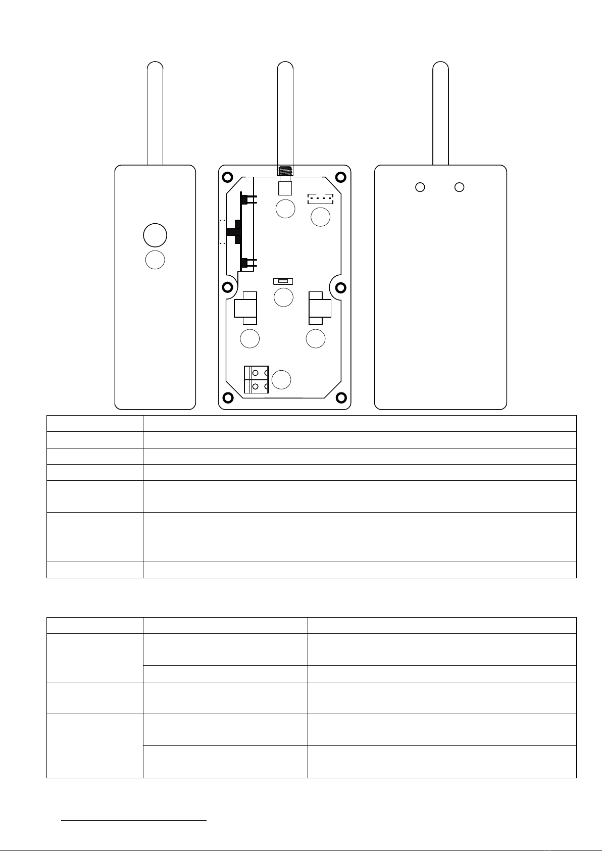
5. Unit designation
Unit
Designation
1
Panic button.
2
Button for changing operating modes.
3
Connector for 868 MHz antenna installation.
4
Special cable connector for communication with PC USB1 or USB2.
Used for updating version of the button software.
5, 6
Connectors for battery installing:
•Connector 6: for positive battery terminal connection;
•
Connector 5: for negative battery terminal connection.
7
Terminals for connecting an additional panic button.
6. Visual indication
Indicator
State
Value
Rx+Tx Blink one time
The button is added to the radio system of
the radio channel receiver.
Flash for 5 seconds
The radio system is not found
Rx Blinks one time
The transmitted alarm is received by the
radio channel receiver.
Tx
Blinks up to 5 times2at 1
time per 2 seconds
Failed to transmit the alarm.
Blinks two times
every 6 seconds
Battery is discharged.
2The panic button tries to transmit an alarm five successive times.
+
_
TxRx
1
2
34
56
7

5
7. Button designation
Button
Pressing duration time
Operation mode
1
At least 2 seconds
Alarm transmitting.
2 At least 2 seconds
Mode of adding the radio channel receiver
“RDK-L” to the radio system.
8. Setting-up procedures
1. Open the enclosure.
2. If necessary, connect an additional wired panic button to the terminals 7.
3. Install the battery CR123A to the connectors 5, 6.
4. Switch the radio channel receiver “RDK-L” intended to be used with the button to
the mode of adding devices (see the receiver operating manual).
5. Switch the panic button to the mode for adding to the receiver radio system (see
section 8).
6. Press the build-in panic button 1and ensure that the alarm is delivered to the
receiver (see the section 7).
For more details about successful adding the button to the receiver radio system and on
alarm transmission, use the radio channel receiver RDK-L configuration software.
Detailed information about interoperation with the radio channel receiver RDK-L see in
the Receiver operating manual available on the official website www.ritm.ru/en.
9. Maintenance
On a regular basis but at least twice a year check safety of contacts and if necessary
dress bonding pads.
Change battery as and when necessary.
10. Safety measures
All works related to installation, configuration and maintenance of the panic button
should be performed in accordance with the Electrical installation code and by qualified
personnel.
The radio channel panic button is a safe device, the maximum power supply voltage
level is 3 V.
11. Transportation and storage
The panic button should be transported in a package, in closed vehicles. Storage areas
should be free from current-conducting dust, acid and alkali fumes as well as active gases
able to corrode isolation.

6
12. Manufacturer warranty
The manufacturer warrants conformity of the panic button to the specification
requirements provided the transportation, storage, mounting and operation conditions are
observed by the consumer.
Warranty operating life — 12 months from the date of commissioning, but no more than
18 months from the date of manufacture.
Warranty shelf life — 6 moths from the date of manufacture.
The manufacturer reserves the right to make changes, not deteriorated of panic button
functionality without previous notice of consumers.
13. Reclamation details
In case of panic button failure or defect in the warranty period take a fault report stating
the date of button manufacture and commissioning, nature of a defect.
Send the faulty panic button with the fault report to the purchase address or to the
manufacturer.

7
Notes

8
Notes
Data sheet date 22.04.2019
Table of contents


