manuals.online logo
Brands
  1. Home
  2. •
  3. Brands
  4. •
  5. Ritron
  6. •
  7. Media Converter
  8. •
  9. Ritron GateGuard GGT-1 User manual

Ritron GateGuard GGT-1 User manual

GateGuard Model GGT-1/1F
DTMF Decoder
505 West Carmel Drive, Carmel, IN 46032 USA
P.O. Box 998, Carmel, IN 46082- 998 USA
PH: 3 7-846- 20  FAX: 3 7-846-4978
Web: www.ritron.com  Email: [email protected]
GateGuard
Model GGT-1/1F DTMF DECODER
PROGRAMMING & CONNECTION INSTRUCTIONS
Internal Relay Contact Specifications: Normally Open, 125 VAC @ 10amps
Warning! Do not exceed maximum rating.
I M P O R T A N T !
1. If you purchased the R X-454 Call Box (Basic or XT model) with the GGT-1 GateGuard DTMF Decoder,
you must use the RITRON Model EXPO-12 External Power 12VDC Input/Battery Back-Up Kit. The R X-
454 does not have a connection available that would allow both the Decoder Board and the R X radio
board to be turned off and draw no current when used only with batteries. The R X-150 and 450 do have
the necessary connection available, and can be used with batteries only or with the EXPO-12.
2. When using an XT Model Callbox with the RITRON Model EXPO-12, the installation of the liquid tight
strain relief in the EXPO-12 must be reversed due to space limitations in the XT case.
3. When using the GGT-1/1F with the 6-Series Callbox, the 6 D-cell battery holder must be removed and the
unit powered by an external 12 VDC power supply.
Step 1. - CALLBOX DISASSEMBLY - Basic and XT Models R X-150/156/450/456/454
1. For XT Model - Remove (4) metal screws with Torx T-25 Tamper-proof screw bit. Remove front metal plate.
1. For Basic Model - Remove message placard from the front of the Callbox.
2. Loosen (4) large plastic screws located in the corners of the front enclosure.
3. Carefully pull front and rear enclosures apart.
4. Disconnect power cable between front and rear enclosures.
Note: If the GGT-1F is installed in the XT Model OutPost, an additional hole must be drilled in the fiberglass enclosure
for the routing of ires connecting the GateGuard decoder/relay board to the contact closure connection on the
device you ish to control. The size and location of that hole ill vary ith each application and is therefore left up
to the installer/dealer. It is the installer/dealer responsibility to provide any conduit or strain relief hard are
needed.
Step 2. - INSTALLING THE GateGua d DECODER/RELAY BOARD INTO AN OUTPOST CALLBOX
Kit Parts List: (Special ote: If the GateGuard has been factory installed, proceed to Step 3)
- RI-1 GateGuard DTMF Decoder/Relay Board w/ foam tape.
- Wire harness w/ connector.
- Liquid Tight Strain Relief.
- Instruction Sheet
Installation:
1. Solder the wire harness as shown in FIG.-1.
2. Remove the protective covering from the tape on the Decoder Board.
3. RQX-150/450/454-XT: Place the Decoder Board on the inside left wall of the front cover as shown in FIG.-2.
RQX-156/456-XT: The battery holder must be removed and the Decoder Board placed on the inside of the
back cover.
4. Connect the wire harness to the mating connector on the Decoder Board. A panel mounted liquid tight strain
relief is included in the Kit. The liquid tight strain relief provides sealing as well as strain relief for the wires
connecting the GateGuard relay contacts to the contact closure inputs on the device you wish to control.
To install the liquid tight strain relief, you must drill a 0.484" hole in the center of the bottom wall of the
enclosure that holds the radio (see FIG.-2. for details). IMPORTA T  Take care to study FIG.-2. For the
correct location of this hole BEFORE you drill the hole. Insert the liquid tight strain relief and tighten the
inside and outside nuts to secure it to the enclosure. IMPORTA T  After routing the wires through
the strain relief connector, firmly tighten the sealing nut. This will insure proper strain relief for the wires
and proper sealing of the enclosure.
5. BEFORE you re-assemble the OutPost callbox  TEST your GateGuard system for proper operation.
Note: If the GGT-1F is installed in the XT Model OutPost, a hole must be drilled into the fiberglass enclosure for the routing of the
rela contact wires. The size and location of that hole will var with each application and is therefore left up to the installer/
dealer. It is the installer/dealer responsibilit to suppl an conduit or strain relief hardware.
Pub. No.
14500030 Rev. B
08-04
Technical Bulletin
All manuals and user guides at all-guides.com
all-guides.com
FIG.-1: GGT-1/1F WIRE HARNESS CONNECTION
RQX-454 Radio Board
RQX-156/456 Connections
(Audio IN) Green Wire
(GND) Black Wire
(V+) Red Wire
(PTT) White Wire
(Tone OUT) Blue Wire
(GND) Black Wire
RQX-150/450-XT
(V+) Red Wire
RQX-150/450-XT
(PTT)
White Wire
ALL MODELS
(TONE OUT)
Blue Wire
ALL MODELS
(AUDIO IN)
Green Wire
ALL MODELS
(GND)
Black Wire
RQX-150/450-XT
(V+)
Red Wire
RQX-150/450-XT
RQX-150/450 Inter ace
Board
All manuals and user guides at all-guides.com
Step 3. - PROGRAMMING THE GateGua d ACCESS COMMAND CODE  MODEL Nos. GGT-1/GGT-1F
The factory default GateGuard Access Command Code: 1-2-3.
You can have (but are not required to use) up to 15 characters including the * and # signs to create your
GateGuard access command code. Determine the characters you wish to include in your access command
code sequence and record them in the space provided. Keep this information in a safe location. You may pick
one of the following two methods for programming your GateGuard access command code.
_____-_____-_____-_____-_____-_____-_____-_____-_____-_____-_____-_____-_____-_____-_____
METHOD #1  Using a Touch-Tone Telephone
If the phone has a switch for TONE or PULSE dialing, make sure the switch is in the TONE position.
1. Install batteries into R X Battery Holder as described in the OUTPOST User Manual. If using the RITRON
Model EXPO-12 or using an external 12 VDC, connect external 12 VDC to the screw terminals as described in the
User Manual.
2. Connect the power connector of the R X Battery Holder or EXPO-12 to the power connector on the radio
board assembly.
3. Secure antenna to the antenna connector.
4. Plug the Touch-Tone Telephone into the RJ-11 jack on the Decoder Board.
5. Place the Decoder Board Program Jumper in Position 2 (refer to FIG.- 2).
6. Press and hold the Callbox PTT button until the Beep is heard, then release the PTT button.
7. RQX-150/450 O LY: Press the Red Enable Button on the radio assembly (refer to the diagram
on the inside of the Callbox enclosure). A triple-tone beep will sound. This will keep the radio from timing out
while entering the Security Code. RQX-156/456: Press and hold the PTT Programming button until the beeping
stops. This will keep the radio from timing out while entering the Security Code.
8. Press the Program Button on the GateGuard Decoder Board (refer to FIG.- 2). The Red LED will turn off.
9. Enter your security code (up to 15 characters) by pressing the buttons on the keypad of the telephone.
10. Press the Program Button on the Decoder Board (refer to FIG.- 2). The Red LED will turn on.
11. Place the Program Jumper back to Position 1 (refer to FIG.- 2).
12. RQX-150/450 O LY: Press the Red Off Button on the radio assembly (refer to the diagram on the
inside of the Callbox enclosure). A double-tone beep will sound.
RQX-156/456/454: Disconnect and the reconnect the power connectors.
13. Proceed to the Re-assemble Callbox Section.
METHOD #2  Using a Po table Radio Equipped with DTMF Keypad fo Ove -The-Ai P og amming
IMPORTA T: When entering the Access Command Code with the portable, do not stand too close to the Callbox.
You should be 5 to 10 feet away otherwise audio feedback may result and the Access Command Code may not
program correctly.
1. Install batteries into R X Battery Holder as described in the OUTPOST User Manual. If using the RITRON
Model EXPO-12 or using external power, connect external 12 VDC to the screw terminals.
2. Connect the power connector of the R X Battery Holder or EXPO-12 to the power connector on the radio board
assembly.
3. Secure antenna to the antenna connector.
4. Press and hold the Callbox PTT button until the Beep is heard, then release the PTT button.
5. Press the Program Button on the GateGuard Decoder Board (refer to FIG.- 2). The Red LED will go out.
6. Enter your Access Command Code (up to 15 characters) by transmitting with the handheld and pressing the
buttons on the DTMF Keypad. You should hear the tones in the Callbox speaker as you press the buttons on
the keypad.
Note: You will have 10 seconds to complete step 5, 6 and 7 before the Callbox automaticall shuts off. If ou hear a double tone Beep
before ou begin to enter our securit code, begin at Step 4.
7. Press the Program Button on the Decoder Board (refer to FIG.-2). The Red LED will turn on.
8. Allow the Callbox to automatically turn off. If programmed to remain on all the time, disconnect then reconnect
the power connectors.
All manuals and user guides at all-guides.com
Step 4. - CONNECTING THE GateGua d DECODER/RELAY BOARD TO YOUR DEVICE
1. Consult the manufacturer of the device you are attempting to control for the recommended wire gauge.
2. Confirm that your application will not exceed the maximum rating of the internal relay 125 VAC @ 10 amps.
3. Make sure all equipment power is turned off or disconnected.
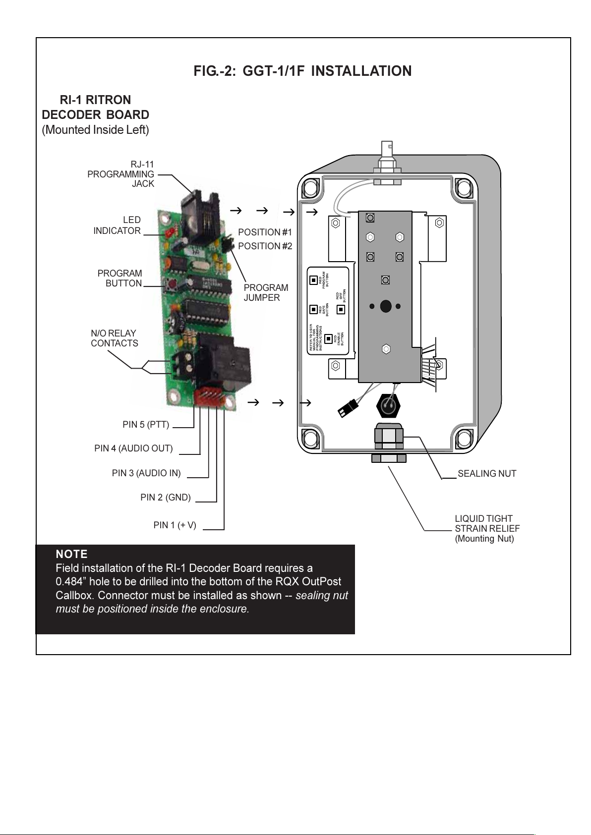
4. Route all wires through the provided strain relief at the bottom of the Callbox enclosure and any additional strain
relief or conduit. If the XT Model is being used, also route the wires through the drilled or punched hole and any
additional strain relief or conduit.
5. Connect the wire pair between the GateGuard normally open relay contact outputs (refer to FIG.2) and the
contact closure inputs on the device you wish to control.
6. Tighten all strain reliefs and any conduit junctions to ensure moisture/vandal resistance.
Step 5. - CALLBOX RE-ASSEMBLE  Basic and XT Models RQX-150/156/450/456/454
Standard Model: R X-150/156/450/456/454
1. Make sure power connectors between front and rear enclosures are connected.
2. Place front and rear enclosures together.
3. Tighten (4) large plastic screws. NOTE: DO NOT over-tighten, damage to screws may result.
4. Basic model - Attach message placard to front enclosure by lining up the push-button in the hole in the
placard and matching up the (4) Velcro pads on the back of the placard.
4. XT model  Place metal plate on outer enclosure.
5. XT model  Tighten (4) metal screws with Torx T-25 Tamper-proof screw bit.
Basic Ope ation - Model GGT-1/1F DTMF DECODER
The RITRON OUTPOST Radio Callbox with GateGuard installed will operate as such;
After a call has been initiated by the OutPost radio callbox, a two-way conversation can be established between
the callbox and a portable two-way radio. Likewise, personnel with a radio (portable, mobile or base station)
equipped with a DTMF keypad can transmit the access command code back to the OutPost callbox equipped
with a GateGuard decoder. By transmitting the correct GateGuard access command code via the radios keypad,
the user can now achieve long range, wireless remote control to activate motors, gates, locks, lights and/or pumps.
When the GateGuard decodes the correct access command code, the relay contacts will close momentarily (a
1/2-second) to control what has been connected to the relay contacts. The OutPost radio callbox will then
automatically transmit a short (1 second) acknowledgement tone back to the portable radio. This tone
acknowledgement in-turn alerts radio-equipped personnel that the OutPost callbox received and successfully
decoded the GateGuard access command code.
Note: Ackno ledgement Tone and Trunking Operation - If GateGuard is used ith a RITRON Model RQX-454/-XT
programmed for trunking mode through a repeater, the 1 second tone may be partially or entirely missed due to
Home Channel availability.
Rit on Quick Talk Wi eless Voice Ala m Repo te Offe s Wi eless Remote Monito ing
If you would like to know that the desired command was actually per ormed e.g. is the gate really moving?,
then Ritron has the perfect wireless solution for you. We recommend the uick Talk Wireless Voice Alarm
Reporter. The uick Talk R T-150/450/454 can be programmed to the radio system frequency and connected
to any switch i.e. a flex switch, magnetic reed switch, pressure plate etc.. in-turn this switch will be activated by
the actual opening/closing of the gate. A corresponding voice message is then transmitted via radio to all radio-
equipped personnel, providing confirmation on the status of the gate. This useful wireless device can be used in
conjunction with existing two-way radios  conventional, repeaters and UHF trunking system and a wide variety
of available switches or sensors.
The 1-second acknowledgement tone generated by the GGT-1 equipped Outpost indicates that a correct
access command code has been received and properly decoded. It does not confirm that the gate is actually
opening or closing; i.e., a damaged gate motor may not be operational. Even though a GateGuard equipped
OutPost callbox receives and decodes the signal, and the relay output closes, the attached device (e.g., a gate
opener) may not be operational. A uick Talk Voice Alarm Reporter along with a flex switch mounted in the path
of the gate will confirm via radio that the gate is actually moving. This added monitoring capability will also alert
radio-equipped personnel of unauthorized movement of the gate. Visit the Ritron web site at www.ritron.com or
call your dealer or Ritron at 800-USA-1-USA (800-872-1-872) for more information on the uick Talk Voice Alarm
Reporter.
All manuals and user guides at all-guides.com
FIG.-2: GGT-1/1F INSTALLATION
LIQUID TIGHT
STRAIN RELIEF
(Mounting Nut)
RI-1 RITRON
DECODER BOARD
(Mounted Inside Left)
SEALING NUT
NOTE
Field installation of the RI-1 Decoder Board requires a
0.484 hole to be drilled into the bottom of the RQ OutPost
Callbox. Connector must be installed as shown -- sealing nut
must be positioned inside the enclosure.
ggg
gg
gg
PIN 5 (PTT)
PIN 4 (AUDIO OUT)
PIN 3 (AUDIO IN)
PIN 2 (GND)
PIN 1 (+ V)
PROGRAM
BUTTON
LED
INDICATOR
RJ-11
PROGRAMMING
JACK
N/O RELAY
CONTACTS
PROGRAM
JUMPER
POSITION #1
POSITION #2
All manuals and user guides at all-guides.com
Installing the GGT-1F on an RQX XT-Series Callbox with Serial Number 13250 or Higher
1. Remove the four security screws from the front of
the XT case.
2. Lift off the faceplate and set it on the right side,
upside down.
3. Loosen the plastic case screws on the internal RQX
case and lift off the case lid.
4. Disconnect from the PCB:
•the phono plug for the antenna
•the battery plug
•the speaker cable
•the 6-conductor XT cable
5. Remove the PCB from the case front.
6. Solder the GGT-WH wire harness to the PCB using
the drawing below.
7. Re-install the PCB into the case.
8. Remove backing from tape on back of GGT board,
and press GGT to lower left side of battery plate.
9. Remove the blue and green wires from the XT cable
connector and strip the lead 3/8 inch.
10. Insert and secure the blue and green wires into the
relay contact terminals on the GGT-1F board.
11. Plug GGT-WH wire harness into GGT-1F board.
12. Reconnect to the PCB:
•the phono plug for the antenna
•the battery plug
•the speaker cable
•the 6-conductor XT cable
13. Close the unit, making sure not to pinch any wires
while closing the case.
14. Tighten the plastic case screws on the RQX case.
15. Re-install the metal faceplate.
Note: Drawing above for connection location only, the actually PCB may vary slightly from this drawing.
All manuals and user guides at all-guides.com
all-guides.com

This manual suits for next models

1

Other Ritron Media Converter manuals

Ritron LM-DTMF Installation manual

Ritron

Ritron LM-DTMF Installation manual

Ritron GateGuard GGT-1 DTMF Service manual

Ritron

Ritron GateGuard GGT-1 DTMF Service manual

Popular Media Converter manuals by other brands

B&B Electronics McBasic-Gigabit Operation manual

B&B Electronics

B&B Electronics McBasic-Gigabit Operation manual

Atlona AT-PRO130HD manual

Atlona

Atlona AT-PRO130HD manual

Cypress CLUX-UCEC Operation manual

Cypress

Cypress CLUX-UCEC Operation manual

Ensemble Designs BrightEye 91-A user guide

Ensemble Designs

Ensemble Designs BrightEye 91-A user guide

TANDBERG TT1200 MPEG2-DVB Installation and operator's manual

TANDBERG

TANDBERG TT1200 MPEG2-DVB Installation and operator's manual

Radi J-ISO user guide

Radi

Radi J-ISO user guide

SICK AHS36 IO-Link operating instructions

SICK

SICK AHS36 IO-Link operating instructions

CAKEWALK UM-2G owner's manual

CAKEWALK

CAKEWALK UM-2G owner's manual

SOUNDMASTER DAB950 instruction manual

SOUNDMASTER

SOUNDMASTER DAB950 instruction manual

Delta Tau ACC-28EP user manual

Delta Tau

Delta Tau ACC-28EP user manual

LDT Digital Professional Series Operating	 instruction

LDT

LDT Digital Professional Series Operating instruction

FOLSOM 2100DE Installation and operator's manual

FOLSOM

FOLSOM 2100DE Installation and operator's manual

Gefen EXT-DVI-2-MDP user manual

Gefen

Gefen EXT-DVI-2-MDP user manual

HEIDENHAIN AK ERP 10 Series Mounting instructions

HEIDENHAIN

HEIDENHAIN AK ERP 10 Series Mounting instructions

AVT MAGIC AE4 quick guide

AVT

AVT MAGIC AE4 quick guide

Wegener iPump615 Operator's manual

Wegener

Wegener iPump615 Operator's manual

ZENIC ForteVision FV-3000HS instruction manual

ZENIC

ZENIC ForteVision FV-3000HS instruction manual

Converters.TV Hand View III Operation manual

Converters.TV

Converters.TV Hand View III Operation manual

manuals.online logo
manuals.online logoBrands
  • About & Mission
  • Contact us
  • Privacy Policy
  • Terms and Conditions

Copyright 2025 Manuals.Online. All Rights Reserved.