Ritual Electronics Amnis User manual

Ritual Electronics
Gate IGate I
Gate IIGate II
Gate IIIGate III
Gate IVGate IV
Gate VGate V
Gate VIGate VI
Gate VIIGate VII
Gate VIIIGate VIII
Clock
Reset
Data
XOR
CV OddCV Odd
CV EvenCV Even
CV AllCV All
CV SlewCV Slew
Ritual
Electronics
Amnis
Amnis

2
Summary
03................Warranty
04................Installation
05................Overview
06................Controls
07................Shift Registers
08................Linear Feedback Shift Registers
09................Clock
10................Reset
11................Data
12................XOR
13................Outputs`
14................Expansion
15................Patch ideas

3
Amnis
Thank you for purchasing Ritual Electronics Amnis.
Your module has been assembled with care in our
studio in Marseille, France.
You can find your module on Modulargrid:
https://www.modulargrid.net/e/ritual-electronics-amnis
For any remarks and informations, contact us at:
For video demos and patch ideas check:
https://www.instagram.com/ritualelectronics/
Limited warranty
Ritual Electronics warrants this product to be free of defects in
materials or construction for a period of one year from the date
of purchase.
Malfunction resulting from wrong power supply voltages, backwards
or reversed eurorack bus board cable connection, abuse of the
product or any other causes determined by Ritual Electronics to be
the fault of the user are not covered by this warranty, and normal
service rates will apply.
During the warranty period, any defective products will be repaired
or replaced, at the option of Ritual Electronics, on a return-to-Ritual
Electronics basis with the customer paying the transit cost to Ritual
Electronics. The return of your module is on us.
Ritual Electronics implies and accepts no responsibility for harm to
person or apparatus caused through operation of this product.

4
Installation
Always turn your eurorack case off before plugging
or unplugging a module. Please pay attention to the
way you connect the bus board cable. Align the red
line on the cable with the “RED” text on the module.
Do not touch any electrical terminals when attaching any
Eurorack bus board cable.
Amnis uses a 10-pin cable for power. The bigger 16-pin
connector is used for expansions. See next page.
Ritual Electronics Amnis requires:
85mA on +12V (maximum recorded draw)
10mA on -12V
0mA on +5V
You will need 6HP of free space in your Eurorack case to
install Amnis. The module is 35mm deep.

5
Overview
Amnis is a shift register with a few tricks up its
sleeves. It can be used as a generative sequencer for
gates and CV, as a tunable digital noise source, as
a random gate and CV generator, as the center of a
chaotic system and more.
It needs two input signals to start doing its thing. A Clock
and some Data. Data can be pretty much any signals. Both
inputs are comparator-based.
From these two signals Amnis will generate 8 gate outputs,
always on the clock. From these gate outputs, it will
generate 3 staircase CVs and a slewed CV. With 8 gates
and 4 CV outputs it can be the heart of any patch.
Amnis has an XOR input for linear feedback. A shift register
with linear feedback is the core of the Rungler, the chaotic
core in Rob Hordijk’s Benjolin and Blippoo Box. With
Amnis you can recreate these type of behaviors with any
oscillators you have on hands. As it is fully patchable, you
can use the XOR for way more.
Amnis is compatible with the Turing Machine expanders
thanks to its expansion port at the back.

6
Gate Outputs
Individual gate outputs for each bit of
the shift register
0-8V range
Clock Input
Clocks the shift register
Comparator-based input
XOR Input
Second input of a dual input XOR gate
fed by the Data input
Comparator-based input
CV Odd
Staircase CV output resulting of all
odd gate outputs into an R-2R network
0-5V range
Reset Input
Empties the shift register when high
Comparator-based input, followed by a
gate to trigger converter
Data Input
Feeds values to the shift register
Comparator-based input
Amnis controls
Gate IGate I
Gate IIGate II
Gate IIIGate III
Gate IVGate IV
Gate VGate V
Gate VIGate VI
Gate VIIGate VII
Gate VIIIGate VIII
Clock
Reset
Data
XOR
CV OddCV Odd
CV EvenCV Even
CV AllCV All
CV SlewCV Slew
Ritual
Electronics
Amnis
CV Even
Staircase CV output resulting of all even
gate outputs into an R-2R network
0-5V range
CV All
Staircase CV output resulting of all
gate outputs into an R-2R network
0-5V range
CV Slew
Smooth CV output derived from the CV
all output
Approx. 0-5V range

7
Shift Registers
Digital shift registers were not created to be musical
devices. You can find a lot of them in computer
and digital devices were they can have a variety of
purposes. Despite being very simple it is as versatile
when used as part of a sound making system.
On each clock tick, the shift register reads the Data
input. If the Data input is High (signal above 2.5V)
the shift register will output a gate on Gate I output.
If the Data input is Low (signal below 2.5V) the shift
register won’t output a gate.
On the next clock tick, this process starts again. The
Data is analyzed and the result is outputed on Gate
I. At the same time the previous result gets shifted to
the next Gate output.
When the information reaches Gate VIII, it drops out
of the shift register and gets forgotten forever.
The Wikipedia article is not bad and worth reading
if you want to have a deeper understanding:
https://en.wikipedia.org/wiki/Shift_register
Do not mix up Shift Register and Analog Shift Register! The
latter is very different and while being very interesting in a
musical context, it is not what Amnis is. Amnis is a digital shift
register, it reads gates and outputs gates.
time
Gate I
Data
Clock
Gate II
Gate III
Gate IV
Gate V
Gate VI
Gate VII
Gate VIII

8
Linear Feedback Shift Registers
When coupled with a logic gate, shift registers can
turn into LFSRs or Linear Feeback Shift Registers. With
the use of feedback the shift register can be used to
generate pseudo-random sequences, digital noise
and more.
By connecting a Gate Output to the XOR Input of
Amnis, we create a feedback loop which influences
the result of the Data analysis. The Data signal will
be XORed against the the XOR Input. Note that
external signals can be used in the XOR Input.
A quick look at the Wikipedia article may confuse
you some more: https://en.wikipedia.org/wiki/
Linear-feedback_shift_register
In a musical context this means you can spice up the
sequences you get from the “classic” shift register.
You won’t get long non repeating random sequeces
with Amnis’ setup but using Gate VIII in the XOR
input you get a reasonnable amount of randomness.
By patching some more you can go very random
though. See the patch examples later.
time
Gate I
Data
XOR
Clock
Gate II
Gate III
Gate IV
Gate V
Gate VI
Gate VII
Gate VIII

9
Clock
The Clock system in Amnis deserves a bit of
explanation as it is a crucial element of the shift
register in a musical context.
The Clock and Data inputs need to be precisely
aligned to work as expected. If the Data signal is
received after the rising edge of the clock, it won’t
result in a High value at Gate I.
When Amnis Data source and the Clock originate
from the same digital source a problem can arise.
The digital nature of some sequencers for example
means the signal they output may have small timing
differences between them. The shift register does not
like this.
Amnis has a Clock delay built in to compensate for
this phenomenon. The trimmer on the bottom PCB is
used to shift the Clock forward in time. This way you
can align the Clock and the Data signals.
If you don’t plan on using Amnis this way, leave the
trimmer at 0 (fully CCW) as the delay compensation
reduces the maximum speed of the clock.
Let’s take a steady clock, 25% duty cycle. Let’s say we need to delay
it just a bit to align with the Data signal
As you move the threshold trimmer the beat will be delayed in time
The more you increase the threshold the more delayed your clock will
be.

10
Reset
The Reset Input can be used to create shorter
sequences or to empty the shift register bits
As all other inputs the Reset Input can be driven with
any signals thanks to its bult-in comparator.
It also features a gate to trigger convertor. This way
only the rising edge of the signal is used to reset
instead of pausing the shift register for the length of
the received gate.

11
Data
Data is a vague name for an input but we could not
find better. First, it shows the digital nature of the
shift register. Second, it does not specify the type of
expected signal... as it can be any!
It can be any signal but it will eventually end up
being a gate. The Data Input goes straight into a
comparator. Its threshold is set to 2.5V.
If the Data signal you use is correlated to the Clock
Input, you’ll have more or less repetitive behaviors.
If the Data signal is free running, completely
desynchronized, you’ll end up with an evolving
behavior.
For more control over the Data, use an external
comparator before the Data Input! As the Shift
Register cares only about gates, a voltage controlled
comparator (as our own Répression) to vary the gate
size is a must for more control and variations.

12
XOR
As described earlier, the XOR Input is used to turn
the shift register in a Linear Feedback Shift Register.
Musically, it allows multiple things.
The most straight forward is to add randomness or
variations to the shift register.
It can also be used to loop the register. For an 8-step
loop, plug Gate VIII to the XOR Input, disconnect
the Data cable when you like a sequence. Amnis
will repeat itself. See patch examples for a detailed
explanation.
If you have other logic modules in your system you
can try combining them with the Gate Outputs to
allow longer pseudo random sequences.
If you feed Amnis a single Gate in the Data input
and XOR together Gates IV, V, VI & VIII you will have
a 255 steps random sequence a.k.a. the longest
pseudo random sequece you can obtain with an 8-bit
linear feedback shift register.
A [Data] B [XOR] Out [Gate I]
0 0 0
1 0 1
0 1 1
1 1 0
XOR logic truth table
(0 = Gate Low, 1 = Gate High)
If a gate is present at both the Data input and the XOR input, the result will be
inverted
13
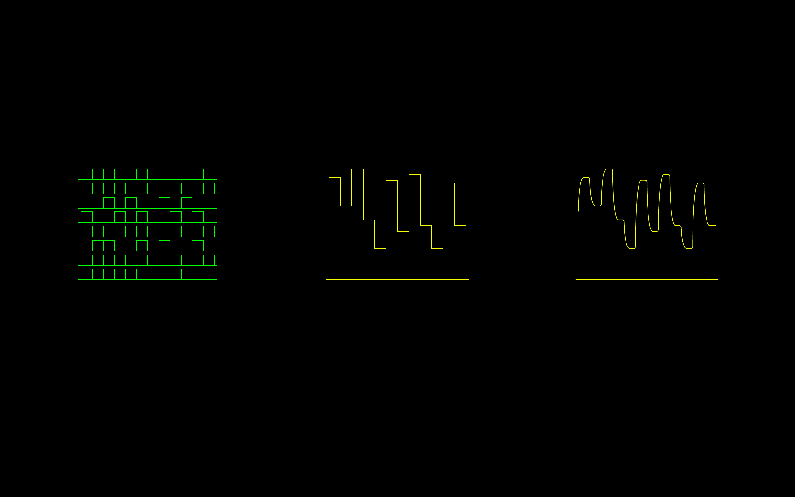
Outputs
Amnis has three type of outputs. 8 Gate outputs, 3 staircase CV outputs and 1 smooth CV output.
Gate Outputs
They correspond to each bit of the
register (bit 0 = Gate I, bit 1 = Gate
II, ..., bit 7 = Gate VIII)
They are 8V gates with a duty cycle
of 50% of the Clock
Staircase CV Outputs
The different CV outputs are mixed
together using the R-2R principle.
The first output uses the 4 odd bits
in a R-2R
The second output uses the 4 even
bits in a second R-2R
The third output uses all the outputs
in a 8-bit R-2R network.
Slewed CV Outputs
To add even more versatility to
Amnis we turned the All Output into
a smooth CV by sending it to a slew
limiter. It softens the edges of the
staircase for a Slewed CV Output.
Note that the slewing is speed
dependent. Different clock speed
will lead to different degrees of
smoothness.

14
Expansion
Amnis is compatible with the Music Thing Modular
Turing Machine expanders. It acts as the Master
(replaces the Turing Machine).
Please be very careful with the header connection. Many
Turing Machine expanders are not protected against reverse
voltages.
The iconic Music Thing Modular Turing Machine and Amnis
are both based around a shift register. Even though two very
different modules, someone at Superbooth asked if I could
make Amnis compatible with the expander systems... And I
did, which is great to expand Amnis’ abilities.
Some of the expanders are very useful, such as the simple
Music Thing Volts, the great Mystic Circuits Leaves or the very
blinken lightsy Schreibmaschine Modular Brainiac and Binary.
POWER HEADER
Red stripe down
EXPANSION HEADER
Red stripe left
Back of the module

15
Patch ideas
Patch #1 - Shift register 101
The most basic patch to get thing running. A clock in Clock in.
Since the shift register only uses the rising edge of the clock,
a trigger is enough. An LFO in the Data input will take you a
long way already. With these 2 simple signals you already
have 8 gate outputs and 4 CV outputs going.
Patch notes
Anima, Ch.1 Trigger Out ------------ Amnis, Clock In
Anima, Ch. 2 Out ------------- Amnis, Data In
For nearly repeating patterns, try to match the speed of the clock with the speed
of the LFO. For evolving patterns chose unrelated speeds.
Using an LFO with control over the waveform let you dial in different patterns
without varying the speed.
Anima
Attack
Curve
Decay
_+
_+_+
_+_+_+
Attack
Curve
Decay
_+
Unipolar
Bipolar
Attack I Curve I
Out IOut IEOC IEOC I
Decay I
Gate I 1V/Oct I
Attack II Curve II
Out IIOut IIEOC IIEOC II
Decay II
Gate II 1V/Oct II
Gate IGate I
Gate IIGate II
Gate IIIGate III
Gate IVGate IV
Gate VGate V
Gate VIGate VI
Gate VIIGate VII
Gate VIIIGate VIII
Clock
Reset
Data
XOR
CV OddCV Odd
CV EvenCV Even
CV AllCV All
CV SlewCV Slew
Ritual
Electronics
Amnis

16
Patch ideas
Patch #2 - LFSR 101
One more cable than the last patch and you got yourself an
LFSR. By patching the last gate output to the XOR input, the
outcome of the shift register will be influenced by the result of
the last bit. See how it changes the gate sequences and CV
outputs. Now try other gates and observe the different level of
complexity/perceived randomness.
Patch notes
Anima, Ch.1 Trigger Out ------------ Amnis, Clock In
Anima, Ch. 2 Out ------------- Amnis, Data In
Amnis, Gate VIII ------------- Amnis, XOR In
At this point stackcables may come in handy.
Anima
Attack
Curve
Decay
_+
_+_+
_+_+_+
Attack
Curve
Decay
_+
Unipolar
Bipolar
Attack I Curve I
Out IOut IEOC IEOC I
Decay I
Gate I 1V/Oct I
Attack II Curve II
Out IIOut IIEOC IIEOC II
Decay II
Gate II 1V/Oct II
Gate IGate I
Gate IIGate II
Gate IIIGate III
Gate IVGate IV
Gate VGate V
Gate VIGate VI
Gate VIIGate VII
Gate VIIIGate VIII
Clock
Reset
Data
XOR
CV OddCV Odd
CV EvenCV Even
CV AllCV All
CV SlewCV Slew
Ritual
Electronics
Amnis

17
Patch ideas
Patch #3 - Gate sequencer expander
Amnis is useful to create more sequences out of existing
sequences. Since the clock does not have to be stable in order
for the module to operate, put a first gate sequence in the
Clock In. Put a second gate sequence in Data. You’ll have 8
related patterns at the gate outs.
Use a third sequence in the XOR input to see even more
changes or use one of Amnis’ gate for linear feedback.
A
B
C
D
4
5
6
1
12
XY
34
567 8
2
3
7
8
Gate IGate I
Gate IIGate II
Gate IIIGate III
Gate IVGate IV
Gate VGate V
Gate VIGate VI
Gate VIIGate VII
Gate VIIIGate VIII
Clock
Reset
Data
XOR
CV OddCV Odd
CV EvenCV Even
CV AllCV All
CV SlewCV Slew
Ritual
Electronics
Amnis
Patch notes
Gate sequencer, Ch.1 Gate Out ------------ Amnis, Clock In
Gate sequencer, Ch. 2 Gate Out ------------- Amnis, Data In
Gate sequencer, Ch. 3 Gate Out ------------- Amnis, XOR In
Small changes in the initial sequences can have huge impact on the resulting
sequences!

18
Patch ideas
Patch #4 - True Clocked Random Generator
White Noise is real random in the analog world. Use it as a
source for real random, but clocked gates.
Use a comparator between the noise source and Amnis to
vary the density of the gates (the lower the threshold the more
gates will fire).
Gate IGate I
Gate IIGate II
Gate IIIGate III
Gate IVGate IV
Gate VGate V
Gate VIGate VI
Gate VIIGate VII
Gate VIIIGate VIII
Clock
Reset
Data
XOR
CV OddCV Odd
CV EvenCV Even
CV AllCV All
CV SlewCV Slew
Ritual
Electronics
Amnis
Répression
In
Thrsh CV
Threshold
Ritual Electronics
Above Bipolar
Below Equal
WhiteH iss
Pink Rumble
Krach
Patch notes
Gate sequencer, Ch.1 Gate Out ------------ Amnis, Clock In
Gate sequencer, Ch. 2 Gate Out ------------- Amnis, Data In
Gate sequencer, Ch. 3 Gate Out ------------- Amnis, XOR In
Go full on crazy random with noise outputs as Clock, Data and XOR! Or don’t.

19
Patch ideas
Patch #5 - Digital Noise & 1bit arpeggios
Another approach to Amnis and noise is to see it as a digital
noise generator. It is the first patch with Amnis running at
audio rate. Use an audio rate oscillator Clock, another
oscillator in Data, patch Gate VIII in XOR and take your audio
output from one of the gates.
As you slow down the Data oscillator from audio rate to LFO
you will enter arpeggios and 1bit computer glory.
Patch notes
Oscillator I, Out ------------ Amnis, Clock In
Oscillator II, Out ---------- Amnis, Data In
Amnis, Gate VIII ------------- Amnis, XOR In
Amnis, Gate n ------------- Output
Try different gate outputs for different sounds.
Use the Clock oscillator to tune your noise.
This patch is great at doing claps and cymbals!
Anima
Attack
Curve
Decay
_+
_+_+
_+_+_+
Attack
Curve
Decay
_+
Unipolar
Bipolar
Attack I Curve I
Out IOut IEOC IEOC I
Decay I
Gate I 1V/Oct I
Attack II Curve II
Out IIOut IIEOC IIEOC II
Decay II
Gate II 1V/Oct II
Gate IGate I
Gate IIGate II
Gate IIIGate III
Gate IVGate IV
Gate VGate V
Gate VIGate VI
Gate VIIGate VII
Gate VIIIGate VIII
Clock
Reset
Data
XOR
CV OddCV Odd
CV EvenCV Even
CV AllCV All
CV SlewCV Slew
Ritual
Electronics
Amnis

20
Patch ideas
Patch #6 - Rungler
A chaotic principle theorized by Rob Hordijk (thank you for all
the inspiration, RIP master) which uses the LFSR principle in a
feedback loop with two oscillators.
Add in a beautifully wet filter and you have yourself a
Benjolin.
A lot of fun can be had by rungling everything. Pick your
favorite dual oscillator, your favorite filter and rungle away.
This small patch will get you there but if you have a
comparator and a S&H on hand you can get closer to the
original Blippoo Box flavor. See OG flow chart here
Patch notes
Oscillator I, Out ------------ Amnis, Clock In
Oscillator II, Out ---------- Amnis, Data In
Oscillator I, Out ------------- Oscillator II, FM In
Oscillator II, Out ------------- Oscillator I, FM In
Oscillator I, Out ------------- Filter, In
Amnis, CV Odd Out ----------- Oscillator I, FM In
Amnis, CV Even Out ----------- Oscillator II, FM In
Amnis, CV All ------------ Filter, FM In
Amnis, Gate VIII Out ---------- Amnis, XOR In
Frequency 1
FM BusExponential FM
Linear FM
Exponential FMMod Bus Folder
Shape
Angle
Linear FM
Frequency 2
Expo Index CV
Lin
1V/Oct Lin
E
xpo 1V/Oct Folder CV
M
o
d
C
V
_+_+_+
_+
_+
Fo lded
Shape CV
Angle CV
Gate I
Gate I
Gate II
Gate II
Gate III
Gate III
Gate IV
Gate IV
Gate V
Gate V
Gate VI
Gate VI
Gate VII
Gate VII
Gate VIII
Gate VIII
Clock
Reset
Data
XOR
CV Odd
CV Odd
CV Even
CV Even
CV All
CV All
CV Slew
CV Slew
Ritual
Electronics
Amnis
_+
_+
_+
Out
Out
1V/Oct
Freq CV
In I In II
Table of contents


