Rivacold RCMR 350 User manual

RCMR Rev 02 02 13
UK
A
O
CC
EEIILLIINNGGCCUUBBIICCUUNNIITTCCOOOOLLEERRSS
P
I
IS
ST
TR
RU
UZ
ZI
IO
ON
NI
I
P
PE
ER
R
L
L’
’A
AS
SS
SE
EM
MB
BL
LA
AG
GG
GI
IO
O
A
AS
SS
SE
EM
MB
BL
LY
Y
I
IN
NS
ST
TR
RU
UC
CT
TI
IO
ON
NS
S
I
IN
NS
ST
TR
RU
UC
CT
TI
IO
ON
NS
S
D
D’
’A
AS
SS
SE
EM
MB
BL
LA
AG
GE
E
I
IN
NS
ST
TR
RU
UC
CC
CI
IO
ON
NE
ES
S
P
PA
AR
RA
A
E
EL
L
E
EN
NS
SA
AM
MB
BL
LA
AJ
JE
E
R
RC
CM
MR
R
Ø
Ø
3
35
50
0
-
-
4
45
50
0

RCMR Pag. 25 Rev 02 02 13
UK
Name of the Manufacturer: Rivacold s.r.l.
A
ddress:
V
ia Sicilia, 7
Fraz. Montecchio 61022 VALLEFOGLIA (PU)
Telephone: (+39) 0721 919911
Telefax: (+39) 0721 490015
Company RIVACOLD S.R.L. - All rights reserved
These assembly instructions are entrusted to the users of the CEILING CUBIC UNIT COOLERS RCMR mounted to instruct the technicians
appointed to installation and maintenance. The instructions, drawings, tables, and anything else contained in these instructions are of
reserved technical nature and cannot be reproduced and/or disclosed, neither entirely nor partially, without specific written
authorization by company RIVACOLD S.R.L.
It is explicitly forbidden to the technicians appointed to installation and maintenance to divulge the information contained in the
instructions and to use them for purposes other than those strictly tied to the good preservation of the CEILING CUBIC UNIT COOLERS
RCMR.
Company RIVACOLD S.R.L. cannot be held responsible or prosecuted for damages caused by an improper use of the documentation. In
order to avoid incorrect maneuvers that could cause danger to persons, it is important to read and understand the entire
documentation supplied with the CEILING CUBIC UNIT COOLERS RCMR.
INDEX
1 General information
1.1 General details
1.2 Conventions and Definitions
1.3 Warranty
1.4 Assistance
Pag 26
Pag 26
Pag 26
Pag 27
Pag 28
2 Description of the partly completed machinery Pag 28
3 Safety and Technical Data
3.1 General details on Safety
3.2 Devices and Solutions for Protection
3.3 Warnings concerning Residual risks
3.4 Signs concerning Safety
3.5 Proper and improper use of the partly completed machinery
3.6 General Warning and Behavioral Norms
3.7 Data and technical characteristics of partly completed machinery
3.8 Technical data
Pag 28
Pag 28
Pag 29
Pag 29
Pag 31
Pag 31
Pag 32
Pag 33
Pag 33
4 Transport and installation
4.1 General details
4.2 Transport and handling
4.3 Installation
4.4 Storage
4.5 Dis-installation
Pag 33
Pag 33
Pag 34
Pag 34
Pag 41
Pag 41
5 Maintenance and Demolition
5.1 General maintenance details
5.2 Sign concerning Safety
5.3 Checking material availability
5.4 Maintenance and cleaning
5.5 Disassembly and demolition
Pag 41
Pag 41
Pag 42
Pag 42
Pag 42
Pag 43
6 Optional feature Pag 44
7 search for Faults Pag 44
8 Drawings and technical characteristics
8.1 Diagram for removal of panels and motors
Pag 45
Pag 45
Technical and constructional characteristics of the RCMRØ350
Technical and constructional characteristics of the RCMRØ450
Pag 93
Pag 95

RCMR Pag. 26 Rev. 02 02 13
UK
1
1.
.
G
Ge
en
ne
er
ra
al
l
I
In
nf
fo
or
rm
ma
at
ti
io
on
n
1.1 General details
These assembly instructions are an integral part of the C
EILING CUBIC UNIT COOLERS
RCMR (which are identified in this document with the
term
PARTLY COMPLETED MACHINERY
) manufactured by company R
IVACOLD S
.
R
.
L
.; for this reason, they must be part of the technical file of
the final machine into which this
PARTLY COMPLETED MACHINERY
will be incorporated.
These instructions have been prepared with the purpose of providing to the technicians appointed to installation and maintenance of
the
PARTLY COMPLETED MACHINERY
the information and instructions that are essential to properly operate in safe conditions.
ATTENTION: because they must be easily and readily available to be consulted, these instructions must be kept
in a known and accessible place.
NOTE: The Purchaser can request copy of this document (for example, in case the original gets damaged)
in written form to the Technical Office of the Manufacturer (see Paragraph 1.4.1 – Request for
Assistance in this Chapter on the matter), undertaking commitment, at any rate, to return the
damaged copy.
1.2 Conventions and Definitions
1.2.1 General details
The assembly instructions of the
PARTLY COMPLETED MACHINERY
have been divided into chapters which allow the reader, for each phase of
the lifetime of the
PARTLY COMPLETED MACHINERY
(transport, installation, maintenance, and dismissal), to make it simple to find the relative
information necessary to the User of the
PARTLY COMPLETED MACHINERY
.
The entire documentation relative to the
PARTLY COMPLETED MACHINERY
has been prepared developing the themes indicated by Machines'
Directive (2006/42/CE), by the PED Directive (97/23/CE), and by the safety Norms in force.
The configuration of certain components or devices described or depicted in the documents may differ from the one with which the
PARTLY COMPLETED MACHINERY
is equipped in its specific set-up made according with particular safety requirements or norms; in such
case, certain descriptions, references, or recommended procedures may have a general character, though preserving their efficacy.
Quoted drawings and photographs are provided as mere examples, to serve as references for a smoother comprehension of the text.
1.2.2 Terminological conventions
PARTLY COMPLETED MACHINERY
: the term used in these assembly Instructions to refer to the C
EILING CUBIC UNIT COOLERS
RCMR.
IPD: the acronym that stands for Individual Protection Device(s).
1.2.3 Definitions
D
ANGEROUS AREA
Any
AREA
near the
PARTLY COMPLETED MACHINERY
in which the presence of an exposed person represents a risk to the safety and health of
that very person.
U
SER
Any
PERSON
(entrepreneur/company) who adequately uses the machine on which this
PARTLY COMPLETED MACHINERY
is installed, or who
entrusts its use or operations related to its use to prepared persons.
E
XPOSED PERSON
Any
PERSON
who happens to be entirely or partially in a dangerous area or near such an area.
M
ECHANICAL MAINTENANCE WORKER
QUALIFIED TECHNICIAN
who can intervene on any mechanical component to perform the necessary adjustments, repairs, and
maintenance interventions.
The mechanical maintenance worker is usually not licensed to perform interventions on electrical systems in the presence of voltage.
E
LECTRICAL MAINTENANCE WORKER
QUALIFIED TECHNICIAN
who is responsible for all interventions of electrical type (adjustment, maintenance, and repair) and who, when
necessary, operates in the presence of voltage inside the electrical cabinets and shunt boxes.
P
ERSONNEL APPOINTED TO
H
ANDLING
QUALIFIED PERSONNEL
who performs the tasks of handling the
PARTLY COMPLETED MACHINERY
or the materials used, were the operation to
require the use of lifting devices.
T
ECHNICIAN OF THE
M
ANUFACTURER
QUALIFIED TECHNICIAN
made available by the Manufacturer of the
PARTLY COMPLETED MACHINERY
to carry out complex operations in special
circumstances or, at any rate, agreed with the user.
1.2.4 Individual Protection Devices and Behavioral Norms
The protective devices that the appointed personnel is responsible to use, and the behavioral norms that allow the operators to be
properly safeguarded, are indicated for each of the operations described in these instructions.
NOTE: Paragraph 3.6 – General Warnings and Behavioral Norms in Chapter 3 – Safety and Technical
Data, in particular, reports a series of general recommendations to follow in order to avoid
conditions of risk to persons or of damages to the
PARTLY COMPLETED MACHINERY
.

RCMR Pag. 27 Rev. 02 02 13
UK
1.2.5 Typographical conventions
The graphic layout of these assembly instructions is such that it allows the reader to easily recognize the contents; with this mindset, for
example, the instructions are associated to lists, as indicated below:
this symbol identifies a generic bulleted list or one formed by simple actions (the order in which the actions are listed is not
mandatory, but highly recommended);
1. this symbol is used to identify a numbered list that explains a complex procedure (the order in which the actions are listed is
mandatory in order to properly and safely perform the intervention being examined).
The text in Italics is, in particular, used for:
cross-references; the cross-references used in these instructions are expressed in the following form: “Paragraph/Figure/Chart"
with the number and, usually, the specification "in the Chapter", with the number and relative title (when the Chapter is not
specified, it is understood that the paragraph, chart, or figure belong to the current one);
the technical and specialist terms, the first time they appear in the text;
the terms in a foreign language that are of common use (these too, usually, only the first time they appear in the text).
The bold text is used to highlight words, sentences, or parts of a procedure.
Moreover, to ensure an in-depth knowledge of the
PARTLY COMPLETED MACHINERY
, the text of these assembly instructions is accompanied
by indications that complete them, providing supplementary information, essential cautions, or especially significant dangers that need
to be considered; the following notation is used in this regard:
NOTE: indicates the notes, cautions, suggestions, and other points to which the reader's attention wants to
be recalled, or otherwise completes the explanation with added information.
ATTENTION: indicates situations or operations which entail the possibility of causing damage to the
PARTLY
COMPLETED MACHINERY
, the equipment connected to it, or to the environment.
DANGER: indicates situations or operations that absolutely must be performed, or the information to which
special attention must be given, to avoid damages to persons.
Graphic symbology adopted to indicate the Need for Individual Protection Devices
The graphic symbols used in these instructions to address the need to wear certain specific IPD are indicated in this paragraph.
Indicates the need to use protections for the head suitable to perform the operation described.
Indicates the need to use protective gloves suitable to perform the operation described (if need
be, dielectric gloves when executing interventions on the electrical system).
Indicates the need to use protective clothing suitable to perform the operation described.
Indicates the need to use anti-injury boots suitable to perform the operation described.
1.3 Warranty
1.3.1 General conditions
The Manufacturer, company R
IVACOLD S
.
R
.
L
., guarantees that the
PARTLY COMPLETED MACHINERY
and the equipment produced by the
Manufacturer are free of material and processing flaws, for a period agreed upon stipulation of the sale contract of the very
PARTLY
COMPLETED MACHINERY
.
1.3.2 Parts excluded from the Warranty
The pieces prone to wear & tear and all the tools and consumption materials possibly supplied by the Manufacturer along with the
PARTLY COMPLETED MACHINERY
are excluded from the warranty.

RCMR Pag. 28 Rev. 02 02 13
UK
1.3.3 Operations that entail Expiry of the Warranty
Any attempt to disassemble, modify, or tamper with a component of the
PARTLY COMPLETED MACHINERY
made by the User or by
unauthorized personnel entails expiry of the warranty and absolves the Manufacturer of any responsibility concerning any possible
damages to persons and things a like that stem from such tampering.
The Manufacturer likewise deems itself absolved of any possible responsibility and cancels the warranty on the
PARTLY COMPLETED
MACHINERY
in the following circumstances:
unforeseen use of the
PARTLY COMPLETED MACHINERY
(in this respect, see Paragraph 3.5 – Proper and improper use of the
PARTLY
COMPLETED MACHINERY
in Chapter 3 – Safety and Technical Data);
use contrary to what established by the norms in force in the country where the machine is being used;
installation of the
PARTLY COMPLETED MACHINERY
in conditions differing from those specified in Chapter 4 – Transport and
Installation;
installation not compliant to the specifications reported in Chapter 4 – Transport and Installation;
total or partial inobservance of the instructions reported herein;
failure to perform or improper maintenance;
use of non-original spare parts or ones not specified by the Manufacturer.
1.4 Assistance
With regard to the maximum exploitation of the performances provided by the
PARTLY COMPLETED MACHINERY
and extraordinary
maintenance operations, these instructions do not replace the experience of the trained and qualified installers, users, and
maintenance workers.
In the case in point, the Technical Assistance Service of company R
IVACOLD S
.
R
.
L
. provides:
support over the phone concerning the characteristics and most simple interventions that can be performed on the
PARTLY
COMPLETED MACHINERY
;
forwarding of documentation;
ATTENTION: in case of doubts on how to correctly interpret the instructions reported in these assembly
instructions, consult the Technical Assistance Service (in the manner indicated below) to obtain the
NECESSARY
clarifications.
1.4.1 Request for Assistance
To speak with the Technical Assistance Service, contact:
T
ECHNICAL
O
FFICE OF THE COMPANY
R
IVACOLD S
.
R
.
L
.
Via Sicilia, 7
Fraz. Montecchio 61022 VALLEFOGLIA (PU)
I
TALY
Telephone: (+39) 0721 919911
Telefax: (+39) 0721 490015
When requesting the intervention of the assistance service, specify the name, model, and serial number of the
PARTLY COMPLETED
MACHINERY
.
2
2.
.
D
De
es
sc
cr
ri
ip
pt
ti
io
on
n
o
of
f
t
th
he
e
p
pa
ar
rt
tl
ly
y
c
co
om
mp
pl
le
et
te
ed
d
m
ma
ac
ch
hi
in
ne
er
ry
y
The
PARTLY COMPLETED MACHINERY
discussed in this document is an
air-cooled evaporator designed and manufactured to be
incorporated in a refrigerating circuit arranged by the customer.
The
PARTLY COMPLETED MACHINERY
is available in different versions,
depending on the diameter of the fan motors; more specifically,
there are models with fan motors that have a diameter of 350 and
450 mm. All the versions are available with (ED models) or without
a defrosting heater.
Regardless of the configuration, at any rate, the
PARTLY COMPLETED
MACHINERY
is supplied without a control or power logic, because it
must be inserted in the refrigerating circuit arranged by the
customer. This is why it represents a
PARTLY COMPLETED MACHINERY
, as
defined by Machines' Directive 2006/42/CE: because it is not
capable of carrying out a well-defined application (without being inserted in a refrigerating circuit and without having a control or
power logic, it cannot perform the function for which it is manufactured). It can freely circulate on the market, because it is
accompanied by a correspondent declaration of incorporation by the manufacturer and by the correspondent assembly instructions,
that allow its simple integration in the final machine (which will then have to be marked CE, pursuant to the directives applicable to it,
by the subject making the integration).

RCMR Pag. 29 Rev. 02 02 13
UK
3.Safety and Technical Data
3.1 General details on Safety
3.1.1 Engineering Criteria
When engineering the
PARTLY COMPLETED MACHINERY
, the principles and concepts have been adopted, introduced by the pertinent
paragraphs of the harmonized norms indicated in Chart 1.
Chart 1 – Main harmonized norms used when engineering the
PARTLY COMPLETED MACHINERY
.
NORM TITLE
UNI EN ISO
12100: 2010 Safety of the machinery - General engineering principles – Evaluation of the risk and
reduction of the risk
UNI EN ISO
13857: 2008 Safety of the machinery - Safety distances to prevent upper and lower limbs from accessing
dangerous areas
UNI EN
953: 2009 Safety of the machinery - General requirements for the engineering and construction of
guards (fixed, mobile)
UNI EN
378-1:
2011 Refrigeration systems and heat pumps – Safety and environmental requirements – Part 1:
basic requirements, definitions, classification, and selection criteria
UNI EN
378-2:
2009 Refrigeration systems and heat pumps – Safety and environmental requirements – Part 2:
engineering, construction, tests, marking, and documentation
The observance of the pertinent paragraphs of the aforementioned harmonized norms has allowed us to eliminate or reduce the risks
as best as possible, both during standard machine operation and during maintenance operations.
The components used have been accurately selected among those available on the market, and the materials that make up the
PARTLY
COMPLETED MACHINERY
are void of risks to the health and safety of persons. All the parts supplied by third parties are marked
CE
(when
required) and are compliant with the relative directives of reference. All the details have been severely checked, in compliance with the
quality standards provisioned by the norms in force.
For the
PARTLY COMPLETED MACHINERY
, moreover, the necessary cautionary and protective measures have been adopted against residual
risks (in this respect, see Paragraph 3.3 - Warnings concerning Residual Risks).
3.2 Devices and Solutions for Protection
The devices and constructional solutions described below have been adopted on the
PARTLY COMPLETED MACHINERY
.
Fixed guards in steel sheet and protective grids near the mobile parts.
Safety signs near the fixed guards.
3.3 Warnings concerning Residual risks
In order to avoid any condition of danger to persons or of damages to the
PARTLY COMPLETED MACHINERY
caused by residual risks, in
other words, those risks that persist in spite of all the measures adopted, or caused by potential risks that are not readily apparent, the
Manufacturer recommends to the maintenance workers and all the personnel appointed to the
PARTLY COMPLETED MACHINERY
to
diligently follow the warnings indicated in the following pages.
ATTENTION: always follow the signals and the indications of the labels applied on the
PARTLY COMPLETED
MACHINERY
and exclusively operate based on the instructions provided herein (such as those
reported, for example, in Paragraph 3.6 - General Warnings and Behavioral Norms).
3.3.1 Lifting and Transport
3.3.1.1 Residual risks present during Lifting and Transport
There are risks during the lifting and transport phases tied to:
operations on the
PARTLY COMPLETED MACHINERY
by unqualified, untrained, uninformed, or improperly equipped personnel.
incorrect choice or incorrect use of devices to transport and handle (e.g., hoist, lift) the
PARTLY COMPLETED MACHINERY
;
crushing of the operators appointed to maintenance;
loss of load stability during the operations being examined;
projection of mobile parts of the
PARTLY COMPLETED MACHINERY
that cannot be appropriately removed or fastened;
collision of parts or components of the
PARTLY COMPLETED MACHINERY
with persons or things due to unexpected displacements of
the
PARTLY COMPLETED MACHINERY
itself or to improper behavior by personnel appointed to the operation;
collision or fall of component parts of the
PARTLY COMPLETED MACHINERY
which damage the
PARTLY COMPLETED MACHINERY
and its
relative protections;
unhealthy positions or excessive strain for the operators appointed to transport and handle the components of the
PARTLY
COMPLETED MACHINERY
.
3.3.1.2 Necessary Individual Protection Devices

RCMR Pag. 30 Rev. 02 02 13
UK
3.3.1.3 Cautions to be followed during Lifting and Transport
During the lifting and transport phases, the cautions described in this paragraph must be followed.
For these operations, only designate specialized personnel trained concerning the procedures to handle machineries and
capable of choosing and safely using the lifting and transport devices most suitable to the given circumstance (e.g. hoist, lifts).
Check and, if need be, make sure that all the parts that can move are properly fastened (or, if required, removed and
reassembled when the operation is completed).
Do not for any reason whatsoever lift the various parts of the PARTLY COMPLETED MACHINERY by grabbing it by its non-structural
elements (e.g. wires or sheaths).
Make sure there are no persons near the area where the lifting, handling, and unloading operations are taking place, and
always keep at a safety distance.
Always pre-alert that maneuvers are about to commence.
Do not transit beneath hanging loads.
Do not let yourself be transported together with the loads.
3.3.2 Installation and Hook-up
3.3.2.1 Residual risks present during Installation and Hook-up
There are risks during the installation and hook-up phases tied to:
operations on the PARTLY COMPLETED MACHINERY by unqualified, untrained, uninformed, or improperly equipped personnel.
contact with elements under voltage;
collision or crushing by components of the PARTLY COMPLETED MACHINERY being handled;
tripping or falling near electrical power connections;
damage of the PARTLY COMPLETED MACHINERY during the installation and hook-up phases.
3.3.2.2 Necessary Individual Protection Devices
3.3.2.3 Included warning signs
The PARTLY COMPLETED MACHINERY is equipped with specific danger and prohibition signs; in this respect, see Paragraph 3.4 - Signs
concerning Safety.
3.3.2.4 Cautions to be followed during Installation and Hook-up
During the installation and hook-up phases, the cautions described in this paragraph must be followed.
Follow the indications relative to safety reported in Paragraph 3.3.1 - Lifting and Transport during the necessary handling
operations on the PARTLY COMPLETED MACHINERY .
Use the auxiliary equipment and, at any rate, any other machinery or tool (electrical or pneumatic) only after having understood
the indications reported in the relative Use and Maintenance Manuals, or after having undergone specific and formal training.
Protect the piping of the connections to the energy sources with rigid sheaths or adequate wire feed-thru conduits.
Perform the required interventions using work tools up to norm (ladders, various tools) and paying utmost attention to elements
that could lead to tripping or cause cuts and contusions.
3.3.3 Maintenance and Demolition
3.3.3.1 Residual risks present during Maintenance and Demolition
There are risks during the maintenance and demolition phases tied to:
operations on the PARTLY COMPLETED MACHINERY by unqualified, untrained, uninformed, or improperly equipped personnel.
collision and crushing by components of the PARTLY COMPLETED MACHINERY being handled;
contact with hot elements of the PARTLY COMPLETED MACHINERY or of the relative equipment;
contact with refrigerant fluid.
3.3.3.2 Necessary Individual Protection Devices
3.3.3.3 Included warning signs
The PARTLY COMPLETED MACHINERY is equipped with specific danger and prohibition signs; in this respect, see Paragraph 3.4 - Signs
concerning Safety.
3.3.3.4 Cautions to be followed during Maintenance and Demolition
During the maintenance and demolition phases, the cautions described in this paragraph must be followed.
Perform the required interventions using work instruments up to norm (ladders, various tools) and always wearing the necessary
IPD.
The maintenance and demolition interventions must be performed by qualified and specifically trained personnel.
Check that the power supplies have been duly disconnected and that no one can reactivate them before the required
interventions are concluded (need to act on the main on/off switch, supplied as a separate optional feature, of each fan motor;

RCMR Pag. 31 Rev. 02 02 13
UK
alternatively, disconnect the entire unit from the line provided by the customer); moreover, check that any possible residual
energy has been de-charged before performing the interventions.
As much as possible, operate on the PARTLY COMPLETED MACHINERY and on the piping only after having emptied them and, before
proceeding to restart it, make sure the system is thoroughly cleaned.
Obtain the necessary work permits and check that all the procedures to arrange the PARTLY COMPLETED MACHINERY for maintenance
operations have been performed correctly.
Do not for any reason whatsoever use gasoline, solvents, or flammable fluids to clean the details, but use standardly marketed
and approved detergents that are not flammable and toxic.
Do not perform modifications, transformations, or applications on the PARTLY COMPLETED MACHINERY which could jeopardize safety,
without first having obtained written authorization by the Manufacturer.
3.4 Signs concerning Safety
Signaling labels are affixed on the PARTLY COMPLETED MACHINERY that are indicated in Chart 2.
Chart 2 – Description of the warning labels affixed on the PARTLY COMPLETED MACHINERY.
LABEL DESCRIPTION
A
Indicates that it is forbidden to remove the safety devices and protections
installed; it is usually accompanied by the explanatory wording: DO NOT REMOVE
THE PROTECTIVE DEVICES.
B
Indicates that it is forbidden to perform any type of intervention (including
lubrication and cleaning) near moving parts; usually, it is accompanied by the
explanatory wording: DO NOT REPAIR OR ADJUST WHILE THE MACHINE IS RUNNING.
C
Warns about the danger due to the presence of mobile parts near the machine
area where it is positioned.
D
Warns about the danger due to the presence of hot surfaces near the machine
area where it is positioned.
E
Warns about the danger due to the presence of elements under voltage near the
machine area where it is positioned.
F
Signals that it is mandatory to read the manual / assembly instructions

RCMR Pag. 32 Rev. 02 02 13
UK
G
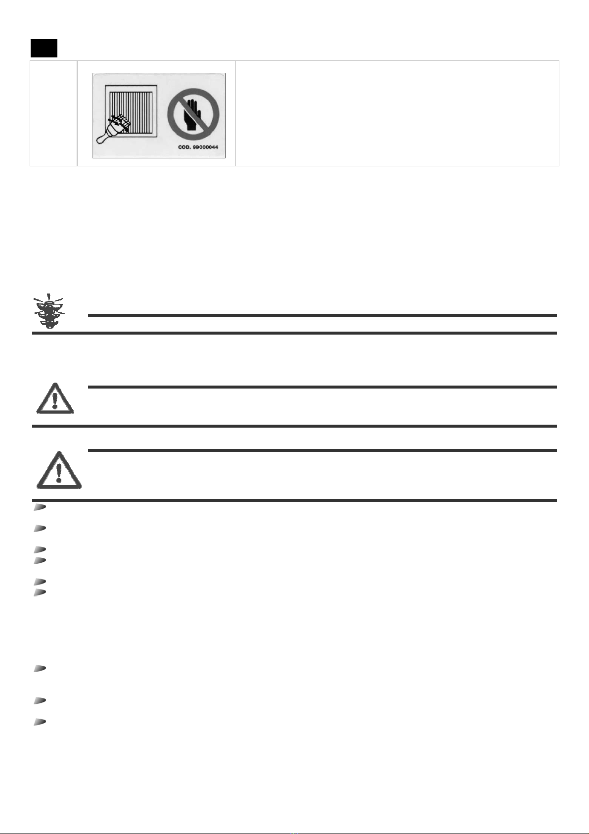
Be careful for sharp cutting parts and when cleaning the air-cooled evaporator
3.5 Proper and improper use of the partly completed machinery
The
PARTLY COMPLETED MACHINERY
is designed and built to be inserted in a refrigerating circuit that can be used in the field of industrial
and commercial refrigeration in a permanent site.
Each model of the
PARTLY COMPLETED MACHINERY
can make use of the refrigerant gas specifically foreseen and indicated on its plate.
The
PARTLY COMPLETED MACHINERY
has been designed and built to work in environments that do not have a potentially explosive
atmosphere.
It is a sound cautionary norm to place powder extinguishers near the
PARTLY COMPLETED MACHINERY
. To prevent the possibility of a fire
outbreak, it is necessary to keep the
PARTLY COMPLETED MACHINERY
clean of pieces of plastic, oils, solvents, paper, and rags.
The use of the
PARTLY COMPLETED MACHINERY
for different operations or the use of a refrigerant gas different from the one indicated on
the plate could cause damages to persons or to the
PARTLY COMPLETED MACHINERY
itself, and are therefore considered improper uses for
which the Manufacturer does not deem itself responsible.
ATTENTION: in case of a different intended use, it is essential to first consult the Technical Office of the Manufacturer.
3.6 General Warnings and Behavioral Norms
In order to avoid any condition of risk to persons or of damages to the
PARTLY COMPLETED MACHINERY
, we recommend that you diligently
follow the general warnings and behavioral norms reported herein.
DANGER: the Manufacturer rejects any responsibility for possible damages to things and/or persons
stemming from improper interventions performed by unqualified, untrained, or unauthorized
personnel.
The operators appointed to manage the
PARTLY COMPLETED MACHINERY
must be duly instructed on how to best use it risk-free, and must
operate in a comfortable environment that can ensure the best possible conditions of safety and hygiene.
DANGER: prevent that the
PARTLY COMPLETED MACHINERY
be used by unauthorized or uninstructed personnel
without surveillance: in fact, before starting to work, each operator must be perfectly
knowledgeable of the characteristics of the
PARTLY COMPLETED MACHINERY
; he must, moreover, have
FULLY
read these instructions.
Before using the
PARTLY COMPLETED MACHINERY
, make sure that any condition dangerous to safety has been duly eliminated and
that there are no operators in the dangerous areas near the
PARTLY COMPLETED MACHINERY
.
Before using the
PARTLY COMPLETED MACHINERY
, make sure that all the guards or other protections are in their place and that all the
safety devices are present and efficient.
After having removed the packing, make sure that all the parts of the machine are intact; if they are not, contact the retailer.
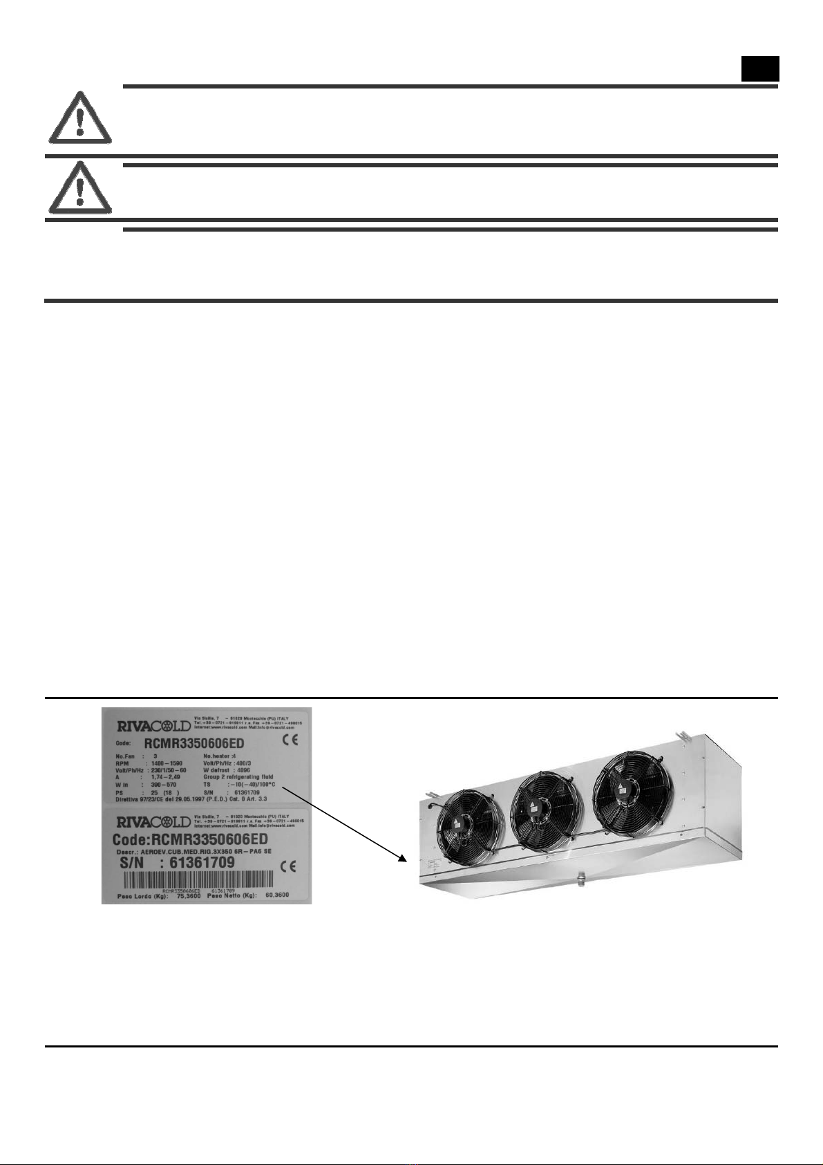
Carefully read the labels on the
PARTLY COMPLETED MACHINERY
, do not cover them for any reason, and immediately replace them if
they get damaged.
Do not lay liquid containers on the
PARTLY COMPLETED MACHINERY
.
Consult these instructions with regard to the safety provisions in force and to the specific IPD to be adopted for personal safety;
more specifically, at any rate, the personnel appointed to the
PARTLY COMPLETED MACHINERY
must wear suitable clothing, avoiding or
paying the necessary attention to:
flapping clothing,
loose sleeves,
dangling neckties or scarves,
necklaces, bracelets, and rings.
The personnel appointed to maintenance on the
PARTLY COMPLETED MACHINERY
must be knowledgeable of all the procedures
reported in Chapter 5 - Maintenance and Demolition and have adequate technical preparation to correctly interpret the
instructions and annexed diagrams and to intervene on the
PARTLY COMPLETED MACHINERY
.
The area where the maintenance operations are performed must always be clean, dry, and with the suitable equipment always
available and efficient.
In case it were necessary to perform interventions near electrical components, operate with thoroughly dried hands and use
dielectric gloves (operating on electrical components with wet hands may lead to a near certain danger of electrical shock):

RCMR Pag. 33 Rev. 02 02 13
UK
DANGER: it is necessary to make sure that before starting any type of intervention on the
PARTLY COMPLETED
MACHINERY
or near its components or accessory equipment, the power supply be cut-off; if this were
not possible, it is necessary to take measures that, at any rate, allow operators to safely work near
the
PARTLY COMPLETED MACHINERY
.
DANGER: unauthorized tampering with or replacement of one or more parts of the
PARTLY COMPLETED MACHINERY
and
the use of accessories, tools, and consumption materials different than those indicated by the Manufacturer
may cause danger of injury.
ATTENTION: all the materials with an environmental impact which need to be eliminated following interventions or
processing on the
PARTLY COMPLETED MACHINERY
must be disposed of in accordance with the norms in
force.
If necessary, contact specialized waste collection centers for their disposal.
3.7 Data and technical characteristics of the partly completed machinery
3.7.1 Identification plate
To identify the
PARTLY COMPLETED MACHINERY
, an identification plate has been affixed onto it (for example, in Figure 1); the identification
data reported on this plate must be notified to the offices of the Manufacturer upon each request for its intervention or when ordering
spare parts. More specifically, the following data are reported on the identification plate:
¾code,
¾no. of fan motors,
¾no of revs (RPM),
¾power supply voltage (Volt/Ph/Hz),
¾absorption in ampere (A),
¾absorption in Watt (W in),
¾maximum operating pressure (PS),
¾refrigerant fluid unit: Unit 2
¾minimum/maximum operating temperature (TS),
¾serial number.
¾system category according to Directive 97/23 / EC (PED).
Defrosting heaters are included on the ED models; in this case, the plate also reports the following information:
¾no. of heaters,
¾absorption in Watt (W defrost),
¾power supply voltage (Volt/Ph/Hz).
Breakdown of the serial number
¾digits 1 and 2 = code that identifies the year of manufacture,
¾digits 3 and 4 = week of the year in which the
PARTLY COMPLETED MACHINERY
was manufactured,
¾digits 5, 6, 7, and 8 = progressive number.
Figure 1 – Identification plate.
3.8 Technical data
All the air-cooled evaporators are equipped with axial fan motors that are not suited for additional prevalence.
The heat exchanger is in copper-aluminum, and therefore not suitable to be used in aggressive environments.
The guarding is made of aluminum. The screws, washers, and nuts are in stainless steel. The air-cooled evaporators are equipped
with axial fan motors powered with 230/1/50-60Hz. The main characteristics of the
PARTLY COMPLETED MACHINERY
can be found in
Chapter 8 of these instructions.
4
4.
.
T
Tr
ra
an
ns
sp
po
or
rt
t
a
an
nd
d
i
in
ns
st
ta
al
ll
la
at
ti
io
on
n
4.1 General details
The installation of the
PARTLY COMPLETED MACHINERY
is directly performed by qualified personnel.

RCMR Pag. 34 Rev. 02 02 13
UK
Before proceeding to incorporate the
PARTLY COMPLETED MACHINERY
into the final machine, you must, however, arrange the power
supplies and the utilities necessary for the system to operate properly, following the indications reported in this Chapter and, if
necessary, consulting the Technical Office of the Manufacturer first.
ATTENTION: the user, once the equipment has been purchased and before its use, becomes responsible for the
component, subjected to Directive 97/93/CE (PED), and must perform the inspections by law in
accordance with the national legislature in force (M.D. 329 dated 1/12/2004 for Italy). E.g. notification of
putting into service, periodical inspection, etc.
DANGER : the Manufacturer rejects any responsibility for possible damages to things and/or persons
stemming from improper interventions performed by unqualified, untrained, or unauthorized
personnel.
4.1.1 Power supplies and Utilities
The power supplies and utilities necessary (responsibility of the Purchaser) for the
PARTLY COMPLETED MACHINERY
to operate, exclusively
consist in the supply of electrical energy.
Unless otherwise specified, the following remain responsibility of the Purchaser:
arranging the transport devices necessary to transport the
PARTLY COMPLETED MACHINERY
to the premises where it is to be assembled
or installed;
arranging the tools necessary for assembly and installation;
arranging the auxiliary devices and consumption materials (e.g. non-flammable and rustproof detergents, materials and tools
necessary for cleaning, and covering cloths).
4.2 Transport and handling
The indications contained in this paragraph must be followed when transporting and handling the
PARTLY COMPLETED MACHINERY
,
indications which may occur during the procedure to install the
PARTLY COMPLETED MACHINERY
on the final machine.
DANGER : the Manufacturer rejects any responsibility for possible damages to things and/or persons
stemming from improper interventions performed by unqualified, untrained, or unauthorized
personnel.
The following Individual Protection Devices are necessary to perform the task being examined:
When transporting or handling the
PARTLY COMPLETED MACHINERY
, it is necessary to follow the cautions described below:
Check that the lifting equipment is suitable to the weight and size of the
PARTLY COMPLETED MACHINERY
.
Do not bump with equipment or anything else against the structure or the protections of the
PARTLY COMPLETED MACHINERY
.
The air-cooled evaporator is supplied sealed within cardboard boxes with inner wooden supports, except RCMR345_/ED and
RCMR445_/ED supplied sealed within cardboard boxes with inner wooden supports.
4.2.1 Lifting
DANGER : the lifting operations must be performed under the direct supervision of a qualified mechanical
maintenance worker.
The lifting operations to handle and then position the
PARTLY COMPLETED MACHINERY
can be performed with any adequate device that
guarantees and effective and safe lift.
To properly perform the lifting operations, follow the cautions reported below.
Never use two lifting devices at the same time.
Do not station beneath hanging loads.
If steel ropes are used, always keep an eye on the eyelet of the end of the lifting hook.
If steel ropes are used, be careful not to form harsh folds, in other words, with a curvature radius smaller than the one of the
eyelets of the rope ends.
The use of a lifting bar is recommended with certain models, in order to guarantee optimal distribution of the weights.
During the handling and installation phases, be careful not to damage the guarding and the fluid inlet/outlet collectors.
ATTENTION: throughout all of these operations, follow the precautions necessary to avoid collisions and tipping over,
handling the
PARTLY COMPLETED MACHINERY
so as not to lose balance.
DANGER : make sure there is no unauthorized personnel near the area where the lifting, handling, and
unloading operations are taking place, and always keep at a safety distance.

RCMR Pag. 35 Rev. 02 02 13
UK
4.3 Installation
DANGER : the Manufacturer rejects any responsibility for possible damages to things and/or persons
stemming from improper interventions performed by unqualified, untrained, or unauthorized
personnel.
The following Individual Protection Devices are necessary to perform the task being examined:
Before proceeding with the installation, a project of the refrigeration system must have been developed, which defines:
all the components of the refrigeration system (e.g. condensing unit, evaporator, thermostatic valve, electrical panel, piping size,
any possible safety components, etc.);
placement of the system;
path of the piping.
The unit must be exclusively installed with a ceiling mount. For other applications, consult the Technical Office of the Manufacturer.
In Chapter 8, you can view the minimum recommended safety distance from the rear wall and from the side walls, needed to provide
good air recirculation and to perform maintenance in safe conditions.
Make sure that the structure on which the air-cooled evaporator will be fastened is adequate to its weight.
Do not air-condition the fan motors, so as not to increase load loss.
ATTENTION: special operating conditions, such as cells that are too low, excessive stocking, obstacles to the air jet, may
affect the declared performances.
The coil are supplied with tube closed. Check the integrity of the circuit by operating the valve positioned on the outlet collector. All the
cooling units are supplied with a nitrogen load. Discharge the nitrogen load before performing the braze welding
ATTENTION: any possible braze welding on the products with risk class PED ≥1 must be performed by qualified
personnel.
4.3.1 Assembling the thermostatic valve onto the RCMR (not included in the supply)
Proceed as follows:
Appropriately size the thermostatic valve, which will have to be installed with the outer balance. Loosen the 4 screws (7 on the
models RCMR_450) that fasten the panel on the collector side (pipe exit side) and unthread it (see Figure 2).
Figure2 – Montage soupape thermostatique (model RCMR_350).
A
C
B
Schrader valve
Siphon
Connect the outlet of the thermostatic valve to the distributor that is already provided with a flanging connection (except for
models RCMR 33506__/ED, RCMR 43506__/ED and RCMR_45___/ED).
Arrange the outer balance pipe, which will have to be connected onto the thermostatic valve and near the end of the evaporator
collector (Figure 2-B).
Position the bulb of the thermostatic valve right before the outer balance pipe, placed on the suction collector. Fasten it onto the
upper portion of the suction pipe with metal clamps (Figure 2-C).

RCMR Pag. 36 Rev. 02 02 13
UK
Connect a previously bent pipe onto the inlet of the thermostatic valve (Figure 2-A). .The pipe will exit from the evaporator
through the pre-arranged hole or open slots and will then be connected to the liquid piping of the refrigeration system.
Seal back the cover and tighten the screws.
4.3.2 Ceiling mount
Once the thermostatic valve has been connected, fasten the evaporator to the ceiling of the cell.
The unit must only be installed in horizontal position, using the specific fastening eyelets.
Leave enough space at the back to have good air recirculation and on the sides to allow the thermostatic valve to be easily replaced
and to insert or replace the electrical defrosting heaters (if the space on the heater side is not sufficient, provide an opening on the cell
wall, sealed with a mobile panel).
Evaluate the sizes of the versions of model RCMR, as indicated in the charts in Chapter 8.
4.3.2.1 Ceiling mount RCMR_350, RCMR145__/ED and RCMR245__/ED
Proceed as follows:
Open the upper folds of the cardboard box, eliminate the inner support planks, and pull out the unit, being careful not to bump
against the outlet collector and the fan motors (Figure 3-A). To make handling of the larger and heavier models easier, it is
advisable to disassemble the basin (Figure 3-B).
Turn the air-cooled evaporator by 180°, avoiding to damage the collector, the fan motors, and (if not previously disassembled)
the condensation drainage basin (Figure 4)
Lift the unit up to the roof (evaluating and using the most suitable device, based on the characteristics of the RCMR model
chosen), check the fastening elements, and fasten the unit (Figure 5-A). On the heavier models (and if previously disassembled),
reposition the basin (Figure 5-B).
Figure 3 – Ceiling mount RCMRØ350, RCMR145__/ED and RCMR245__/ED.
Figure 4 – Ceiling mount RCMRØ350, RCMR145__/ED and RCMR245__/ED.
FIGURE A FIGURE B

RCMR Pag. 37 Rev. 02 02 13
UK
Figure 5 – Ceiling mount . RCMRØ350, RCMR145__/ED and RCMR245__/ED
ATTENTION: on heavier units, it is preferable to perform the ceiling mount without the drainage basin. In these cases,
disassemble the basin right after having pulled out the unit from the box, and reposition it only after having
fastened the unit to the ceiling.
ATTENTION: According to the model RCMR selected could change the coil and the fixing elements.
4.3.2.2 Ceiling mount RCMR345__/ED, RCMR445__/ED
Proceed as follows:
Remove the cage lid and side walls from the package (Figure 6 A-B)
Move the basin from atop the unit (Figure 7-A)
Lift the unit all the way up to the roof, check the fastening elements, and fasten the unit (Figure 7-B)
Detach the lower part of the cage and lower it (Figure 8-A)
Fasten the basin onto the unit (Figure 8-B)
Figure 6 – Ceiling mount RCMR345__/ED and RCMR445__/ED.
Figure 7 – Ceiling mount RCMR345__/ED and RCMR445__/ED.
FIGURE A FIGURE B
DETAIL A

RCMR Pag. 38 Rev. 02 02 13
UK
Figure 8 – Ceiling mount RCMR345__/ED and RCMR445__/ED.
4.3.3 Refrigeration connection
On the evaporator outlet (pipe at the bottom), you must insert a syphon (Figure 2), which will be connected to the suction pipe of the
refrigeration system. Connect the pipe that was previously connected to the inlet of the thermostatic valve (Figure 2-A) to the liquid
piping of the refrigeration system.
To ensure a good tight seal and reduce the risks of breakage, perform all the junctions with a "glass" connection. If the diameter of the
pipes does not allow this connection, use suitable connecting joints.
ATTENTION: any possible braze welding on the products with risk class PED ≥1 must be performed by qualified
personnel.
ATTENTION: when connecting the piping, be careful not to force or modify the position of the collector, because this
could lead to breakages.
4.3.4 Condensation drainage connection
The piping to drain the condensed water must be connected to a male 1"Gas (2”Gas for RCMR245__/ED, RCMR345__/ED and
RCMR445__/ED) connection placed in the middle of the collection tank (the minimum slope must exceed 20%). Arrange a hole on the
cell wall near the evaporator through which the piping will exit to reach the syphoning pit. Seal the hole with silicon (having
characteristics that are suitable to cell use), in order to avoid infiltrations of hot air. In the case of a cell with temperature below zero,
the drainage line must be heated during the defrosting time with a silicon heater (optional) placed inside it. This heater will be
powered with 200V and will have power outputs between 50W and 75W, depending on the RCMR model. In case of different power
supplies, contact our Technical Office.
4.3.5 Electrical connection
The electrical power supply (even in terms of voltage and frequency) provided by the Purchaser must be sufficient to properly power
the unit. More specifically, it is necessary to adopt the following indications:
The power supply wire must be well-stretched (no wind-ups and overlaps), in a position not exposed to possible collisions or
tampering, it must not be near liquids, water, or heat sources, and it must not be damaged (if it is, have it replaced by qualified
personnel).
Arrange a differential magneto-thermal switch between the power supply line and the machine that is adequately sized for the
application and according to the laws in force in the country where the machine is installed, and make sure that the line voltage
corresponds to the voltage indicated on the plate (see label applied on the machine); tolerance allowed: ± 10% of the nominal
voltage.
ATTENTION: the differential magneto-thermal switch must be placed right near the machine, so that it is in clear view
and accessible to a technician in the case of maintenance.
The diameter of the power supply wire must be adequate to the power absorbed by the machine.
On the evaporators that have defrosting heaters, a mechanical thermal switch must be installed that is appropriately calibrated,
so that it may disable the heaters in case of over-temperature. The bulb of the thermal switch must be positioned in the finned
pack at the highest point of the evaporator.
ATTENTION: It is mandatory by law that the machine be connected to an efficient grounding system. Any responsibility
for inobservance of this provision is rejected; any responsibility is also rejected were the electrical system to
which the machine is connected not to be set-up in accordance with the norms in force.
The shunt box is located on the opposite side of the outlet pipe (see Chapter 8, Figure 14 Figure 15). The terminal board where power
is supplied to the motors of the heater of defrosting and of discharge heaters (if included) is inside it.
Near the derivation box on the model RCMR_45__/ED there is a screw for the grounding connection of the cooling unit.
To insert the wires in the quick-connect terminal board (Figure 9), follow the instructions provided below:

RCMR Pag. 39 Rev. 02 02 13
UK
Figure 9– Terminal boards in the shunt box.
1. insert a spindle on the specific opening (near the middle of the terminal board);
2. the blade of the spindle keeps the spring open, allowing the operator to introduce the conductor;
3. insert the conductor with the end peeled off or equipped with a crimped terminal;
4. pull out the spindle. the conductor is thus safely fastened.
4.3.5.1 Wiring of RCMR Ø350
All the models have fan motors powered with a voltage of 230V/1Ph/50-60Hz; defrosting heaters are present on the ED models,
arranged to be powered with 400V/3Ph/50-60Hz (see Figure 10). If you want to power the heaters with a voltage of 230V/1Ph/50-
60Hz, modify the connection as shown in Figure 11.
Figure 10 – Wiring diagram RCMR Ø350 with defrosting heaters powered with 400V/3Ph/50-60Hz.
1
R
2
R
3
R
4
R
M2
M4
M3
M5
M1
1123NNN4N7 5
5
R
N
L
N
L3
L2
L1 N
L
400V/3Ph/50-60Hz 230V/1Ph/50-60Hz
230V/1Ph/50-60Hz

RCMR Pag. 40 Rev. 02 02 13
UK
Figure 11 – Wiring diagram RCMR Ø350 with defrosting heaters powered with 230V/1Ph/50-60Hz.
1
R
2
R
3
R
4
R
M2
M4
M3
M5
M1
1123NNN4N7 5
5
R
N
L
N
LN
L
230V/1Ph/50-60Hz 230V/1Ph/50-60Hz
230V/1Ph/50-60Hz
ATTENTION: the defrost heaters are only included in the ED version (version with electrical defrost Figure 10-11 see R1,
R2 ,R3, and R4).The drainage heater is supplied as optional (Figure 10- 11 see R5)
To make the wires pass, use the side openings that are already arranged.
ATTENTION
:
Rigorously follow the wiring diagrams reported above to avoid damages.
ATTENTION: Rigorously follow the wiring diagrams reported above to avoid damages to the motor. The motors
themselves are equipped with a protective, automatic restart system. If you intend to use a system to adjust
the number of fan motor revs, make sure that it is compatible with the fan motor; incompatible systems may
generate noise and cause damages.
4.3.5.2 Wiring of RCMR Ø450
All the models have fan motors powered with a voltage of 230V/1Ph/50-60Hz; defrosting heaters are present on the ED models,
arranged to be powered with 400V/3Ph/50-60Hz (see Figure 12). If you want to power the heaters with a voltage of 230V/1Ph/50-
60Hz, modify the connection as shown in Figure 13.
Figure 12 – Wiring diagram RCMR Ø450 with defrosting heaters powered with 400V/3Ph/50-60Hz.
M2
M4
M3
M1
123NN4N5
1
R3
R5
R
7
R
2
R4
R6
R
L
N
L
N
230V/1Ph/50-60Hz
230V/1Ph/50-60Hz
N
L3
L2
L1
400V/3Ph/50-60Hz

RCMR Pag. 41 Rev. 02 02 13
UK
Figure 13 – Wiring diagram RCMR Ø450 with defrosting heaters powered with 230V/1Ph/50-60Hz.
M2
M4
M3
M1
123NN4N5
1
R
3
R
5
R
7
R
2
R
4
R
6
R
L
N
L
N
230V/1Ph/50-60Hz
230V/1Ph/50-60Hz
L
230V/1Ph/50-60Hz
N
ATTENTION: the defrost heaters are only included in the ED version (version with electrical defrost Figure 12-13 see R1,
R2 ,R3, R4, R5 and R6).The drainage heater is supplied as optional (Figure 12- 13 see R7)
To make the wires pass, use the side openings that are already arranged.
ATTENTION
:
Rigorously follow the wiring diagrams reported above to avoid damages.
ATTENTION: Rigorously follow the wiring diagrams reported above to avoid damages to the motor. The motors
themselves are equipped with a protective, automatic restart system. If you intend to use a system to adjust
the number of fan motor revs, make sure that it is compatible with the fan motor; incompatible systems may
generate noise and cause damages.
Technical data of the RCMR Ø350 motors and heaters
The different RC models are grouped in the charts below:
Model RCMR 13506__ 23504__ 23508__ 33506__ 43506__
Fan motors No. x Ø (mm) 1x350 2x350 3x350 4x350
Fan motors
absorption (*)
A 0.58 1.16 1.74 2.32
W 130 260 390 520
Defrosting heater power (**) W 1800 2800 4096 5360
(*) Electrical power supply of the fan motors: 230/1/50 Hz
(**) only valid for the ED version. Electrical defrost arranged for 400/3/50Hz.
Technical data of the RCMR Ø450 motors and heaters
The different RC models are grouped in the charts below:
Model RCMR 14508__ 24506__ 24508__ 34506__ 34506__ 44506__ 44508__
Fan motors N°x Ø (mm) 1x450 2x450 3x450 4x450
Fan motors
absorption (*)
A 2.36 4.72 7.08 9.44
W 490 980 1470 1960
Defrosting heater power (**) W 3960 6600 8700 9240
(*) Electrical power supply of the fan motors: 230/1/50 Hz
(**) only valid for the ED version. Electrical defrost arranged for 400/3/50Hz.
4.3.6 Inspections before start-up
Before starting the air-cooled evaporator, make sure that:
the blockage screws are tightened;
the electrical connections have been performed properly;
there are no refrigerant leaks;
the panels are tightened;
the spaces for maintenance are sufficient.

RCMR Pag. 42 Rev. 02 02 13
UK
4.4 Storage
In case it were necessary to store the
PARTLY COMPLETED MACHINERY
for a certain time before installing it, we recommend that you protect
it adequately and store it in a suitable environment, one having the following characteristics:
outer surfaces resistant to atmospheric agents;
protected against access of unauthorized persons;
and one having the following environmental conditions:
good ventilation;
room temperature ranging between -20 °C and +50 °C;
relative humidity of the compressed air ranging between 30% and 80%;
if possible, in a dry and dust-free atmosphere.
ATTENTION: do not remove the packing that is possibly provided for certain components of the
PARTLY COMPLETED
MACHINERY
or adopt appropriate precautions to protect the parts exposed.
4.5 Dis-installation
In case it is necessary to dis-install the
PARTLY COMPLETED MACHINERY
, perform the installation sequence described in Paragraph 4.3 -
Installation in its reverse order.
DANGER : the Manufacturer rejects any responsibility for possible damages to things and/or persons
stemming from improper interventions performed by unqualified, untrained, or unauthorized
personnel.
The following Individual Protection Devices are necessary to perform the task being examined:
5
5.
.
M
Ma
ai
in
nt
te
en
na
an
nc
ce
e
a
an
nd
d
D
De
em
mo
ol
li
it
ti
io
on
n
5.1 General maintenance details
To ensure maximum reliability of the
PARTLY COMPLETED MACHINERY
and to avoid conditions of danger, diligently adhere to the
instructions and the cautions reported in the following pages.
DANGER : for safety purposes, all the maintenance operations reported in this chapter must only be performed by
qualified and specifically trained technicians.
The appointed technicians, moreover, must have all the tools and the IPD necessary to operate safely.
ATTENTION: to always guarantee the full efficiency and safety of the
PARTLY COMPLETED MACHINERY
to the operators, and to
prevent problems tied to wear-out of the safety measures or to machine stoppages that may prove costly, it
is necessary to implement an effective pre-emptive maintenance, planning interventions at set intervals,
with the purpose of renewing or replacing the parts prone to normal wear-out and of checking the overall
condition of the mechanical and electrical components that make up the
PARTLY COMPLETED MACHINERY
, thus
providing the indications on any possible extraordinary operations that may prove necessary .
Before performing any type of maintenance or cleaning intervention reported in this paragraph, it is necessary to disconnect the
PARTLY
COMPLETED MACHINERY
from the electrical power supply.
DANGER : the Manufacturer rejects any responsibility for possible damages to things and/or persons
stemming from improper interventions performed by unqualified, untrained, inadequately
equipped, or unauthorized personnel.
5.2 Signs concerning Safety
To correctly perform the maintenance or cleaning interventions, it is essential to bear in mind the indications reported below.
During the interventions, it is necessary to signal the intervention on the
PARTLY COMPLETED MACHINERY
with suitable signs (these
signs must be positioned so as to prevent any type of undesired intervention on the
PARTLY COMPLETED MACHINERY
).
During the interventions, only authorized personnel may access the work area.
ATTENTION: the maintenance and cleaning interventions must only be performed by expert personnel that has read and
understood all the indications reported in these assembly instructions.

RCMR Pag. 43 Rev. 02 02 13
UK
DANGER : only disassemble the parts of the
PARTLY COMPLETED MACHINERY
that are actually necessary to perform
the specific maintenance operation.
All the materials with an environmental impact which need to be eliminated following maintenance interventions must be
disposed of in accordance with the norms in force.
ATTENTION: to dispose of materials with a high environmental impact, if necessary, contact specialized waste collection
centers.
At any rate, to perform all the maintenance or cleaning interventions reported below near the
PARTLY COMPLETED MACHINERY
, the
following Individual Protection Devices are needed:
5.3 Checking material availability
At least 60 days in advance on the date established for the maintenance interventions, run a detailed examination of the necessary
material:
1.
check if this material is available in stock
2.
if need be, request the missing details to the Technical Office of the Manufacturer at least 30 days in advance.
5.4 Maintenance and cleaning
DANGER : the Manufacturer rejects any responsibility for any possible damages to things and/or persons
stemming from an improper or incomplete maintenance.
DANGER : before performing all the ordinary maintenance interventions foreseen, make sure that the
electrical power supply to the
PARTLY COMPLETED MACHINERY
is cut-off; moreover, wait for the hot
surfaces to cool down.
ATTENTION: in case components of the
PARTLY COMPLETED MACHINERY
are replaced, they must be replaced with ones
identical to the original.
ATTENTION: any possible braze welding on the products with risk class PED ≥1 must be performed by qualified
personnel.
5.4.1 Interventions and their frequency
The most significant and important operations relative to ordinary maintenance may be thus summarized:
Check, every four months, that all the terminals inside the shunt box are tightened.
Visually check, every four months, the entire refrigerating circuit (inside too) to search for refrigerant leaks, which are also
announced by traces of lubricating oil. Promptly intervene and examine in depth in case of doubt (if need be, contact the
Technical Assistance of the Manufacturer).
Periodically clean the evaporator to prevent the accumulation of harmful substances. We recommend the use of water and soap,
avoiding solvents, aggressive, abrasive, or ammonia-based agents.
Upon completion of the maintenance, reposition all the protections that have been removed (guarding and grids; see Chapter 8,
Figure 14-15).
5.5 Disassembly and demolition
To perform the disassembly and demolition operations, the following Individual Protection Devices are necessary:
5.5.1 Disassembly
ln the case that it proves necessary to disassemble the
PARTLY COMPLETED MACHINERY
, perform the procedure indicated below.
1.
Insulate the
PARTLY COMPLETED MACHINERY
from the electrical power supply.
This manual suits for next models
66
Table of contents
Popular Accessories manuals by other brands

Lambrecht
Lambrecht INDUSTRY Modbus manual

PCB Piezotronics
PCB Piezotronics ICP RH201A76 Installation and operating manual

Orno
Orno OR-AE-1303 Operating and instalation instructions

Concept2
Concept2 DV7390 operating manual

Silver Cross
Silver Cross Ride-on Board instruction manual

A.E.B.
A.E.B. 1070 Assembly instructions