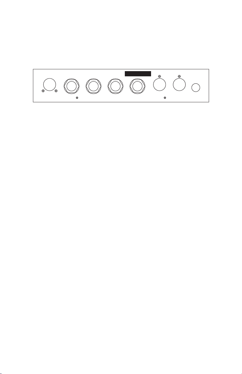
RJM Amp Gizmo User manual

Amp Gizmo
User’s Manual
RJM Music Technology, Inc.


Amp Gizmo
User’s Manual
Version 1.0
ugust 22, 2005A
RJM Music Technology, Inc.
1833 Diamond Street #103
San Marcos, CA 92078
(760) 752-1001
Web: www.rjmmusic.com

Copyright © 2005 RJM Music Technology, Inc. All Rights Reserved.
AMP GIZMO, Piezo Gizmo and the RJM logo are trademarks of RJM
Music Technology, Inc.

Introduction
Thank you for purchasing an AMP GIZMO. This product is designed to
connect your amplifier, effects devices or other electronic equipment to
other MIDI-enabled equipment. The AMP GIZMO can control any
device that uses short-to-ground switching. This means that virtually
any function that is controlled by a footswitch can be MIDI controlled
using the AMP GIZMO. It’s even possible to control more than one
device at a time, depending on the number of functions you need to
switch.
Devices that use ¼” mono or stereo jacks for switching purposes are
supported with no special cable required. Custom cables are available
to control equipment that uses non-standard connectors. Many types of
custom cables are available now and we will continue to develop new
cables to support other amplifiers and equipment.
1

Front Panel
12341234Wr i t e
Amp Gizmo
RJM M u si c Te ch n o l o g y , I n c.
Ch an n e l s Fu n c t i o n s
Channel buttons 1 through 4 – These buttons control the channel
functions of the connected device. The channel buttons can work in two
different modes:
Dependent Mode (default) – pressing one of these four
buttons will turn on the associated channel switch and turn off
the other three channel switches. Exactly one channel switch
will be on at all times.
Independent Mode – pressing one button will toggle its
switch state (if it was on, it will turn off and vice versa). The
other channel switches are unaffected. Each channel switch is
independent of the others.
Refer to the setup mode section of this manual for more information on
Independent and Dependent Modes.
Each channel button has a red LED next to it. When a channel switch is
on, its LED is lit.
Function buttons 1 through 4 – These buttons control the non-
channel functions of the connected device. On a typical amplifier, these
functions might be reverb, effects loop or boost. Pressing one of these
buttons will toggle the state of the associated function.
Each function button has a green LED next to it. When a function
switch is on, its LED is lit.
2

Write – When held down for 2 seconds, this button saves the current
switch state to non-volatile memory. This function is not active until a
Program Change message is received at the MIDI In jack. See the
section on MIDI Usage for more details.
3

Back Panel
RJM M u si c Te ch n o l o g y , I n c
.
www.rjmmusic.com
To A m p l i f i e r Ch an
1/2
Ch an
3/4
Fu n c t i o n
1/2
Fu n c t i o n
3/4
MIDI Thru MIDI In Po w e r
9-18V AC/ DC
Co p y r i g h t © 2 0 05 RJM Mu si c Tec h n o l o g y, I n c. M o d e l A G- 1 Se r i al No .
To Amplifier – Connect the custom amplifier interface cable here. Use
the cable end that has a yellow label reading “AMP GIZMO.” The other
end of the cable plugs into your amp’s footswitch jack. Before
connecting, make sure that you have the cable that’s made specifically
for your amp. Cables are available for a variety of makes and models of
amplifiers. Check our website for a list of currently available cables.
Chan 1/2 – This jack is for channel switches 1 and 2. You can plug a
mono or stereo (TRS) ¼” cable here. The Channel 1 switch is on the tip
conductor and the Channel 2 switch is on the ring conductor (when
using a TRS cable).
Chan 3/4 – This jack is for channel switches 3 and 4. You can plug a
mono or stereo (TRS) ¼” cable here. The Channel 3 switch is on the tip
conductor and the Channel 4 switch is on the ring conductor (when
using a TRS cable).
Function 1/2 – This jack is for function switches 1 and 2. You can plug
a mono or stereo (TRS) ¼” cable here. The Function 1 switch is on the
tip conductor and the Function 2 switch is on the ring conductor (when
using a TRS cable).
Function 3/4 – This jack is for function switches 3 and 4. You can plug
a mono or stereo (TRS) ¼” cable here. The Function 3 switch is on the
tip conductor and the Function 4 switch is on the ring conductor (when
using a TRS cable).
MIDI Thru – All of the MIDI commands that are received at the MIDI
In jack are sent out through this jack.
4

MIDI In – Jack for incoming MIDI commands. Connect your MIDI
foot controller here. The AMP GIZMO will phantom power a compatible
MIDI controller if you use a 7-pin MIDI cable. The AC adapter
provided with the AMP GIZMO can phantom power most MIDI
controllers provided that they can run on a 9V AC supply. However, if
your MIDI controller needs more than 800mA, an adapter with a higher
current capacity is recommended.
Power – This unit requires power supply in the range of 9 to 18 volts,
AC or DC. The plug should be a 5.5mm/2.1mm barrel connector,
similar to those used in most effects pedals. The AMP GIZMO requires
as much as 200mA for very short periods of time when switching
functions, but most of the time requires only a couple of milliamps.
5

MIDI Usage
The AMP GIZMO can receive MIDI messages from any MIDI controller.
You can store different switch settings for MIDI program numbers 1
through 120. Program numbers 121 through 128 are not supported and
will be ignored by the AMP GIZMO. When a Program Change message
is received on the correct channel, the AMP GIZMO will automatically
recall the saved settings for the given program number.
To set up for MIDI use, simply connect your MIDI controller to your
AMP GIZMO’s MIDI In jack. The AMP GIZMO is set for MIDI Channel 1
by default. Either make sure your MIDI controller is set up to transmit
commands on Channel 1, or use the AMP GIZMO’s setup mode to
change which MIDI channel the AMP GIZMO responds to. See the setup
mode chapter for more details.
To save a program setting, perform the following steps:
1. Using your MIDI controller, select a MIDI program number.
2. Using the AMP GIZMO buttons, set the desired state of each
channel and function.
3. Hold down the Write button on the AMP GIZMO until the
LEDs flash. This should take about 2 seconds.
That’s all it takes. You can repeat this for any or all of MIDI program
numbers 1 though 120.
If the lights don’t flash after a few seconds of holding down the Write
button, it means that your AMP GIZMO did not receive the MIDI
Program Change message. Check your MIDI cable connection, and
make sure that the MIDI controller and AMP GIZMO are set to the same
MIDI channel.
Now that your settings have been saved, you can recall your settings by
using your MIDI controller to send a Program Change message again.
The AMP GIZMO will call up your saved settings and set the channel
and function switches whenever it receives a MIDI Program Change
message.
6

Continuous Controllers
In addition to supporting MIDI Program Change messages, the AMP
GIZMO supports MIDI Continuous Controller messages. The following
Continuous Controllers are supported:
Continuous Controller Value Function
CC88 0
1 127
Channel 1 off *
Channel 1 on
CC89 0
1 127
Channel 2 off *
Channel 2 on
CC90 0
1 127
Channel 3 off *
Channel 3 on
CC91 0
1 127
Channel 4 off *
Channel 4 on
CC92 0
1 127
Function 1 off
Function 1 on
CC93 0
1 127
Function 2 off
Function 2 on
CC94 0
1 127
Function 3 off
Function 3 on
CC95 0
1 127
Function 4 off
Function 4 on
*Channel Independent Mode only (any value turns channel on in
Dependent Mode).
Please note that settings such as Momentary Mode and
Dependent/Independent Mode are in effect when processing
Continuous Controller messages.
7

Controlling Multiple Devices
Each of the switching jacks on the AMP GIZMO is electrically isolated
from the others. Because of this, it’s possible to safely control multiple
devices. For example, you could control an amplifier that has three
channels and two switchable functions, plus an effects device that has
two switchable functions – using just one AMP GIZMO. This could be
done in several ways:
•Connect the amplifier to the “To Amplifier” jack using an
appropriate custom cable. Connect the effects device to the
“Function 3/4” jack using a ¼” cable.
•Connect the amplifier to the “Chan 1/2”, “Chan 3/4” and
“Function 1/2” jacks using ¼” cables. Connect the effects
device to the “Function 3/4” jack using a ¼” cable.
These are only two possibilities – there are many more configurations
that can be used. As long as you connect only one device to each jack,
you have a safe configuration.
Don’t use a Y cable to control two different pieces of equipment from a
single jack! That could lead to ground loops or, even worse, damage
your equipment.
An important thing to note is that, although they are electrically
isolated, the amplifier jack and ¼” jacks are not independently
switched. For example, if you press the Channel 1 button , the Channel
1 pin of the “To Amplifier” jack and the Channel 1 half of the “Chan
1/2” jack will both be turned on (i.e. shorted to connector ground) at the
same time. The same is true for all of the eight switchable functions –
each one simultaneously controls a pin on the “To Amplifier” jack and
the corresponding conductor on one of the four ¼” jacks.
You can take advantage of this arrangement if you have two amplifiers
that need to be switched at the same time. If you use the appropriate
cables, you can make the two amps switch channels and functions
simultaneously – one connected using a custom cable and the other
using ¼” cables.
8

Setup Mode
Setup mode allows you to change how the AMP GIZMO’s MIDI and
switching functions work. To enter setup mode, make sure the AMP
GIZMO is turned off. Next, hold down the Channel 4 button while
applying power to the AMP GIZMO. Keep holding the button until the
lights on the unit flash three times. You’re now in setup mode.
Setting MIDI Channel
In setup mode, the channel buttons allow you to select which MIDI
channel the AMP GIZMO responds to. Use the channel buttons to turn
the channel LEDs on or off to get the desired pattern shown below:
MIDI
Channel
Channel 1
LED
Channel 2
LED
Channel 3
LED
Channel 4
LED
1 OFF OFF OFF OFF
2 ON OFF OFF OFF
3 OFF ON OFF OFF
4 ON ON OFF OFF
5 OFF OFF ON OFF
6 ON OFF ON OFF
7 OFF ON ON OFF
8 ON ON ON OFF
9 OFF OFF OFF ON
10 ON OFF OFF ON
11 OFF ON OFF ON
12 ON ON OFF ON
13 OFF OFF ON ON
14 ON OFF ON ON
15 OFF ON ON ON
16 ON ON ON ON
9

Setting Switch Modes
In setup mode, the function switches allow you to set different switch
modes. Unless changed manually, all of these modes are off by default.
Channel Momentary Mode
If the Function 1 LED is on, the channel switches operate in
Momentary Mode. Any time a channel switch changes state,
the channel’s relay is turned on for 100 milliseconds, then
turned off.
If the Function 1 LED is off, the channel switches operate
normally. When a channel LED is lit, its relay is on. When a
channel LED is not lit, its relay is off.
Function Momentary Mode
If the Function 2 LED is on, the function switches operate in
Momentary Mode. Any time a function switch changes state,
the function’s relay is turned on for 100 milliseconds, then
turned off.
If the Function 2 LED is off, the function switches operate
normally. When a function LED is lit, its relay is on. When a
function LED is not lit, its relay is off.
Channel Independent Mode
If the Function 3 LED is on, the channel switches operate in
Channel Independent Mode. Each channel switch can be
turned on or off independently of the others.
If the Function 3 LED is off, the channel switches operate in
Channel Dependent Mode. Selecting one channel switch will
turn that switch on and turn the other channel switches off.
Only one channel switch is allowed to be on at a time.
10

Exiting Setup Mode
To exit setup mode, unplug the AMP GIZMO. Wait a couple of seconds,
then apply power again. Don’t hold any buttons down while powering
up. The AMP GIZMO is now operating normally. The changes you made
in setup mode are saved automatically.
11

Invert Mode
On some amplifiers, you may find that a function is on when the AMP
GIZMO says it’s off, and the function is off when the AMP GIZMO says
it’s on. This is an inverted function. To make the function switch
correctly, first make sure the AMP GIZMO is unplugged. Next, hold
down the Function 4 button while applying power to the AMP GIZMO.
Keep holding the button until the lights on the unit flash five times.
You’re now in invert mode.
In invert mode, use the front panel buttons to light the LED of any
channel or function that is inverted. Make sure that all other channel
and function LEDs are not lit.
Once you’ve done this, unplug the AMP GIZMO. Wait a couple of
seconds, then apply power again. Don’t hold any buttons down while
powering up. The AMP GIZMO is now operating normally, and the
inverted channels and functions will operate correctly now.
12

Warranty
RJM Music Technology, Inc. warrants this product against any defects
that are due to faulty material or workmanship for a period of one year
from the date of original retail purchase. This warranty does not cover
damage to the product resulting from accident or misuse.
This warranty is transferable provided the current owner has the
original purchase receipt and can provide a copy of it when submitting
the warranty claim.
Should you experience any difficulty with this RJM Music product,
please contact us as described below. If it is determined that the product
has become defective within the warranty period and must be returned
to the factory, RJM Music Technology will issue a Returned
Merchandise Authorization (RMA) number and shipping and
packaging instructions.
RJM Music Technology will repair or replace the product free of
charge, provided it is returned freight prepaid to RJM Music
Technology with a valid receipt and RMA number. Return shipping
will be paid by RJM Music Technology within the U.S. only.
This warranty shall not apply to any goods that have been repaired or
altered by anyone other than the manufacturer. There are no warranties
which extend beyond the terms described herein.
RJM Music Technology, Inc.
1833 Diamond Street #103
San Marcos, CA 92078
Phone: (760) 752-1001
E-Mail: support@rjmmusic.com
13

Other manuals for Amp Gizmo
1
Table of contents
Other RJM Music Pedal manuals
Popular Music Pedal manuals by other brands

Harley Benton
Harley Benton BCH-1 user manual

Electro-Harmonix
Electro-Harmonix XO Bass Metaphors manual

Harley Benton
Harley Benton Double Jammer quick start guide

Rocktron
Rocktron TRUE BYPASS Tru-Loop instruction manual

Vox
Vox Tonelab ST Service manual

Electro-Harmonix
Electro-Harmonix Silencer quick start guide