RJX Hobby X-Tron 500V2 FBL User manual

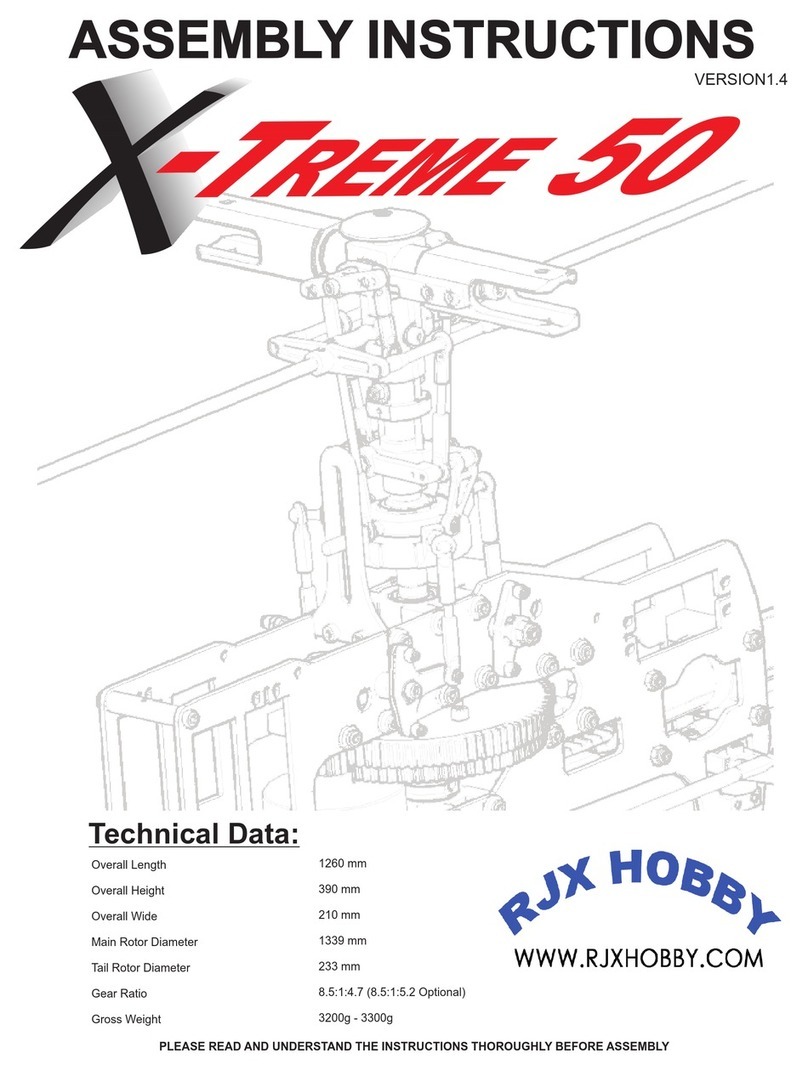
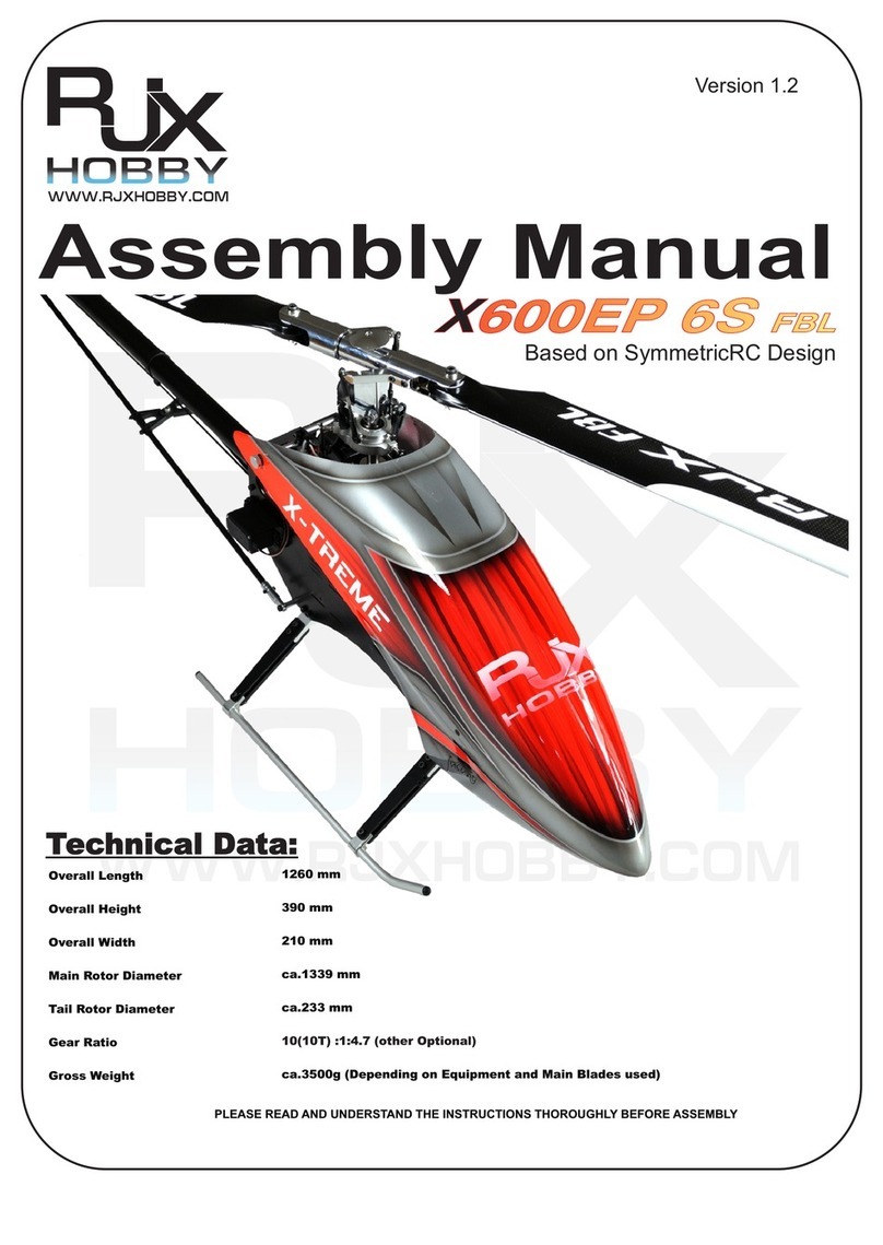
Overall Length
Overall Height
Overall Width
Main Rotor Diameter
Tail Rotor Diameter
Gear Ratio
Gross Weight
1185 mm
267 mm
180 mm
ca.980 mm
ca.214 mm
11.06(16T) / 12.64(14T):1:4.69
ca.1850g (Depending on Equipment and Main Blades used)
PLEASE READ AND UNDERSTAND THE INSTRUCTIONS THOROUGHLY BEFORE ASSEMBLY
Technical Data:
Assembly Manual
X
-Tron 500V2 FBL
-Tron 500V2 FBL
Version 1.1

INTRODUCTION
Please read this manual carefully. It is essential for the correct assembly of the
For the correct assembly and safe flying, this manual uses this symbol where special attention is required in the assembly of
your model. It is very important that you follow the instructions at these points in the manual. Failure to do so can lead to the loss of
control of the model without warning and the possibility of serious accidents or injury.
NOTE Failing to carry out the instructions at this point in the assembly manual will
probably result in an Electronics or mechanical failure occurring without warning..
IMPORTANT Means that special care is required at this point for correct assembly.
Disclaimer:
While every effort has been made to supply the correct information in this manual, The Manufacturer and Distributor
cannot guarantee that the purchaser will interpret or follow these instructions as intended and therefore the
Manufacture and Distributor assumes no liability for damage or claims that may occur from the use/misuse of this
product.
Do not be fooled it is NOT easy to fly R/C Helicopters
It may look easy when watching an experienced pilot flying his model, but perseverance and hours of practice will be needed before
you will be able to fly and opperate the model safely. RJX HOBBY suggests you join a club or seek help from an experienced pilot to
assist you in your first test flights and then as with all things the more you practice the better you will become. We encourage you to
practice often and enjoy the experience of RC rotary flight!
WARNING
LiPo batteries need special care. Improper handeling or charging can cause fire and damage to your Helicopter and yourself. Contact
your dealer or supplier for more information.
1. Check your charger settings before charging your LiPo battery to insure they are correct for the specifications of the battery.
2. We recommend storing and charging LiPo batteries in a lipo sack or porcelain container." If kept in a metal container or ammo
case, explosion could occur if these cases are sealed and gases are not allowed to vent. We recommand to use the original
LipoSack from the USA since it has been actually designed and tested by a firefighter to contain the jet flames discharged from
a failing lipo battery.
3. Please keep LiPo Batteries away from sources of heat..
4. Never store LiPo Batteries fully charged. Check the information on your batteries.
5. NEVER SHORT OUT LiPo Battery wires.
6. Before conecting your LiPo battery to the Helicopter,make sure your transmitter is turned ON and all sticks and switches are
set properly.
X
-Tron 500 FBL
-Tron 500 FBL
I1

TABLE OF CONTENTS
1. Introducion
2. Table of contents
3. Additional Items Required
4. Tools Required
5. Assembly
6. Servo Installation
7. Servo Adjustment
8. Final Servo and Radio Setup
9. Please read before flight
10. Spare Parts List
I1
I2
I3
I4
A1 - A16
S1-S4
S5-S9
R1-R5
Pf1
SP1 - SP5
This manual contains the detailed instructions to build and set up the X-Tron 500FBL. Please follow it to ensure that you
achieve the best performance and mechanical integrity from your finished kit. For those of you who already have
experience with model helicopters, we still suggest that you assemble and adjust your model according to these
instructions for the best results. Please keep your copy of this manual in a safe place and refer to it when replacing
spare parts or upgrading.
Remove oil and grease then apply threadlock. (This applies throughout the manual)
Remove oil and grease. (This applies throughout the manual)
Please refer to the list at the end of this instruction manual when you need spare parts.
Regardless how tight the nuts, bolts and screws are tightened, they will still slowly come loose over a period of time
due to vibration from the helicopter. Should this happen the helicopter will become out of control or severely damaged
causing a very potential dangerouse situation.
We strongly recommend that you apply threadlock to any nuts, bolts or screws that are indicated by these signs.
There are two types of threadlock, blue (medium) and red (hard) . Use blue threadlock on screws
that have to be removed regularly and red threadlock for screws that should be fixed permanently. Clean them
with Alcohol (or similar) before you apply the threadlock.
TO PREVENT LOOSE SCREWS AND BOLTS
HOW TO USE THIS INSTRUCTION MANUAL
Use CA (Superglue or similar) at this point
CA
I2

ADDITIONAL ITEMS REQUIRED TO COMPLETE THE
CCPM compatible PCM or 2,4Ghz Radio System
with 3 or 4 Mid Servos (Tail can be Standard or Mid) 3 Axis Virtual Flybar Sytem Three large and one small
servo arm are required
3226-1600kv(6S) Brushless Motor
(if not delivered) Lipo Pack from 4S-8S (Depending on setup) 80A ESC (if not delivered)
430mm CF Main Blades
(if not delivered)
X
-Tron 500 FBL
-Tron 500 FBL
20mm
3X
1X
13mm
I1

TOOLS REQUIRED (NOT INCLUDED)
Allen Drivers 1,5mm - 2mm - 3mm - 4mm Phillips Drivers Large,Middle, Small Nut Drivers 4,5mm - 5,5mm - 7mm
Cutter Universal Pliers Scissors
Sandpaper Ball Link Plier Metric Ruler Pitch Gauge
Cyanoacrylate (CA/Superglue) Epoxy 30 Minutes Grease
Ball Link Driver
Ball Link Tool
I1

STEP 1 MAIN DRIVE
Bag Content:
1x 177T Main Gear
1x 155T Taildrive Gear
1x Auto Shaft
1x Autorotation Unit
1x Tail Drive Hub
8x M3x6 Counter Sunk Hex Screws
M3X6(4)
155T
M3X6(4)
AUTO SHAFT
177T
AUTOROTATION UNIT
TAIL DRIVE HUB
A1

STEP 2 LANDING GEAR
Bag Contend:
2x Skid Brace
8x Landing Skid Struts
4x Skidholder
2x Skids
1x Canopy Mount
8x M2,5x10 Socket Head Screws
2x M2,5x8 Socket Head Screws
4x M3x12 Socket Head Screws
4x M3 Lock Nut
8x M2,5 Lock nut
M2,5x8(2) M2,5x10(8)
M2,5 Lock Nut(8)
M3 Lock Nut(4)
Landing Skid(2)
Skid Holder(4)
M3x12(4)
Struts(8)
Lower Canopy
Standoff
Canopy Support
Skid Brace(2)
A2

STEP 3-1 MAIN FRAME
Bag Contend:
2x Main Frame
2x Battery Tray Guides
10x M2x5 Socket Head Screws
M2x5(10)
Main Frame
Battery Tray Guide
CA
Add CA to the M2x5 Screws to
improve their hold in the Guides
A3

STEP 3-2 MAIN FRAME
Bag Contend:
1x Upper Bearing Block
1x Lower Bearing Block
2x Boom Holder
12x M2,5x8 Socket Head Bolt
1x Frame Stiffener
Check for the correct
mounting of the Bearing
Blocks.
M2,5x8(12)
Boom Holder
Lower Bearing Block
Upper Bearing Block
Frame Stiffener
A4

STEP 3-3 MAIN FRAME
Bag Contend:
2x 50mm Crossmember
17x M2,5x8 Socked Head Bolt
1x ESC Mount
2x Canopy Breakoff
1x Electronics Mount
2x Canopy Mount
1x Frame Stiffer 2
M2,5x8(13)
M2,5x8(4)
50mm Crossmember
ESC Mount
Electronics Mount
50mm Crossmember
Canopy Mount(2)
Secure the ESC Mount, Electronics Mount and the Frame Stiffener with CA.
Check position for hole
A5
NO SCREWS (will be
fixed in STEP 6-2)
Frame Stiffer 2

STEP 3-4 MAIN FRAME
Bag Contend:
1x Swash Guide
1x 33T Tail Gear Pinion
1x 16T S3M Pulley
1x Lower Tail Gear Mount
1x M3x6 Socket Head Bolt
1x M3x8 Socket Head Bolt
1x 3x8x1 Washer
3x M2,5x8 Socket Head Bolt
Swash Guide
M2,5x8
M3x6
16T S3M
Pulley
M2,5x8
Lower Tail Gear Mount
(Flange downwards)
33T Tail Pinion
M3x8
3x8x1 Washer
A6

STEP 3-5 MAIN FRAME
Bag Contend:
1x Main Shaft
1x Main Shaft Collar
1x M2,5x10 Socket Head Bolt
2x M3x8 Socket Head Bolt
Main Shaft
Hole closer to end of the
shaft goes down
Main Shaft Collar M2,5x10
M3x8
M3x8
After affixing the 2 M3x8 Socket Head Bolts, pull up on the main Shaft
and tighten the M2,5x12 Socket Head Bolt.
Do not overtighten the M3x8 main shaft bolts so as not to distort the gears.
Bolts should be snug.
A7

STEP 3-6 MAIN FRAME
Bag Contend:
4x M2,5x8 Socket Head Bolt
4x 2,6x7x1 Washer
2,6x7x1 Washer
M2,5x8
M2,5x8
2,6x7x1 Washer
DO NOT use thread lock on the Landing Gear's M2.5x8 bolts. This allows the
landing gear to slip out of the frame in the event of a crash.
A8

STEP 4-1 Rotor Head
Bag Contend:
1x Center Hub
1x Spindle
2x Blade Holder
2x Pitcharm
2x 90º Dampener
2x Collar
2x Thrust Bearing
2x Thrust Washer
2x Swashlock Arm
4x M2,5x8 Socket Head Bolt
2x M3x10 Socket Head Bolt
1x M2x8 Socket Head Bolt
2x M3x20 Socket Head Bolt
2x 3x5x1 Washer
Blade Holder
Center Hub
Spindle
90º Dampener
Collar
Thrust Washer
Thrust Bearing
(Bigger ID inside
Smaller ID outside)
3x8x1 Washer
M3x10
M2x8
Stopper
M2,5x8
Pitcharm
4mm Joint Ball
3x5x1 Washer
Swashlock Arm
M3x20
Apply grease to the Thrust Bearings
and Dampeners!
A9

STEP 4-2 Swashplate
Bag Contend:
1x Swashplate
3x 9mm Joint Ball
4x 4mm Joint Ball
4mm Joint Ball
9mm Joint Ball
A10

STEP 4-3 Installation
Bag Contend:
1x M3x16 Socked Head Bolt
1x Delrin Guide
1x M2,5x17 Socked Head Bolt
1x M2,5 Lock Nut
M3x16
Delrin Guide
M2,5 Lock Nut
M2,5x17
Tighten the M3x16 Socket Head Bolt to allow the Delrin guide to move smoothly
in the Swash Guide.
Clip the two Swashlock Links onto the corresponding balls.
There are 3 different adjustments for
center hub height. Use the Standard
position in the middle hole of the
center hub.
A11

STEP 5-1 Tail Section
Bag Contend:
1x Tailcase
1x 16T S3M Pulley
1x 14mm Pin
1x Tail Shaft
1x M3x4 Set Screw
1x Tail Control Arm Support
1x Tail Control Arm
2x M2,5x6 Socket Head Bolt
1x M2x5 Socket Head Bolt
1x M3x25 Socket Head Bolt
2x 3x5x2 Washer
1x Joint Ball
16T S3M Pulley
14mm Pin
Tail Shaft
Tail Case
M3x4
To remove the tail shaft, heat the
14mm pin with the tip of a
soldering iron and press out with
a small screwdriver or use a draft
pin and arbor press.
M2,5x6
3x5x2 Washer
Tail Control Arm
3x5x2 Washer
M3x25
Tail Control Arm Support
M2x5
Joint Ball
A12

STEP 5-2 Tail Section
Bag Contend:
2x Tail Blade Holder
1x Tail Center Hub
1x Copper Sleeve
1x Slide Ring
1x Pitch Fork
3x Joint Ball
2x M2x8 Socket Head Bolt
1x M2x5 Socket Head Bolt
2x Thrust Bearings
2x Thrust Washer
2x M3x10 Socket Head Bolt
2x 3x8x1 Washer
Tail Hub
M2x8
Joint Ball
Tail Blade Holder
Thrust Washer
Larger OD Thrust Ring
Thrust Ball Ring
Small ID Thrust Ring
M3x10
3x8x1 Washer
Use grease on the Thrust Bearing!
Copper Sleeve
Slide Ring
Joint Ball
M2x5
Pitch Fork
A13

STEP 5-3 Tail Section
Bag Contend:
2x 70mm Tail Blades
2x M3x20 Socket Head Bolt
2x M3 Lock Nut
2x M4x4 Set Screw
4x 3x10x1,5 Washer
M4x4
70mm CF Tail Blade
M3x20 M3 Lock Nut
3x10x1,5 Washer
A14

STEP 5-4 Tail Section
Bag Contend:
1x Tail Fin Set
1x S3M 1119 Belt
1x Tailboom
2x M3x6 Socket Head Bolt
2x M3x8 Socket Head Bolt
CA
Tail Boom
S3M Belt
M3x6
M3x8
A15
Table of contents
Other RJX Hobby Toy manuals
Popular Toy manuals by other brands

Chicco
Chicco HELICO MUSICAL manual

Hasbro
Hasbro Fur Real Friends Cuddles My Giggly Monkey manual
Little Tikes
Little Tikes Slammin' Racers Runaway Railroad quick guide
Faller
Faller 191794 manual
ROBBE
ROBBE Air Beaver Assembly and operating instructions

Finwing Technology
Finwing Technology Traveler 1400MM user manual
Rapido Trains
Rapido Trains F40PH-2D manual
Freewing
Freewing Spacewalker instruction manual
Eduard
Eduard Leopard 2A6 Assembly instructions
REVELL
REVELL Bristol F.2B Fighter Assembly instructions

Parkside
Parkside PP 1500 A1 Operation and safety notes
Pilot-1
Pilot-1 Aeronca Champ Assembly instructions & owner's manual
