RJX Hobby x800 ep User manual

Technical Data:
Overall Length
Overall Height
Overall Wide
Main Rotor Diameter
Tail Rotor Diameter
Gear Ratio
Gross Weight
ca.2000 mm
430 mm
210 mm
ca.1800 mm
ca.301 mm
5200g - 5600g (Depending on Equipment and Main Blades used)
10:1:4.7 (others Optional)
PLEASE READ AND UNDERSTAND THE INSTRUCTIONS THOROUGHLY BEFORE ASSEMBLY
Version 1.0
800

INTRODUCTION
Please read this manual carefully. It is essential for the correct assembly of the
For the correct assembly and safe flying, this manual uses this symbol where special attention is required in the assembly of
your model. It is very important that you follow the instructions at these points in the manual. Failure to do so can lead to the loss of
control of the model without warning and the possibility of serious accidents or injury.
NOTE Failing to carry out the instructions at this point in the assembly manual will
probably result in an electronic or mechanical failure occurring without warning..
IMPORTANT Means that special care is required at this point for correct assembly.
Disclaimer:
Whilst every effort has been made to supply the correct information in this manual, The Manufacturer and Distributor
cannot guarantee that the purchaser will interpret or follow these instructions as intended and therefore the
Manufacture and Distributor assumes no liability for damage or claims that may occur from the use/misuse of this
product.
Do not be fooled it is NOT easy to fly R/C Helicopters
It may look easy when watching an experienced pilot flying his model, but perseverance and hours of practice will needed before you
will be able to fly and opperate the model safely. RJX HOBBY suggests you join a club or seek help from an experienced pilot to help
you in your first hops off the ground and then as with all things the more you practice the better you will become. Who knows you could
be the next world champion.
WARNING
The fuel used in model helicopter engines is highly inflammable and poisonous to human beings. For your own safety and that of
others, you should exercise care when handling and storing it. Always read the label on the container and please note the cautions
below.
1. Model helicopter fuel is highly inflammable. Do not smoke or light fires near your fuel.
2. We recommend that you keep your fuel in metal cans or plastic bottles and to store it where there is no risk of fire.
3. Please keep fuel away from the starter battery. It only needs one spark and…..!!!
4. Wipe up spilt fuel immediately. Do not take any chances.
5. Do not leave fuel in the sun or in you car on a hot day.
6. Before refuelling, shut off the engine and wait until it cools down.
7. Always drain the fuel tank of you helicopter at the end of a flying session. It is good practice.
I1
800

I2
TABLE OF CONTENTS
1. Introducion
2. Table of contents
3. Additional Items Required
4. Tools Required
5. Assembly
6. Servo Installation
7. Servo Adjustment
8. Rotor Head Setup
9. Final Servo and Radio Setup
10. Please read before flight
11. Spare Parts List
I1
I2
I3
I4
A1 - A29
S1-S4
S5-S6
A17
R1-R5
Pf1
SP1 - SP7
This manual contains the detailed instructions to build and set up the . Please follow it to ensure that you
achieve the best performance and mechanical integrity from your finished kit. For those of you who already have
experience of model helicopters, we still suggest that you assemble and adjust your model according to these
instructions for the best results. Please keep your copy of this manual in a safe place and refer to it when replacing
spare parts or upgrading.
Remove oil and grease then apply threadlock. (This applies throughout the manual)
Remove oil and grease. (This applies throughout the manual)
Please refer to the list at the end of this instruction manual when you need spare parts.
Regardless how tight the nuts, bolts and screws are tightened, they will still slowly come loose over a period of time
due to vibration from the helicopter. Should this happen the helicopter will become out of control or severely damaged
causing a very potential dangerouse situation.
We strongly recommend that you apply threadlock to any nuts, bolts or screws that are indicated by these signs.
There are two types of threadlock, blue (soft) and red (hard) . Use blue threadlock on screws
that have to be removed regularly and red threadlock for screws that should be fixed permanently. Clean them
with Alcohol (or similar) before you apply the threadlock.
TO PREVENT LOOSE SCREWS AND BOLTS
HOW TO USE THIS INSTRUCTION MANUAL
Use CA (Superglue or similar) at this point
CA
800
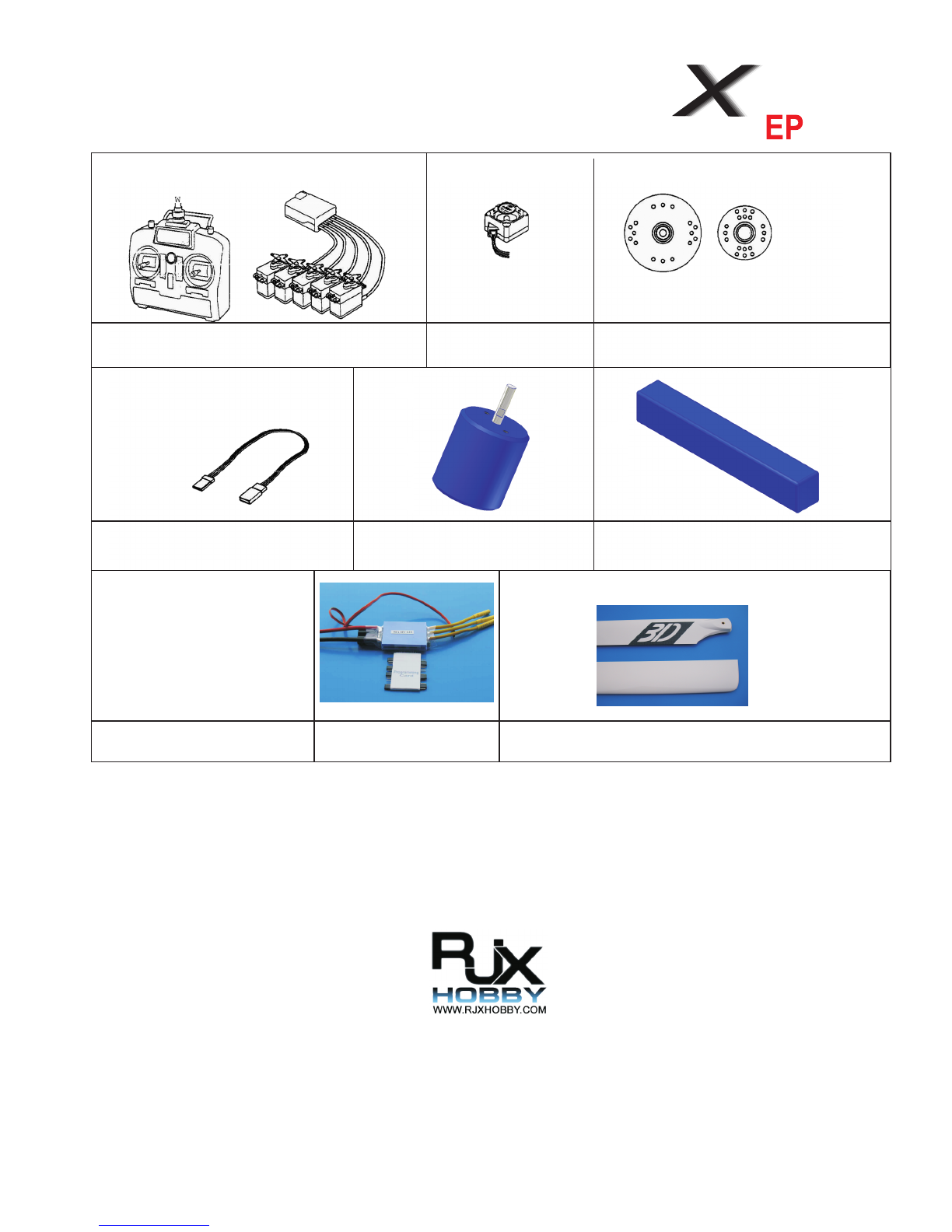
ADDITIONAL ITEMS REQUIRED TO COMPLETE THE
I3
Choose a CCPM compatible PCM Radio System for
Helicopters with a minimum of 6 channels.
Gyro system with
Heading Hold Three large and two small disks or
arms are required
1x Servo extension 100 mm
(depending on Servos) Brushless Motor (Outrunner)
300KV-450KV(10S-12S) 10-12S Li-Po Batterie Pack
Li-po/Ion Charger 120A-180A Brushless Motor ESC
for 10S-12S 800mm - 820mm Main Blades (for kits without Blades)
800
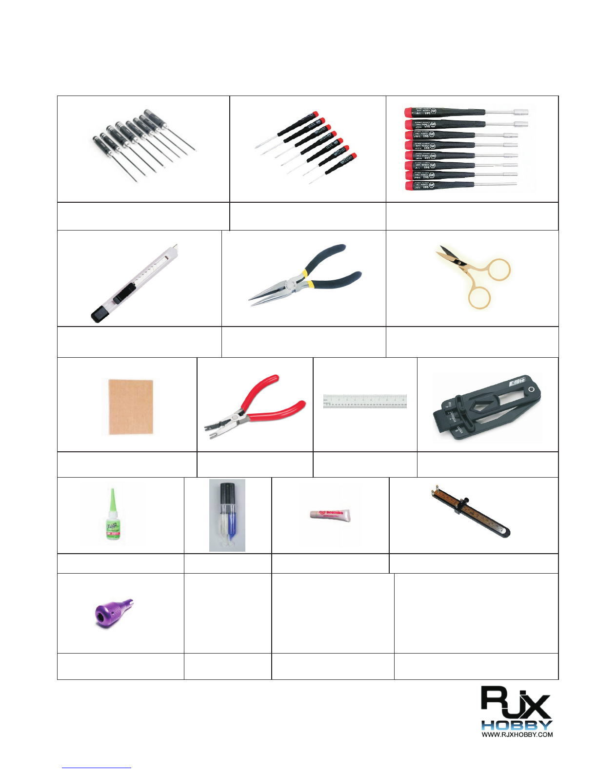
TOOLS REQUIRED (NOT INCLUDED)
I4
Allen Drivers 1,5mm - 2mm - 3mm - 4mm Phillips Drivers Large,Middle, Small Nut Drivers 4,5mm - 5,5mm - 7mm
Cutter Universal Pliers Scissors
Sandpaper Ball Link Plier Metric Ruler Pitch Gauge
Cyanoacrylate (CA/Superglue) Epoxy 30 Minutes Grease
Ball Link Driver
Ball Link Tool

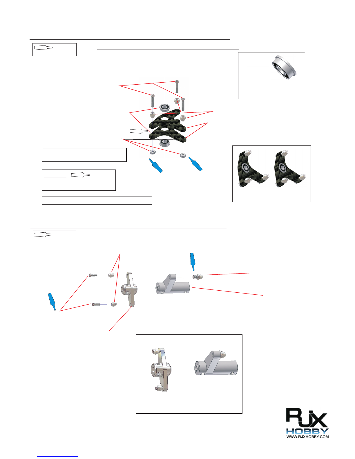
A1
STEP 1-1 Landing Skid Support Assembly
View of the complete Assembly.
.
USE THREADLOCK
M3x12
Landing Skid Mount A
Landing Skid Mount B
NOTE:Assemble 2 units.
Bottom Plate Mounting Block
LANDING SKID MOUNTS inside the bag of the MAIN FRAME
STEP 1-2TT Tail Drive Pinion Gear Assembly (TT Version)
Tail Drive Pinion
M3 Washer
M3x6 Socket Head Bolt
M3x4 Setscrew
12mm Pin
Output Shaft
19T Delrin Bevel Gear
19T Delrin Bevel Gear
M3x4 Setscrew
5x7x1 Washer
5x7x1 Washer
(if needed)
TT Gear Box
View of the complete Assembly.
Check that the gearmesh is correctly
(if necesary add a 0.2mm Nylon Washer) and
the assembly rotated freely but without play.
USE THREADLOCK IMPORTANT: Start assembly with the OUTPUT SHAFT.
IMPORTANT:
Add 0,2mm Nylon washer to
reach a PLAYLESS Gear mesh.
Check that the two gears are
perfectly aligned (shown in the
picture on the right).Stay on the
tight side of the gear mesh.
A ecssesive play can strip the
Delrin gear.
Lub the Bevel Gears regulary.
This step is preassembled.PLEASE CHECK AND ADD THREAD LOCK
Aligned

A2
STEP 1-3 Drive Gear Assembly
M3x8 Socket Head Bolt
93T Helical Main Gear
M3x6 Counter Socket Head Bolt
80T Tail Drive Gear
Tail Drive Gear Housing
Autorotation Shaft
Autorotation Spacer
IMPORTANT:
Stepped side facing downward
and entering completly inside
the bearing.
View of complete Assembly
CAUTION:
Clean off any dust on drive gears.
Add grease to the one way bearing,
to ensure smooth opperation.
Don´t fix the four M3x6 bolts before
having all four in place.
USE THREADLOCK
Autorotacion Unit
OPTIONAL:
93T Helical Main Gear
STEP 1-4 Canopy Stands
32mm Crossmember
M3x8 Socket Head Bolt
Breakoff
View of the completed Assembly
NOTE: Assemble 4 sets
BREAKOFF are inside the bag of the MAIN FRAME
USE THREADLOCK
A3
STEP 1-5 Swash Control Lever Assembly
M2x8 Socket Head Bolt
F3x6x2.5 Bearing with Flange
M2 Nut
Jointball
Control Lever
CA
View of the completed Assembly
CAUTION:
the two Control Lever parts.
Add a small amount of CA between
CA
CAUTION:
Control the correct fit of
the Flanged Bearings.
Flange facing upward
Flange facing downward
NOTE: Assembly 2 sets of this lever
USE THREADLOCK
CONTROL LEVER inside the bag of the MAIN FRAME
Add a 0.2mm Shim between the bearings if necesary
STEP 1-6 Rear Swash Control Assembly
USE THREADLOCK
M2x6 Socket Head Bolt
Joinball
4mm Ball Arm
Nick Arm
Rear Swash Lever
View of the completed Assembly

A4
STEP 1-7 Front Tail Arm Assembly
USE THREADLOCK
M2x10 Socket Head Bolt
M3x20 Socket Head Bolt
Joinball
Control Lever
Washer 3x5x1
Leverblock
View of the completed Assembly
CAUTION:
Do NOT over tighten the M3x20 bolts
to avoid breaking the bearings.
STEP 1-8 Battery Tray Assembly
USE THREADLOCK
M3x8 Countersunk Head Bolt
Battery Tray
View of the completed Assembly from both side
Special Crossmember
BATTERY TRAY inside the bag of the MAIN FRAME

A6
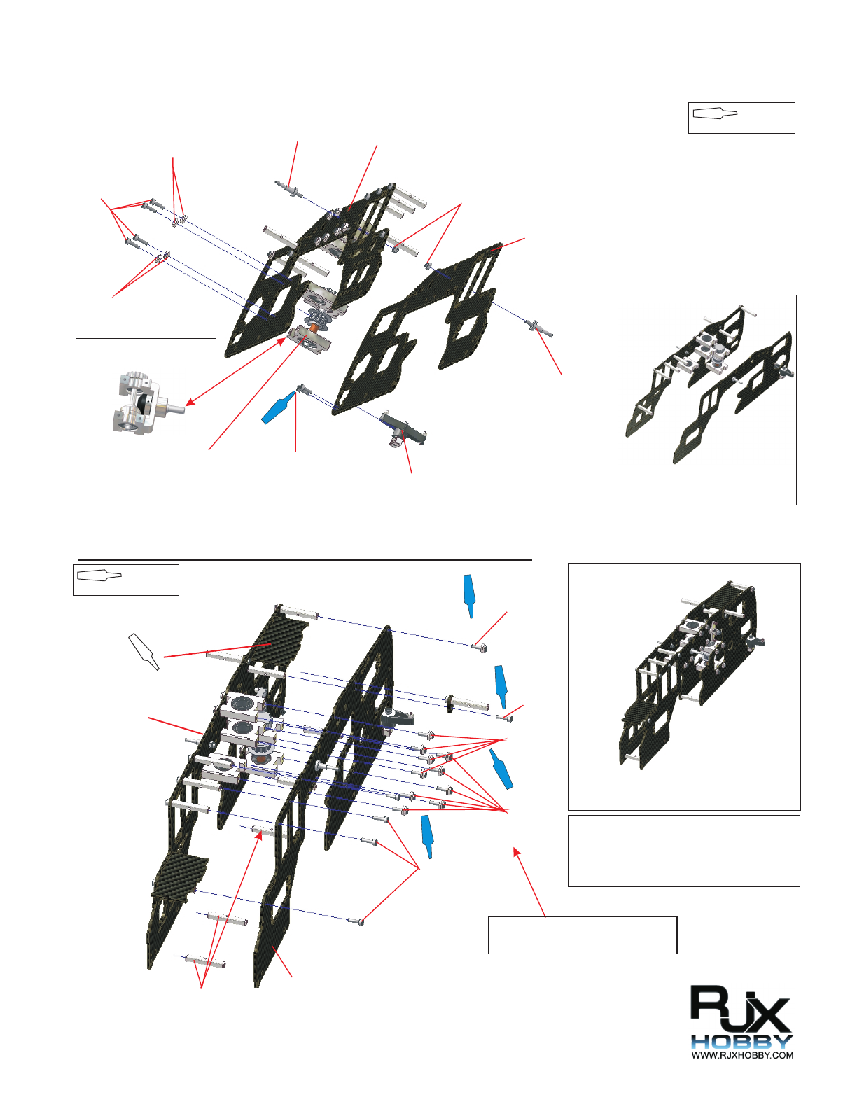
STEP 2-1 Lower Main Frame Assembly
USE THREADLOCK
Assambled in Step 1-1
M3x8
M3x10
M3x10
M3x8
M3x8
M3x8
60mm Crossmenber
Lower Frame
Lower Frame
Bottom Plate
View of the completed Assembly
CAUTION:
The upper main frame sides are NOT the same.
Look at the X50-EP writing cutout on the frame
sides to ensure that you have the correct sides.
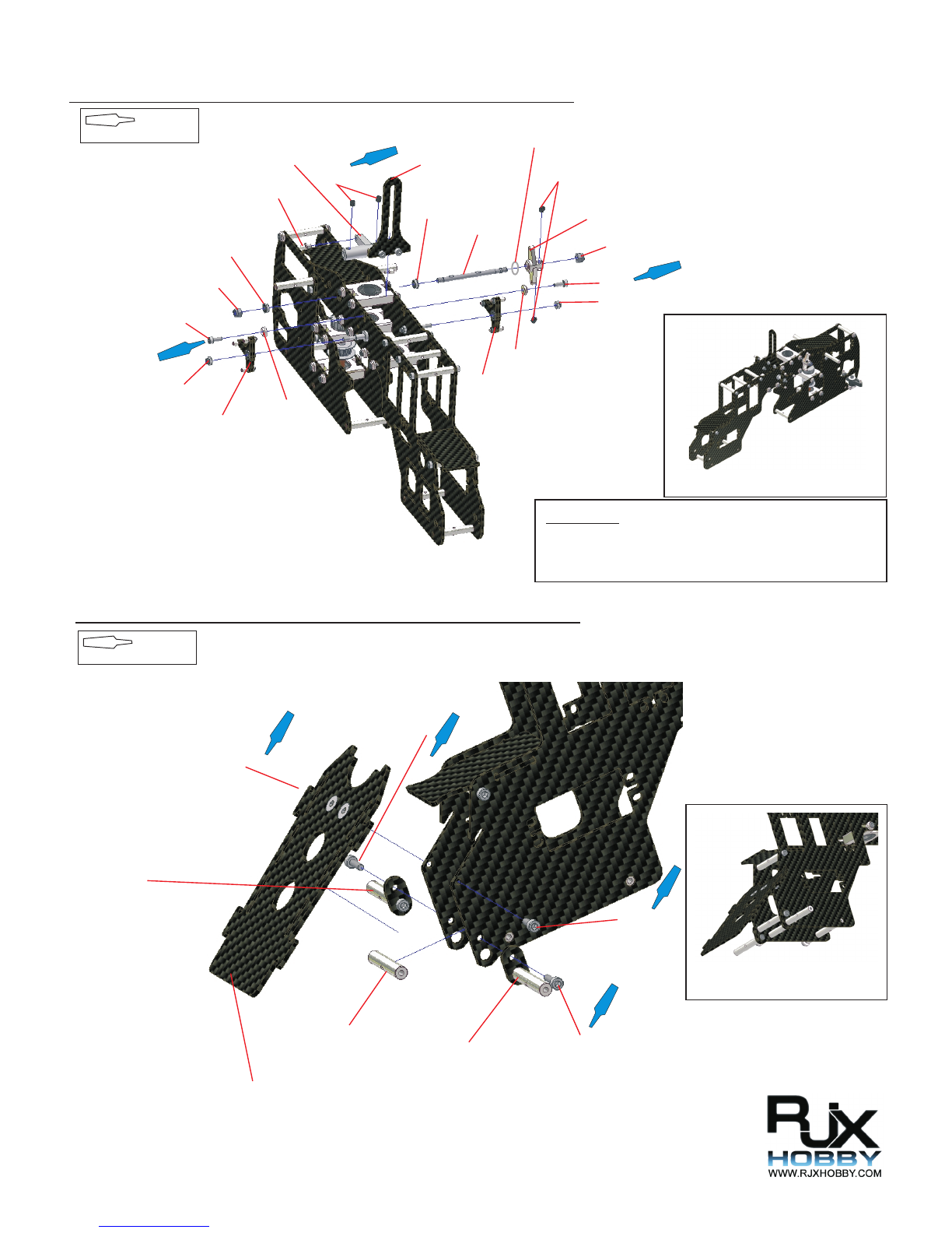
STEP 2-2 Upper Main Frame Assembly
USE THREADLOCK
View of the completed Assembly
BB Block
(Flange Down)
BB Block Pinion
(Flange Down)
BB Block
(Flange Up)
32mm Crossmember
32mm Crossmember
M3x10
Finish Cap
Right Upper Frame
Assembled in Step 1-4
M3x10
Flange
M3x10
(NO Threadlock
BB Block Pinion)
A7
STEP 2-3 Upper Main Frame Assembly
USE THREADLOCK
STEP 2-4 Upper Main Frame Assembly
USE THREADLOCK
View of the completed Assembly
View of the completed Assembly
M3x10
Finish Cap
Finish Cap
Standoff
Standoff
M3 Lock Nut
Assembled in Step1-2B
Assembled in Step2-2
Left Upper Frame
Gyro Mount
Assembled in Step 2-3
M3x10
M3x10
Finish Cap
Canopy Mount
Stepped Crossmember(5pcs.)
M3x8 (2)
Assembled in Step1-1
Note:
To ensure a perfect fit of the Gyro Mounts
use CA to fix them.
CA
Assembled
in Step 2-3
TT VERSION available only
Use the Assembly from
STEP1-2TT
M3x10
Do not use threadlock here to be able
attaching the belt in a later Step
M3x10
Finish Cap
M3x10
A8
View of the completed Assembly
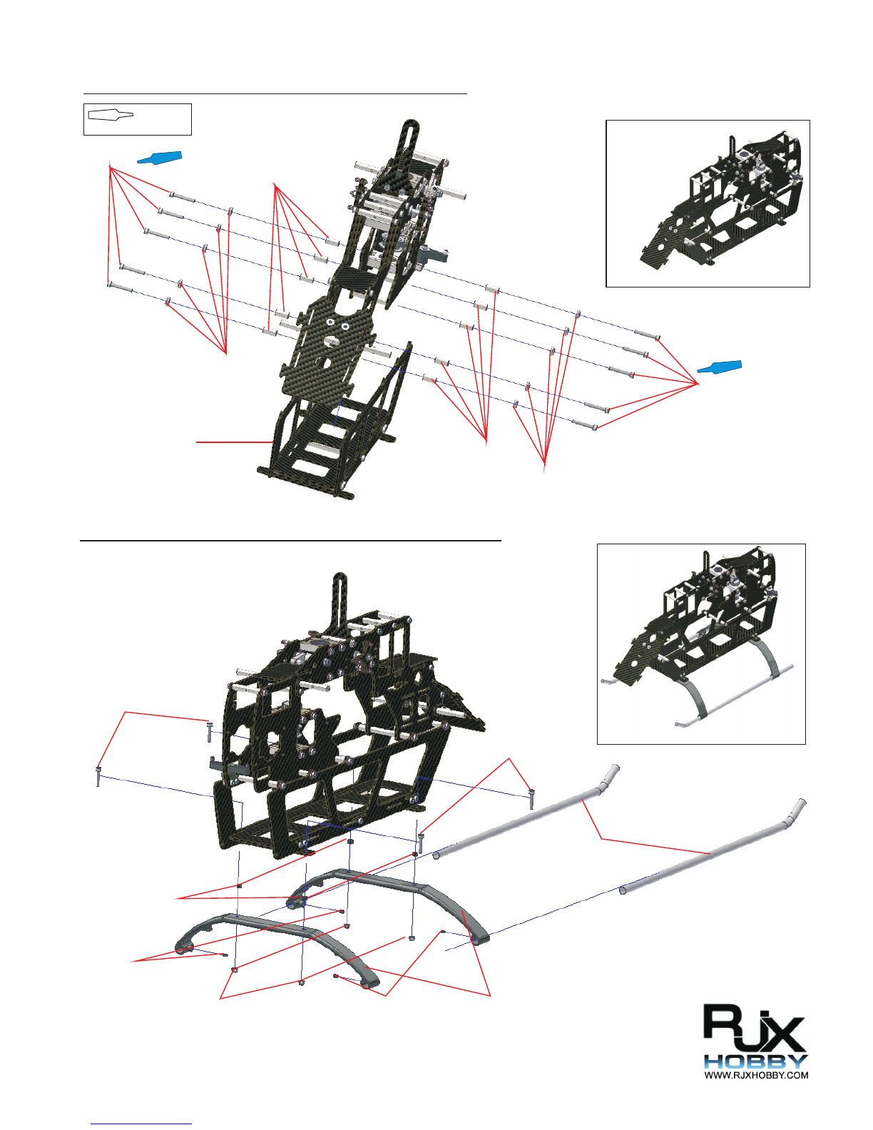
STEP 2-5 Upper Main Frame Assembly
USE THREADLOCK
STEP 2-6 Upper Main Frame Assembly
USE THREADLOCK
View of the completed Assembly
Nick Arm
M4x4
Set Screw ( Do not use Threadlock for later adjustment)
Swashguide
F4x8x3 Bearing
CCPM Shaft
M4x4
Set Screw
CCPM Arm
M3 Lock Nut
M3x8
Front CCPM Arm
F4x8x3 Bearing
M4 Lock Nut M3x8
M4 Lock Nut
M3 Lock Nut
Finish Cap
Finish Cap
Front CCPM Arm
M3x8
M3x10
Canopy Mount
Canopy Mount
M3x10
M3x8
32mm Crossmember
Assembled in Step 1-8
IMPORTANT:
Do NOT over thighten the M4 Lock Nut to ensure the smooth
opperation of the assembly.
4x6x1 Washer
A9
STEP 2-7 Main Frame Assembly
STEP 2-8 Landing Skid Attachment
Assempled in Step2-1
USE THREADLOCK
M3x25
Finish Cap
12mm Spacer
12mm Spacer
Finish Cap
M3x25
View of the completed Assembly
View of the completed Assembly
3x5x3 Plastic Washer(4)
M3x4 Set Screw
M3x4 Set Screw
M3 Lock Nut
M3x18
M3x18
Skids
Landing Skid Brace

A10
STEP 3-1 Drive Gear Instalation
USE THREADLOCK
Pinion
M4x4 Set Screw
M4x10 Motor Mount
Brushless Motor
M4x10
View of the completed Assembly
STEP 3-2 Drive Gear Installation
Note:
Do not tighten the two M4x10 screws.
On some motors you can use up to 4
Set Screws to fix the Pinion.
Depending on the KV of the Brushless
Motor the Pinion and/or the Maingear
must be changed to reach a good ratio.
View of the completed Assembly
USE THREADLOCK
M3x10
Finish Cap
M3x10
Finish Cap
Important:
Ensure that the Pinion is inside
the bearing.

A11
STEP 3-3 Drive Gear Instalation
IMPORTANT:
When securing the main shaft, pull it upwards through
the main bearings to eliminate any freeplay. Next press
the main shaft collar firmly onto the upper bearing block
and fix with threadlock the four M4x4 set screws.
NOTE:
DO NOT tighten the Jesus Bolt too much.
If tigthen to much the Tail Gear Housing
could deform.
NOTE:
Insure the bigger hole is
inserted.
M2,5x12 M4x10
4mm Hole Main Shaft
Main Shaft Collar
M2,5x10
Assembled in Step 1-3
M2,5x12
M4x10
USE THREADLOCK
View of the completed Assembly
NOTE:
Depending on Motor and Ratiu selected the distance between main gear and motor position will change.
Ensure to archive a perfect gear mesh.On high power setups, please leave the backslash as samll as possible
without beeing to tight.

A12
STEP 4-1 SWASHPLATE ASSEMBLY
STEP 4-2 WASHOUT ASSEMBLY
NOTE:
There are two position to mount the Jointball.
The outer hole is for faster response.The
inner for less.
View of the completed Assembly
View of the completed Assembly
USE THREADLOCK
USE THREADLOCK
4mm Ballarm (4)
Swash Guide Pin
Washout Base Washout Arm
M2x10 Socket Head Bolt
Jointball
M3x12 Socket Head Bolt
Washer 3x5x1
Washout Arm
NOTE:
Do NOT over tighten the M3x12 Bolts to avoid damge
to the bearings.
9mm Ballarm (3)

STEP 4-3 SWASHPLATE / WASHOUT INSTALLATION
STEP 4-4 SEESAW INSTALLATION
TOP
BOTTOM
IMPORTANT:
Insure the correct direction
View of the completed Assembly
View of the completed Assembly
NOTE:
Attach the two Washoutlinks to the swash plate.
M3x10 Socket Head Bolt
Rotor Stopper
Centerhub
Seesaw
M4x6 Socket Head Bolt
M4x6 Socket Head Bolt
USE THREADLOCK
IMPORTANT:
Do NOT over tighten the M4x6 Socket Head Bolt to fix the
Seesaw.Hard type of thread lock is necessary.
A13
NOTE:
Apply the threadlock inside the Seasaw.
On this way the fix of the screws is enured.

A14
STEP 4-5 MAIN BLADE HOLDER ASSEMBLY
STEP 4-6 MIXER ARM ASSEMBLY
View of the completed Assembly
View of the completed Assembly
Main Blade Holder
M3x6 Socket Head Bolt
Pitch Arm
Mixer Arm
Ball Arm 4mm
NOTE: Assemble 2 sets of the Main Blade Holder.
Detailed adjustments in Step 4-13.
NOTE: Assemble 2 sets of this mixer arm
NOTE:
Don´t use in this step threadlock to fix the Ball arm.
IMPORTANT:
Mixer settings are explained in Step 4-13 more detailed.

A15
STEP 4-7 MAIN ROTOR HEAD ASSEMBLY
STEP 4-8 MAIN ROTOR HEAD ASSEMBLY
View of the completed Assembly
Spindle
Damper
Spindle Collar
Thrust Washer
Washer 5mm
M5x12 Socket Head Bolt
Thrust Bearing
smaller ID
bigger ID
IMPORTANT:
Check the correct size and way
of installing the Thrust Bearing.
Add grease to the bearing.
USE THREADLOCK NOTE:
Use silicon grease for the dampers.
This also needs to be reaplied as part
of your on going maintenace (after
about 30 to 40 flights) to ensure that
the dampers not getting dry.
View of the completed Assembly
4mm Flybar (550mm)
Washer 3x5x2
Ball Arm 9mm
M3x16 Socket Head Bolt
Assembled in Step 4-6
Washer 3x5x1
Flybar Arm
Rotorhead Assembly
NOTE:
Assemble both sides of the Rotor head the same way.
Do NOT use threadlock for later adjustments.
M4x4 Set Screw
GREASE

A16
STEP 4-9 MAIN ROTOR HEAD ASSEMBLY
Phase Ring
Set Screw M3x4
Jesus Bolt M4x8
View of the completed Assembly
M3x14 Socket Head Bolt
Jesus Bolt M4x8
M3x14 Socket Head Bolt
Set Screw M3x4
NOTE:
The size of the linkage rod can variate depending
on the head setup. In the STEP 7-2 will be an
example of setup with the acording sizes of the
linkage rods.
By looking closely, you will notice on the universal
links the letters RJX (on the small) and RJXHOBBY
on the large links. ensure this are always pointed
outside from the ball as shown in the diagram below.
RJX or RJXHOBBY
Link A
Link B
Link C
Use four short links
and two 2x20mm rod
Use four long links and
two 2x25 mm rod
Use four long XL links
and two 2,6x75mm rod
STEP 4-10 CONTROL ROD INSTALLATION
USE THREADLOCK
Other RJX Hobby Toy manuals


Popular Toy manuals by other brands

Maxford USA
Maxford USA de Havilland DH.82 Tiger Moth V2 instruction manual

Fisher-Price
Fisher-Price X7673 instructions

Aerotech
Aerotech tomahawk Assembly and operation instructions

Mattel
Mattel FBT08 instructions

Little Tikes
Little Tikes CRAZY BLENDER 645129 quick start guide

Gigo
Gigo EXPERIMENTS 7335RR manual

Hasbro
Hasbro Transformers Titans Return Titan Master Decepticon Necro & Full-Tilt &... Assembly instructions

Fisher-Price
Fisher-Price CREATIVE COASTER 72690 instructions

Faller
Faller SERVICING AREA ACCESSORIES manual

LEGO
LEGO Home Alone 21330 manual

Compass
Compass 7hv Wiring Tips

Easy-Bake
Easy-Bake Blueberry Muffin Tops Mixes instructions


