RJX Hobby X-Treme 90 User manual

Technical Data:
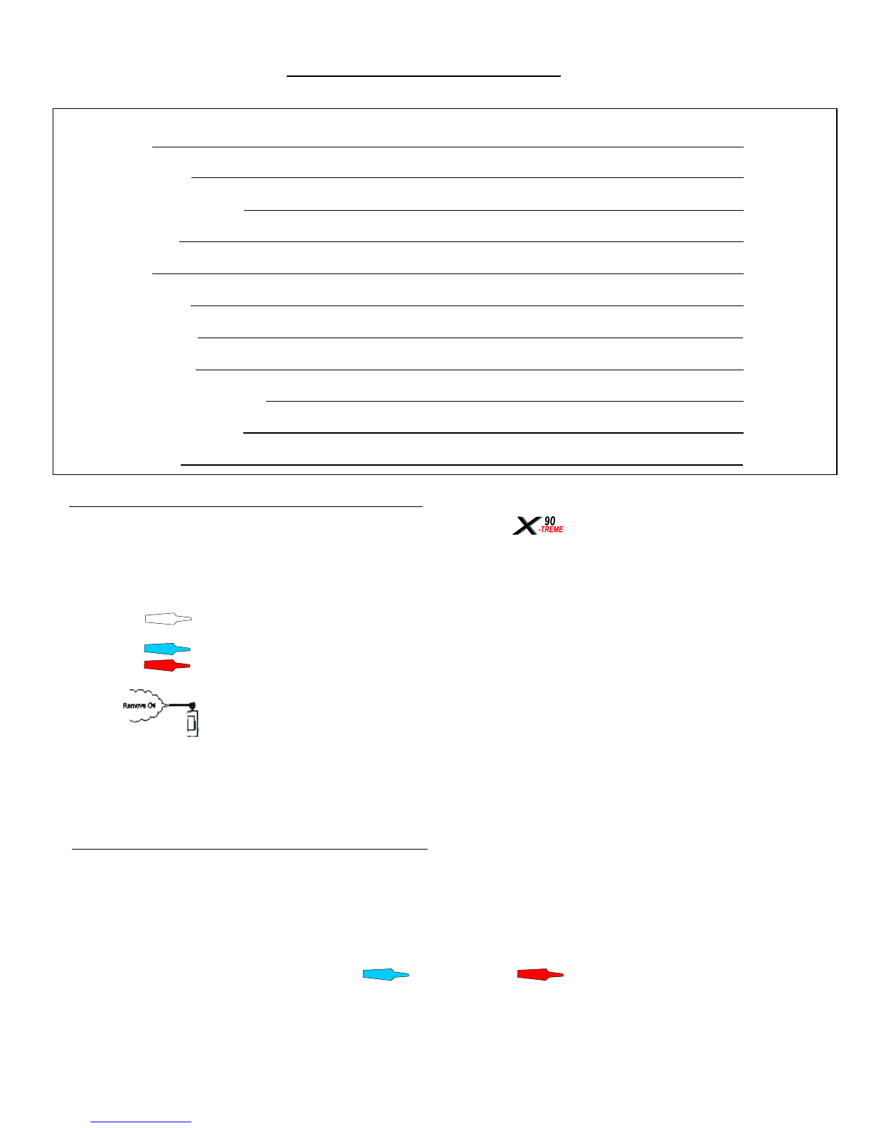
Overall Length
Overall Height
Overall Wide
Main Rotor Diameter
Tail Rotor Diameter
Gear Ratio
Gross Weight
1340 mm
430 mm
210 mm
1690 mm
281 mm
8.1.8:1:4.7 + 8.4.5:1:4.7
4300g - 4600g
PLEASE READ AND UNDERSTAND THE INSTRUCTIONS THOROUGHLY BEFORE ASSEMBLY
INTRODUCTION
Please read this manual carefully. It is essential for the correct assembly of the
For the correct assembly and safe flying, this manual uses this symbol where special attention is required in the assembly of
your model. It is very important that you follow the instructions at these points in the manual. Failure to do so can lead to the loss of
control of the model without warning and the possibility of serious accidents or injury.
NOTE Failing to carry out the instructions at this point in the assembly manual will
probably result in an electronic or mechanical failure occurring without warning..
IMPORTANT Means that special care is required at this point for correct assembly.
Disclaimer:
Whilst every effort has been made to supply the correct information in this manual, The Manufacturer and Distributor
cannot guarantee that the purchaser will interpret or follow these instructions as intended and therefore the
Manufacture and Distributor assumes no liability for damage or claims that may occur from the use/misuse of this
product.
Do not be fooled it is NOT easy to fly R/C Helicopters
It may look easy when watching an experienced pilot flying his model, but perseverance and hours of practice will needed before you
will be able to fly and opperate the model safely. RJX HOBBY suggests you join a club or seek help from an experienced pilot to help
you in your first hops off the ground and then as with all things the more you practice the better you will become. Who knows you could
be the next world champion.
WARNING
The fuel used in model helicopter engines is highly inflammable and poisonous to human beings. For your own safety and that of
others, you should exercise care when handling and storing it. Always read the label on the container and please note the cautions
below.
1. Model helicopter fuel is highly inflammable. Do not smoke or light fires near your fuel.
2. We recommend that you keep your fuel in metal cans or plastic bottles and to store it where there is no risk of fire.
3. Please keep fuel away from the starter battery. It only needs one spark and…..!!!
4. Wipe up spilt fuel immediately. Do not take any chances.
5. Do not leave fuel in the sun or in you car on a hot day.
6. Before refuelling, shut off the engine and wait until it cools down.
7. Always drain the fuel tank of you helicopter at the end of a flying session. It is good practice.
I1
I2
TABLE OF CONTENTS
1. Introducion
2. Table of contents
3. Additional Items Required
4. Tools Required
5. Assembly
6. Servo Installation
7. Servo Adjustment
8. Rotor Head Setup
9. Final Servo and Radio Setup
10. Please read before flight
11. Spare Parts List
I1
I2
I3
I4
A1 - A33
S1-S4
S5-S6
A24
R1-R5
Pf1
SP1 - SP6
This manual contains the detailed instructions to build and set up the . Please follow it to ensure that you
achieve the best performance and mechanical integrity from your finished kit. For those of you who already have
experience of model helicopters, we still suggest that you assemble and adjust your model according to these
instructions for the best results. Please keep your copy of this manual in a safe place and refer to it when replacing
spare parts or upgrading.
Remove oil and grease then apply threadlock. (This applies throughout the manual)
Remove oil and grease. (This applies throughout the manual)
Please refer to the list at the end of this instruction manual when you need spare parts.
Regardless how tight the nuts, bolts and screws are tightened, they will still slowly come loose over a period of time
due to vibration from the helicopter. Should this happen the helicopter will become out of control or severely damaged
causing a very potential dangerouse situation.
We strongly recommend that you apply threadlock to any nuts, bolts or screws that are indicated by these signs.
There are two types of threadlock, blue (soft) and red (hard) . Use blue threadlock on screws
that have to be removed regularly and red threadlock for screws that should be fixed permanently. Clean them
with Alcohol (or similar) before you apply the threadlock.
TO PREVENT LOOSE SCREWS AND BOLTS
HOW TO USE THIS INSTRUCTION MANUAL
Use CA (Superglue or similar) at this point
CA

ADDITIONAL ITEMS REQUIRED TO COMPLETE THE
Choose a CCPM compatible PCM Radio System for
Helicopters with a minimum of 6 channels. Gyro system with
Heading Hold Three large and two small disks or
arms are required
90 Size glow engine,OS 91, YS91 90 Size Muffler (for kits without Muffler)
Helicopter fuel:
15% - 30% Nitro,18% - 23% Oil 1,5V Glow Plug Battery
and glow plug conector Fuel Pumb 12V Electric Starter
Starter Extension Fuel Filter 690mm - 710mm Main Blades (for kits without Blades)
I3

Allen Drivers 1,5mm - 2mm - 3mm - 4mm Phillips Drivers Large,Middle, Small Nut Drivers 4,5mm - 5,5mm - 7mm
Cutter Universal Pliers Scissors
Sandpaper Ball Link Plier Metric Ruler Pitch Gauge
Cyanoacrylate (CA/Superglue) Epoxy 30 Minutes Grease
Ball Link Driver Universal RC Cross Wrench Ball Link Tool
TOOLS REQUIRED (NOT INCLUDED)
I4
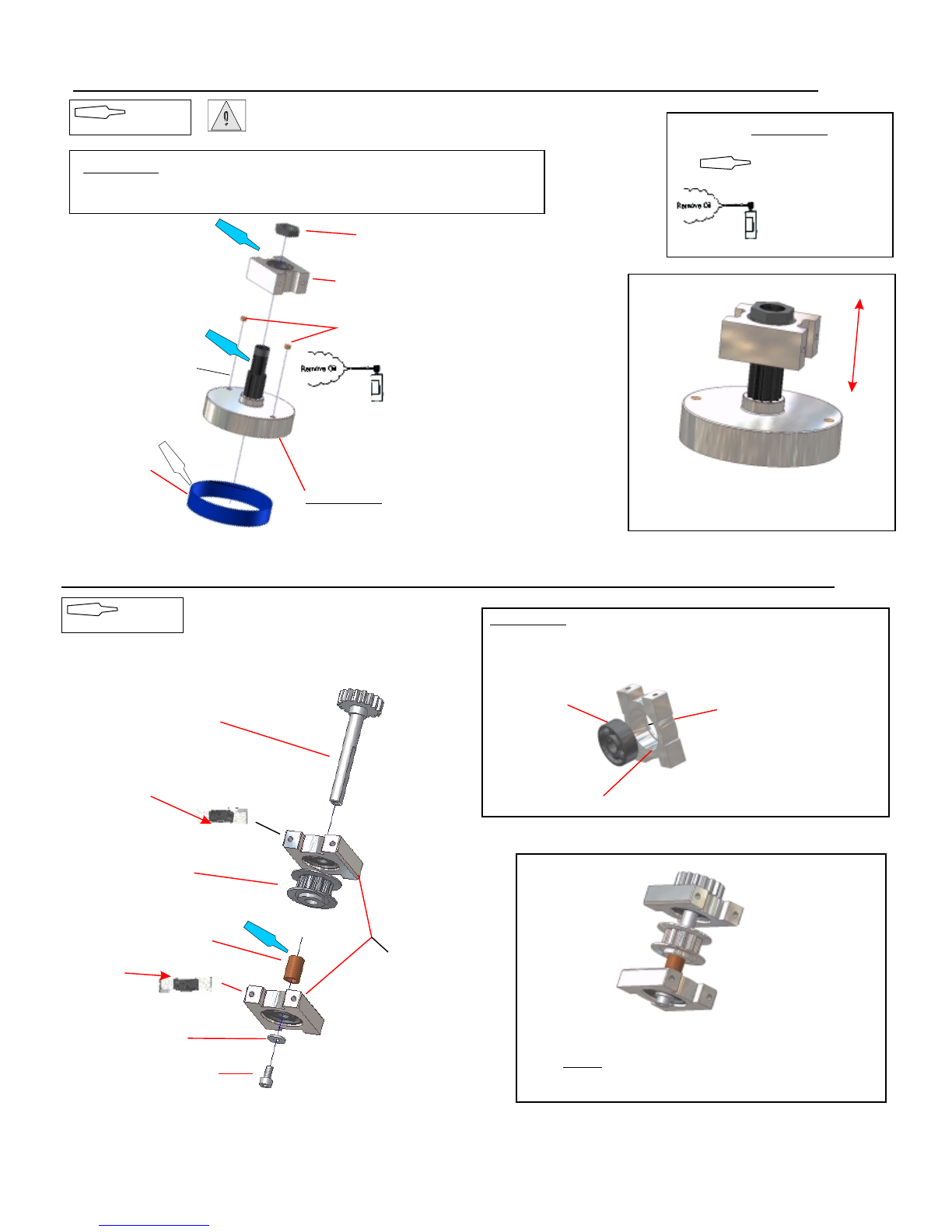
STEP 1-2B Tail Drive Pinion Gear Assembly (Belt Version)
STEP 1-1 Clutch Bell / Starter Shaft BB Block Assembly
A1
Clutch Bell Assembly
Starter Shaft BB Block
IMPORTANT:
Sand the inside before glueing the clutch liner.
View of the completeAssembly.
Check that there is no exessive movement
up and down and the assembly rotated freely.
Apply threadlock to the pinion gear and
install in place until the threadlock has
completely set.
USE THREADLOCK
CLEAN FROM OIL
AND GREASE
IMPORTANT:
Flange
Without Flange
Bearing
IMPORTANT:
One end of the BB Block is machined with a flange to retain the
Bearing. Assemble it as shown in the diagramm below.
With Flange facing downwards
Tail Drive Pinion BB Block
Tail Drive Pinion
M3 Washer
M3x6 Socket Head Bolt
Front Tail Pulley
View of the completed assembly
USE THREADLOCK
IMPORTANT: Before assembling sand the inner side of the clutch bell and the side
from the clutch liner you will glue in.Use 30 minutes EPOXY to glue the liner in the
clutch bell and fix them with some clips to ensure a good and thight fit of the liner.
Magnet´s for Governor:
Install them by using 30 minute
EPOXY.
Special Nut
Clutch Liner
With Flange facing upwards
NOTE: DON´T use threadlock for the M3x6 Screw
for later attach the belt.
Copper Spacer
USE THREADLOCK
EPOXY

STEP 1-2TT Tail Drive Pinion Gear Assembly (TT Version)
Tail Drive Pinion
M3 Washer
M3x6 Socket Head Bolt
M3x4 Setscrew
12mm Pin
Output Shaft
19TAlloy Beevel Gear
19T Delrin Beevel Gear
M3x4 Setscrew
5x7x1 Washer
5x7x1 Washer
(if needed)
TT Gear Box
View of the completeAssembly.
Check that the gearmesh is correctly
(if necesary add a 0.2mm Nylon Washer) and
the assembly rotated freely but without play.
USE THREADLOCK
STEP 1-3 Drive Gear Assembly
M3x6 Socket Head Bolt
90/93T Helical Main Gear
M3x6 Counter Socket Head Bolt
80T Tail Drive Gear
Tail Drive Gear Housing
Autorotation Shaft
Autorotation Spacer
IMPORTANT:
Stepped side facing downward
and entering completly inside
the bearing.
View of completeAssembly
CAUTION:
Clean off any dust on drive gears.
Add grease to the one way bearing,
to ensure smooth opperation.
Don´t fix the four M3x6 bolts before
having all four in place.
USE THREADLOCK
IMPORTANT: Start assembly with the OUTPUT SHAFT.
A2
NOTE:
Use the 90T main gear for OS91 and YS91SR.
The 93T is for use with YS91ST.
IMPORTANT:
Add 0,2mm Nylon washer to
reach a PLAYLESS Gear mesh.
Check that the two gears are
perfectly aligned (shown in the
picture on the right).Stay on the
tide side of the gear mesh.
A exesive play can strip the
Delrin gear.

STEP 1-4 Fuel Tank and AUX Tank Assembly
Main Tank
Fuel Clunk
Silicon Tube ca.87mmTank Grommet
Tank Nipple
Tank Nipple
Tank Grommet
Silicon Tube 40mm
Fuel Clunk
AUX Tank
To Main Tank
Exhaust pressure nipple
IMPORTANT:
Make sure that the Fuel Clunk can move freely inside the tank.
Be sure to replace the silicon fuel tubing inside the Main
and AUX Tank regularly.
NOTE:
Cut the fuel tubing to length using a hobby knife.
So there is a clean cut.
M5 Special Nut
NOTE:
For easy assambling of the Exhaust Pressure Nipple
use a thin cable binder passing it throug the nipple.
STEP 1-5 Swash Control Lever Assembly
M2x8 Socket Head Bolt
Jointball
Control Lever
View of the completedAssembly
Flange facing downward
NOTE: Assembly 2 sets of this lever
USE THREADLOCK
A3

A4
STEP 1-6 Swash Control Assembly
USE THREADLOCK
M2x6 Socket Head Bolt
Joinball
4mm Ball Arm
Nick Arm
Swash Lever
View of the completedAssembly
STEP 1-7 Front Tail Arm Assembly
USE THREADLOCK
M2x10 Socket Head Bolt
M3x20 Socket Head Bolt
Joinball
Control Lever
Washer 3x5x1
Leverblock
CAUTION:
Do NOT over tighten the M3x20 bolts
to avoid breaking the bearings.
M4x4 Setscrew
View of the completedAssembly

A5
STEP 1-8 Battery Tray Assembly
USE THREADLOCK
M3x6 Countersunk Head Bolt
Battery Tray
View of the completedAssembly from both side
Special Crossmember
BATTERY TRAY inside the bag of the MAIN FRAME
STEP 1-9 Canopy Stands
32mm Crossmember
M3x8 Socket Head Bolt
Breakoff
View of the completedAssembly
NOTE: Assemble 4 sets
BREAKOFF are inside the bag of the MAIN FRAME
USE THREADLOCK

A6
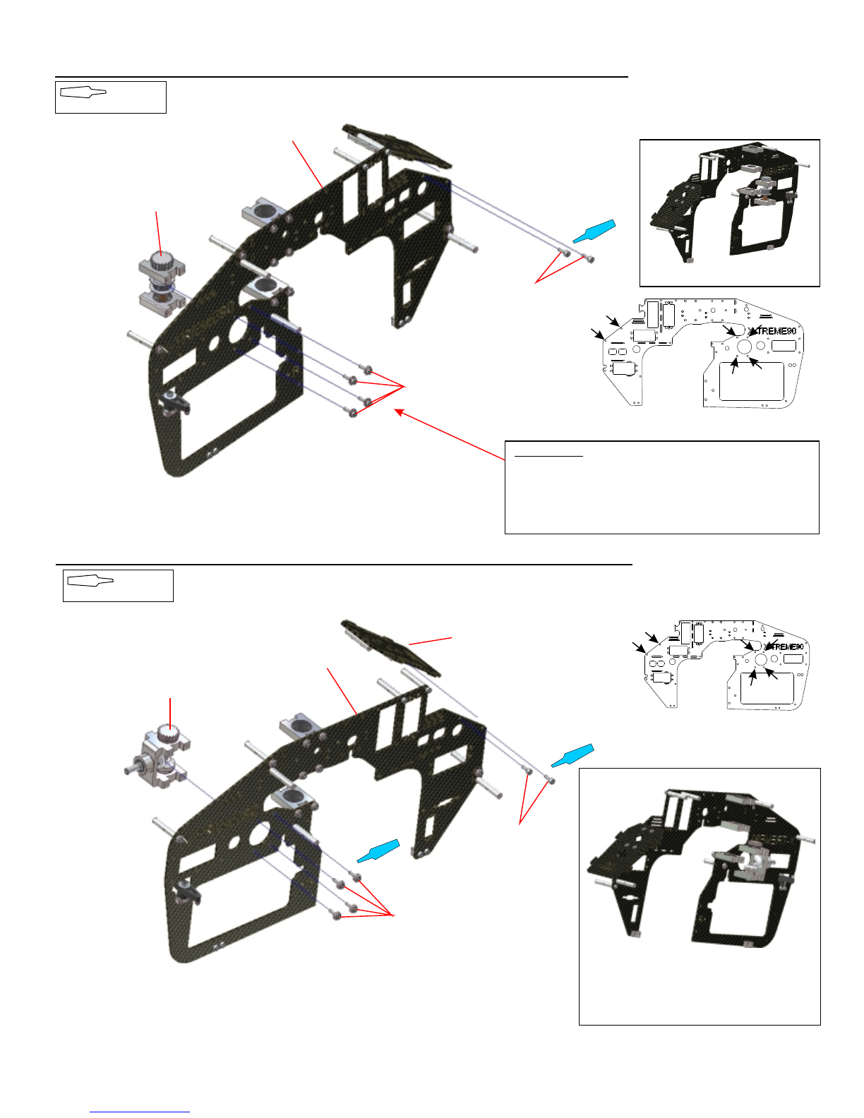
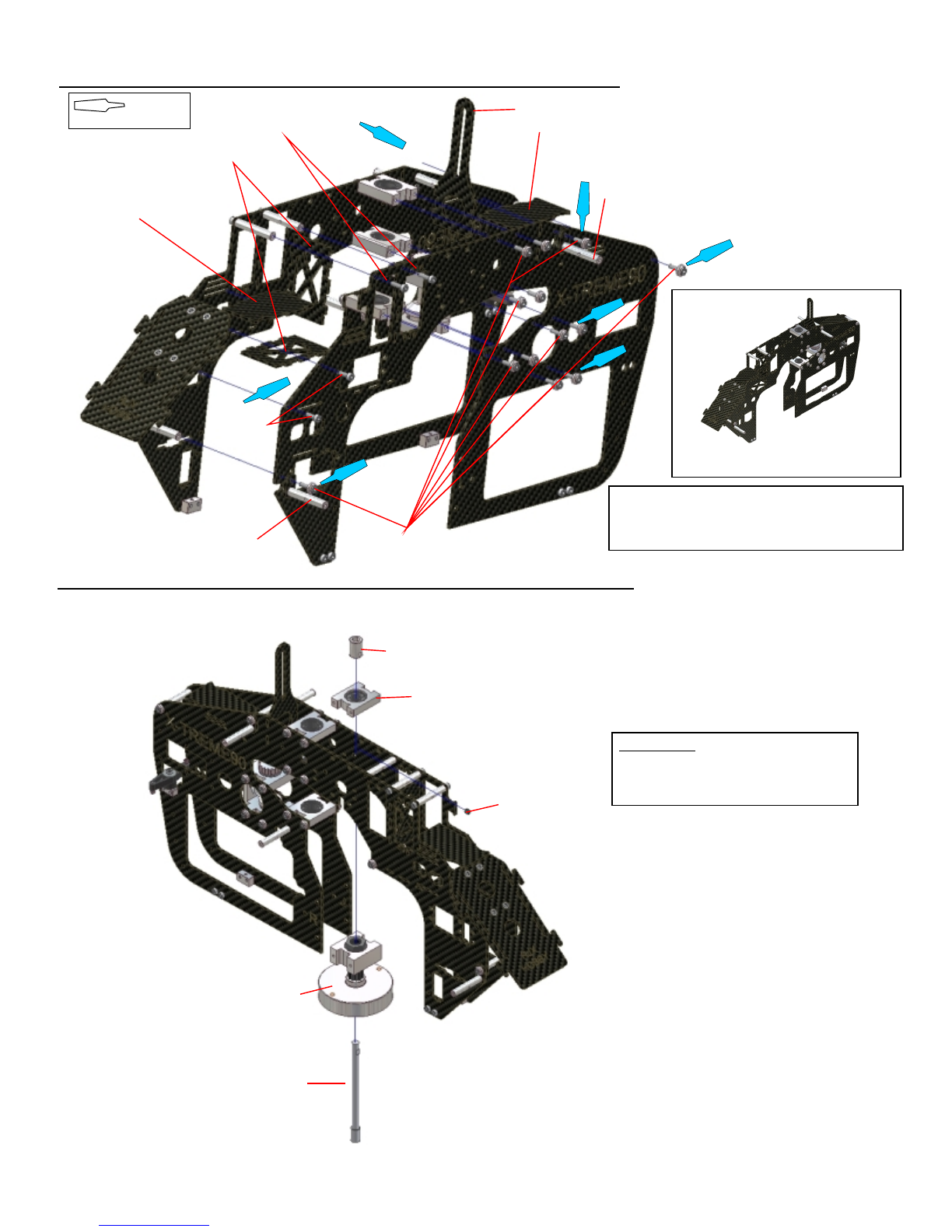
STEP 2-1 Main Frame Assembly (TT+Belt)
Main Frame Right
Bottomplate Mounting Block M3x8 Socket Head Bolt
Main Frame Left
M3x8 Socket Head Bolt
Bottomplate Mounting Block CAUTION:
The main frame sides are NOT the same. Look at
the L and R writing cutout on the frame sides to
ensure that you have the correct sides.Assemble
both sides like shown in the diagram.
USE THREADLOCK
STEP 2-2 Main Frame Assembly (TT+Belt)
Main Shaft Bearing Block
Assembled in Step 1-9
M3x8 Socket Head Bolt
Assembled in Step 1-9
M3x10 Socket Head Bolt
with Finish Cap´s
M3x10 Socket Head Bolt
32mmCrossmember
Main Frame Right
(Assembled in STEP 2-1)
NOTE:
Place the Frame on a flat surface to mount the Bearing Blocks
and the Crossmember.
IMPORTANT:
DO NOT use Threadlock in this stage for the Bearing Blocks
for later adjustment. It will be indicated when Threadlock
should be used.
USE THREADLOCK
TOP
Flange face
downward
Flange face
downward
Flange face
upward
IMPORTANT:
Holes to be used
Bottomplate Mounting Block
M3x8 Socket Head Bolt
M3x8 Socket Head Bolt
Holes to be used
Assembled in Step 1-7
M3x10 Socket Head Bolt
with Finish Cap
32mmCrossmember
32mmCrossmember
R
L
A7
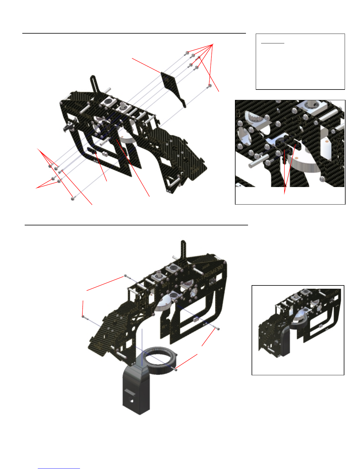
STEP 2-3B Main Frame Assembly (Belt Version)
M3x10 Socket Head Bolt
with Finish Cap´s
IMPORTANT:
DO NOT use Threadlock in this stage for the Bearing Blocks,
for later adjustment. It will be indicated when Threadlock
should be used.
M3x8 Socket
Head Bolt
Main Frame Right (Assembled in Step 2-2)
View of the completedAssembly
USE THREADLOCK
STEP 2-3TT Main Frame Assembly (TT Version)
USE THREADLOCK
View of the completedAssembly
M3x8 Socket head Bolt
Holes to be used
Tail Drive (Assembled in Step 1-2B)
Battery Tray
(Assambled in Step 1-8)
M3x10 Socket Head Bolt
with Finish Cap´s
TT Tail Drive (Assembled in Step 1-2TT)
Main Frame Right (Assembled in Step 2-2)
Holes to be used
A8
STEP 2-4 Main Frame Assembly (TT+Belt)
USE THREADLOCK
STEP 2-5/1 Main Frame Assembly (TT+Belt)
M3x10 Socket Head Bolt with Finishcup
Front Gyro Mount
Rear Gyro Mount
Starter Shaft
Assembled in Step 1-2
6mm Bearing Block
IMPORTANT:
DO NOT tiden the M4x4 Set Screw..
View of the completedAssembly
Canopy Mount
Canopy Standoff
M3x8 Socket
Head Bolt
Frame Stiffner
M3x10 Socket Head Bolt
NOTE:
DO NOT use thread lock on the Bolts for the Main
Shaft BB Blocks. Will be indicated in later step.
Hex Starter Coppler
M4x4 Set Screw
Swash Guide
A9
STEP 2-5/2 Main Frame Assembly (TT+Belt)
STEP 2-6 Clutch Sytem Assembly (TT+Belt)
M3x10 Socket Head Bolt
Standoff
CAUTION:
Depending on witch Engine Type used
must be selected diferent Ratio Mounts.
For Os91 Types and YS 91 SR must be
used the Mount with 90 indicated for a
8,18 Ratio.
For a YS 91 ST Engine the 93 one for a
Ratio from 8,45.
3x16 Special Spckegt Head Bolt
M4 Lock Nut
Fan Shroud
View of the completedAssembly
M3 Lock Nut
M3x10 Socket Head Bolt with Finishcup
Ratio Modul Right
(90T Main Gear)
Mount for Sensor
(Gv1 FUTABA)
M3x10 Socket Head Bolt
M3x14 Socket Head
Bolt with Finishcup
Ratio Modul Left
(90T Main Gear)
Use this mounts for other Type
of Governors
3x16 Special Spckegt Head Bolt
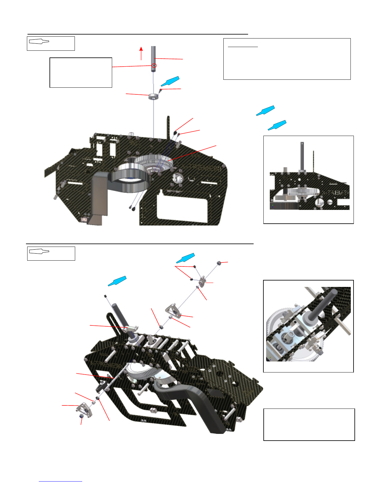
STEP 2-7 Main Frame Assembly (TT+Belt)
USE THREADLOCK
Main Shaft
M2,5x10 Socket Head Bolt
Main Shaft Collar
M4x8 Socket Head Bolt (2)
M2,5x10 Socket Head Bolt (2)
Autorotacion Unit
View of the completedAssembly
STEP 2-8 CCPM Sytem Assembly (TT+Belt)
M4x4 Set Screw
M4x4 Set Screw
M4 Lock Nut
M4 Lock Nut
Washer 4x6x1
Nick Lever
CCPM Ballcrank
Spacer 4x6x4
Bearing F4x8x3
Bearing F4x8x3
CCPM Ballcrank
Spacer 4x6x4
CCPM Shaft
Nick Arm
View of the completedAssembly
USE THREADLOCK
NOTE:
DO NOT overtiden the M4 Lock Nut.
Check the Armes work smooth and
without play.
NOTE:
Ensure the correct way
of the main shaft.Hole with
larger distance to the end
first inside.
IMPORTANT:
When securing the main shaft, pull it upwards through
the main bearings to eliminate any freeplay. Next press
the main shaft collar firmly onto the upper bearing block
and fix with threadlock the four M4x4 set screws.
A10

STEP 2-9 Main Tank (Engine WITHOUT Tank Preasure)
USE THREADLOCK
Main Tank
M3x10 Socket Head Bolt
with Finishcap
Main Shaft Collar
32mm Crossmember
Tank Rubber
View of the completedAssembly
View of the completedAssembly
NOTE:
DO NOT overtiden the M4 Lock Nut.
Check the Armes work smooth and
without play.
CA
CA
Tank Rubber
M3x10 Socket Head Bolt
with Finishcap
STEP 2-9/1 Main Tank (Engine WITH Tank Preasure)
USE THREADLOCK
Tank Rubber
M3x40 Socket Head Bolt
Finishcap
32mm CrossmemberM3x10 Socket Head Bolt
with Finishcap
Tank Plate
25mm Spacer
NOTE:
Use CA to fix the Tank Rubbers
in the corners of the Main Frame.
NOTE:
Use CA to fix the Tank Rubbers
in the corners of the Main Frame.
CA
Tank Rubber
CA
A11
STEP 2-10 Main Frame Assembly (TT+Belt Version)
USE THREADLOCK
M3x14 Socket Head Bolt
Landing Strut
Landing Skid Brace
M3 Lock Nut
Skid Holder
NOTE:
Assemble two sets.Do NOT tighten the screws for later adjustment.
Landing Strut
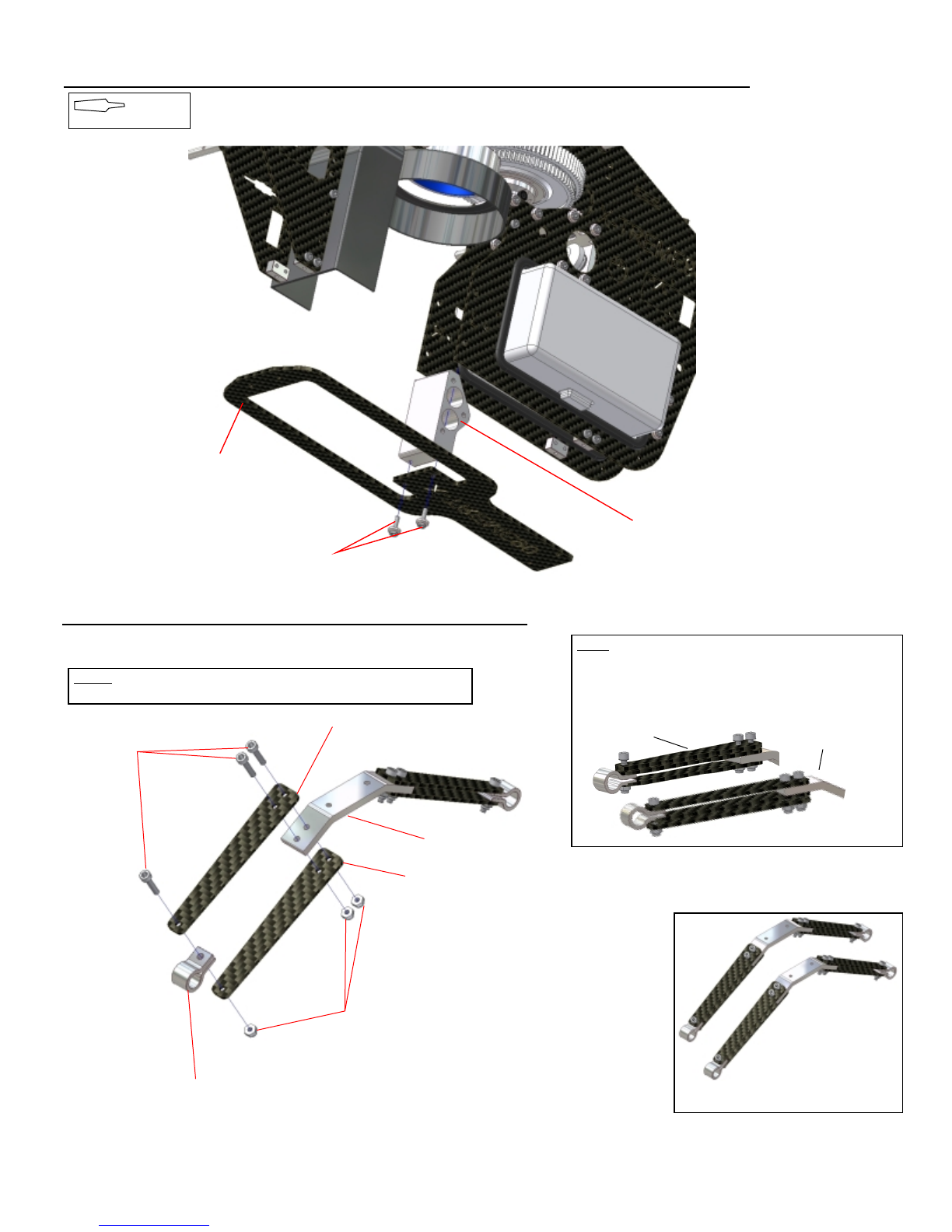
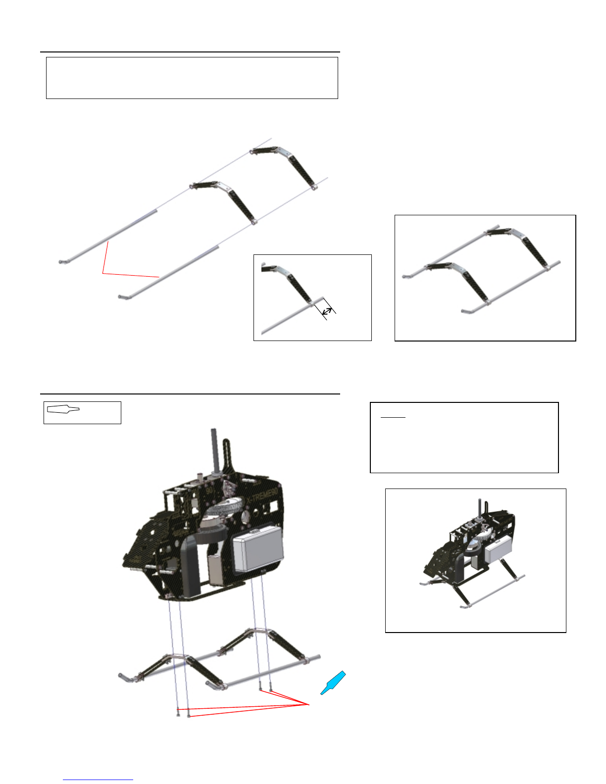
STEP 2-11 Landing Skid Assembly
Note:
For extra strength place a second Landing Strut.On the
top of both sides and the other on the lower part of the
other set. As shown in the diagram below..
To be used in back To be used in front
View of the completedAssembly
Bottom Plate
Engine Mount (Middle)
M3x10 Socket Head Bolt
with Finish caps
A12
A13
STEP 2-13 Landing Gear Assembly
View of the completedAssembly
Landing Skids
NOTE:
Place the complete assembly on a flat surface.Do NOT tighten the screws yet
ca. 20mm
View of the completedAssembly
M3x14 Socket Head Bolt
STEP 2-12 Landing Gear Assembly
NOTE:
Place the complete frame after assembling on a
flat surface and tighten the screws from the
Landingskid assembly.Insure that the the skids
are flat on the surface.
USE THREADLOCK

A14
STEP 3-1 CLUTCH/COOLING FAN ASSEMBLY
Drive Nut
( incl. with OS Engine)
Cooling Fan Hub
Cooling Fan
M3x6 Socket Head Bolt
Engine Washer
(incl. with OS Engine)
USE THREADLOCK
NOTE:
If a drive washer is included with the engine you willl need
to remove this. (Contact your dealer for information). For
OS Engines, the thin black washer supplied will be used
under the bottom collet.
The Fanhub may be a little tight on the crankshaft
so a good push may needed.
Note that the black washer goes on first if you are
using a OS Engine.
Assemble as shown in the diagram and secure
the engine nut tightly. It is suggested that you
use a piece of towel or cloth wrapped around
the engine and the fan hub so that you can
hold them tightly when doing this operation.
After tiden the Engine Nut tide the two
M2,5x10 Socket Head Bolts.
IMPORTANT:
Be sure to keep the clutch shoe square to the fan hub
when tightening the securing bolts.
Tighten each bolt a little at time and keep checking as you proceed.
Clutch
M4x10 Socket Head Bolt
M2,5x10 Socket Head Bolt
IMPORTANT:
For OS 91 and YS 91 SR use the 90T Main Gear and Ratio Mounts.
For YS 91 ST use the 93T Main Gear and 93 Ratio Mounts.
A15
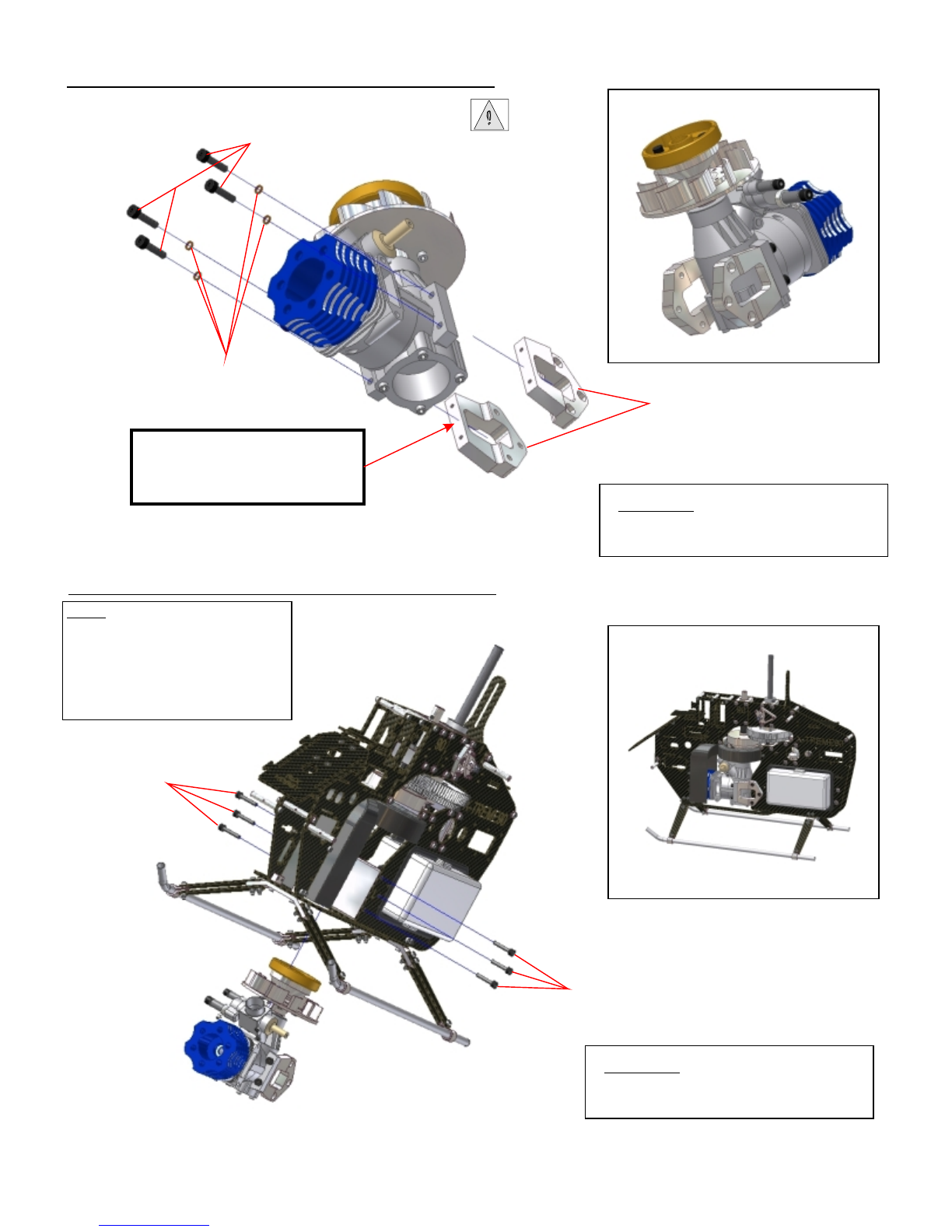
STEP 3-2 ENGINE INSTALATION
STEP 3-3 ENGINE INSTALATION
M4x16 Socket Head Bolt
IMPORTANT:
Do NOT tighten the srews for later alignment.
Spring Washer
Engine Mount L/R
View of the completedAssembly
IMPORTANT:
For the 8,45 Ratio you need to add the
two delivered 1.5mm Spacers between
the Engine and the Engine Mount
View of the completedAssembly
M4x20 Socket Head Bolt
M4x20 Socket Head Bolt
IMPORTANT:
Do NOT tighten the srews for later alignment.
NOTE:
It is possible that you may have to
remove the carburator to insert the
engine.After the engine has passed
through the bottom plate reinstall the
carburator before inserting the engine
completly.
Table of contents
Other RJX Hobby Toy manuals


Popular Toy manuals by other brands

HOMCOM
HOMCOM 350-081 manual

Fisher-Price
Fisher-Price Ford MUSTANG J4390 Owner's manual & assembly instructions

Multiplex
Multiplex ParkMaster 3D Building instructions

THE WORLD MODELS
THE WORLD MODELS Extra 300 EP instruction manual

Fisher-Price
Fisher-Price 71997 instructions

TILLIG BAHN
TILLIG BAHN 03940 manual


