RKI 65-2481RK User manual

RKI Instruments, Inc.
www.rkiinstruments.com
65-2481RK
Multi Point Detector
Operator’s Manual
Part Number: 71-0204RK
Revision: A
Released: 8/2/11

65-2481RK Multi Point Detector
WARNING
Read and understand this instruction manual before operating
detector. Improper use of the detector could result in bodily harm
or death.
Periodic calibration and maintenance of the detector is essential
for proper operation and correct readings. Please calibrate and
maintain this detector regularly! Frequency of calibration
depends upon the type of use you have and the sensor types.
Typical calibration frequencies for most applications are between
3 and 6 months, but can be required more often or less often
based on your usage.

65-2481RK Multi Point Detector
Product Warranty
RKI Instruments, Inc. warrants gas alarm equipment sold by us to be free from defects in
materials, workmanship, and performance for a period of one year from date of shipment
from RKI Instruments, Inc. Any parts found defective within that period will be repaired
or replaced, at our option, free of charge. This warranty does not apply to those items
which by their nature are subject to deterioration or consumption in normal service, and
which must be cleaned, repaired, or replaced on a routine basis. Examples of such items
are:
Warranty is voided by abuse including mechanical damage, alteration, rough handling, or
repair procedures not in accordance with the operator’s manual. This warranty indicates
the full extent of our liability, and we are not responsible for removal or replacement costs,
local repair costs, transportation costs, or contingent expenses incurred without our prior
approval.
THIS WARRANTY IS EXPRESSLY IN LIEU OF ANY AND ALL OTHER
WARRANTIES AND REPRESENTATIONS, EXPRESSED OR IMPLIED,
AND ALL OTHER OBLIGATIONS OR LIABILITIES ON THE PART OF
RKI INSTRUMENTS, INC. INCLUDING BUT NOT LIMITED TO, THE
WARRANTY OF MERCHANTABILITY OR FITNESS FOR A
PARTICULAR PURPOSE. IN NO EVENT SHALL RKI INSTRUMENTS,
INC. BE LIABLE FOR INDIRECT, INCIDENTAL, OR CONSEQUENTIAL
LOSS OR DAMAGE OF ANY KIND CONNECTED WITH THE USE OF
ITS PRODUCTS OR FAILURE OF ITS PRODUCTS TO FUNCTION OR
OPERATE PROPERLY.
This warranty covers instruments and parts sold to users by authorized distributors,
dealers, and representatives as appointed by RKI Instruments, Inc.
We do not assume indemnification for any accident or damage caused by the operation of
this gas monitor, and our warranty is limited to the replacement of parts or our complete
goods.
a) Absorbent cartridges d) Batteries
b) Pump diaphragms and valves e) Filter elements
c) Fuses

65-2481RK Multi Point Detector
Table of Contents
Overview . . . . . . . . . . . . . . . . . . . . . . . . . . . . . . . . . . . . . . . . . . . . . . . . . . . . . . . . . . . . . . . . . . . 1
Specifications. . . . . . . . . . . . . . . . . . . . . . . . . . . . . . . . . . . . . . . . . . . . . . . . . . . . . . . . . . . . . . . . 1
Description. . . . . . . . . . . . . . . . . . . . . . . . . . . . . . . . . . . . . . . . . . . . . . . . . . . . . . . . . . . . . . . . . . 3
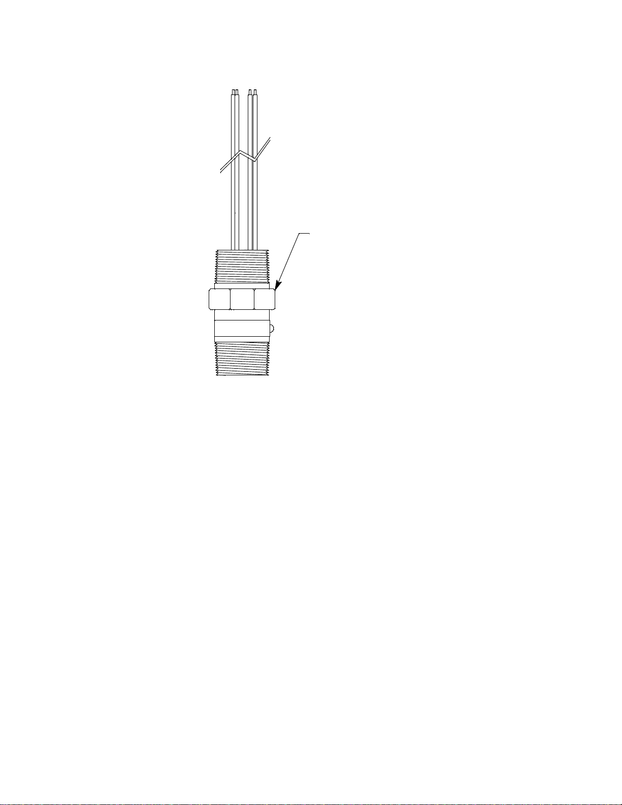
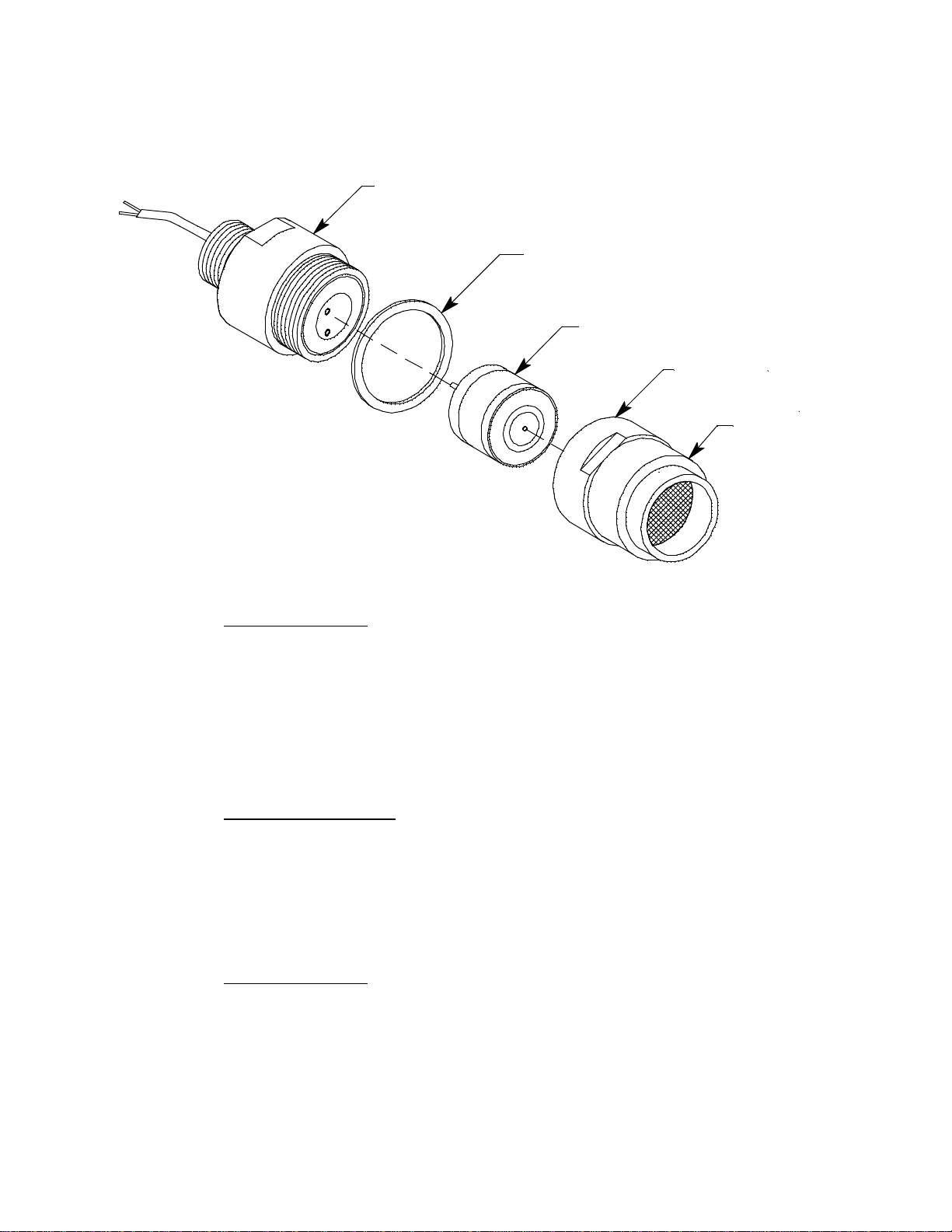
Detectors. . . . . . . . . . . . . . . . . . . . . . . . . . . . . . . . . . . . . . . . . . . . . . . . . . . . . . . . . . . . . . . . . . . . . . . . . . . . . 3
Conduit Seal . . . . . . . . . . . . . . . . . . . . . . . . . . . . . . . . . . . . . . . . . . . . . . . . . . . . . . . . . . . . . . . . . . . . . . . . . 7
Junction Box. . . . . . . . . . . . . . . . . . . . . . . . . . . . . . . . . . . . . . . . . . . . . . . . . . . . . . . . . . . . . . . . . . . . . . . . . . 7
Installation . . . . . . . . . . . . . . . . . . . . . . . . . . . . . . . . . . . . . . . . . . . . . . . . . . . . . . . . . . . . . . . . . . 8
Mounting the Multi-Point Detector . . . . . . . . . . . . . . . . . . . . . . . . . . . . . . . . . . . . . . . . . . . . . . . . . . . . . . 8
Wiring the Multi-Point Detector to a Controller . . . . . . . . . . . . . . . . . . . . . . . . . . . . . . . . . . . . . . . . . . 10
Startup. . . . . . . . . . . . . . . . . . . . . . . . . . . . . . . . . . . . . . . . . . . . . . . . . . . . . . . . . . . . . . . . . . . . . 13
Introducing Incoming Power . . . . . . . . . . . . . . . . . . . . . . . . . . . . . . . . . . . . . . . . . . . . . . . . . . . . . . . . . . 13
Setting the Zero (Fresh Air) Reading. . . . . . . . . . . . . . . . . . . . . . . . . . . . . . . . . . . . . . . . . . . . . . . . . . . . 13
Maintenance. . . . . . . . . . . . . . . . . . . . . . . . . . . . . . . . . . . . . . . . . . . . . . . . . . . . . . . . . . . . . . . . 14
Preventive Maintenance . . . . . . . . . . . . . . . . . . . . . . . . . . . . . . . . . . . . . . . . . . . . . . . . . . . . . . . . . . . . . . 14
Troubleshooting . . . . . . . . . . . . . . . . . . . . . . . . . . . . . . . . . . . . . . . . . . . . . . . . . . . . . . . . . . . . . . . . . . . . . 16
Replacing Components of the Multi-Point Detector. . . . . . . . . . . . . . . . . . . . . . . . . . . . . . . . . . . . . . . 17
Calibration, LEL, H2S and CO Detectors . . . . . . . . . . . . . . . . . . . . . . . . . . . . . . . . . . . . . . . 22
Preparing for Calibration. . . . . . . . . . . . . . . . . . . . . . . . . . . . . . . . . . . . . . . . . . . . . . . . . . . . . . . . . . . . . . 22
Setting the Zero Reading . . . . . . . . . . . . . . . . . . . . . . . . . . . . . . . . . . . . . . . . . . . . . . . . . . . . . . . . . . . . . . 23
Setting the Response Reading. . . . . . . . . . . . . . . . . . . . . . . . . . . . . . . . . . . . . . . . . . . . . . . . . . . . . . . . . . 23
Returning to Normal Operation. . . . . . . . . . . . . . . . . . . . . . . . . . . . . . . . . . . . . . . . . . . . . . . . . . . . . . . . 23
Calibration, Oxygen Detector. . . . . . . . . . . . . . . . . . . . . . . . . . . . . . . . . . . . . . . . . . . . . . . . . 24
Preparing for Calibration. . . . . . . . . . . . . . . . . . . . . . . . . . . . . . . . . . . . . . . . . . . . . . . . . . . . . . . . . . . . . . 24
Setting the Fresh Air Reading. . . . . . . . . . . . . . . . . . . . . . . . . . . . . . . . . . . . . . . . . . . . . . . . . . . . . . . . . . 24
Setting the Zero Reading . . . . . . . . . . . . . . . . . . . . . . . . . . . . . . . . . . . . . . . . . . . . . . . . . . . . . . . . . . . . . . 25
Returning to Normal Operation. . . . . . . . . . . . . . . . . . . . . . . . . . . . . . . . . . . . . . . . . . . . . . . . . . . . . . . . 25
Parts List . . . . . . . . . . . . . . . . . . . . . . . . . . . . . . . . . . . . . . . . . . . . . . . . . . . . . . . . . . . . . . . . . . . 26

65-2481RK Multi Point Detector • 1
Overview
This manual describes the 65-2481RK multi point direct connect detector. This manual
also describes how to install, start up, maintain, and calibrate the detector when it is used
with a gas monitoring controller. A parts list at the end of this manual lists replacement
parts and accessories for the detector.
Specifications
WARNING: Do not use this product in a manner not specified in this instruction
manual.
Table 1 lists specifications for the multi-point detector.
Table 1: Specifications
Target Gas 65-2481RK: LEL/O2/H2S/CO, methane calibration standard for
LEL
65-2481RK-01: LEL (IR CH4)/O2/H2S/CO, methane calibration
for LEL
65-2481RK-02: LEL (IR HC)/O2/H2S/CO, propane calibration for
LEL
*Note: Since the 65-2481RK is a direct connect detector, the
calibration is done at the controller.
Area Classification Explosion proof for Class I, Groups B, C, and D
Sampling Method Diffusion
Detection Range LEL: 0 to 100 %LEL (lower explosive limit)
O2: 0 to 25 %volume
H2S: 0 to 100 ppm (parts per million)
CO: 0 to 300 ppm (parts per million)
Response Time 90% in 30 seconds
Accuracy Catalytic Combustible Gas:
± 5% of reading or ± 2% LEL (whichever is greater)
IR Combustible Gas:
± 5% of reading or ± 2% of full scale (whichever is greater)
Oxygen:
± 0.5% O2
Hydrogen Sulfide:
± 5% of reading or ± 2 ppm H2S (whichever is greater)
Carbon Monoxide:
± 5% of reading or ± 5 ppm CO (whichever is greater)
Operating Temperature 23°F to 104°F (-5°C to 40°C)

2 • 65-2481RK Multi Point Detector
NOTE: The following symbol on the detector label is a caution to the user to refer to this
documentation for installation and operation instructions:
WARNING: When using the 65-2481RK, you must follow the instructions and warnings
in this manual to assure proper and safe operation of the 65-2481RK and to
minimize the risk of personal injury. Be sure to maintain and periodically
calibrate the 65-2481RK as described in this manual.
!

65-2481RK Multi Point Detector • 3
Description
This section describes the multi-point detector. It consists of the detectors, the terminal
strips, the conduit seal, and the junction boxes.
Detectors
This section describes the components of the various detectors that are used with each
model of the 65-2481RK.
61-0140RK LEL Detector
Figure 1: 61-0140RK LEL Detector Component Location
The combustible gas detector is a catalytic type detector that produces an electrical output
that corresponds to the detection range. It is packaged in a 1/2 inch NPT nipple with a
sintered metal flame arrestor on one end allowing ambient air to diffuse into the detector.
The flame arrestor also contains any sparks which may occur within the detector. The 1/2
inch NPT mounting threads at the top of the detector allow you to install it in the bottom
conduit hub of the junction box with the use of a 3/4 in. x 1/2 in. NPT reducer. A
rainshield screws onto the bottom of the detector (flame arrestor end). The rainshield
helps protect the detector from rain and debris in the monitoring environment. Four color-
coded leads extend from the top of the detector. The leads allow you to connect the
detector to the terminal block.
LEL Detector

4 • 65-2481RK Multi Point Detector
61-0190RK IR LEL Detector
Figure 2: 61-0190RK IR LEL Detector Component Location
The infrared LEL detector is made up of a miniature infrared combustible gas LEL
detector housed and encapsulated in a pipe nipple. The pipe nipple has 3/4” NPT threads
on each end and a 1 1/4” hex that allows removal or installation of the detector with a
wrench. A porous flame arrestor that is coated with a hydrophobic film that repels liquids
is on one end of the detector and allows sample gas to enter the detector. The flame
arrestor also contains any sparks which may occur within the detector. Four color coded
leads, red, white, green, and black, extend from the other end of the detector. The leads
allow you to connect the detector to the terminal block. To distinguish the propane
detector from the methane detector (in case the replacement sensor label that is applied to
one of the leads is lost), a short length of red shrink tubing is applied to the white wire of
the propane detector near where the wire comes out of the nipple.
IR LEL Detector

65-2481RK Multi Point Detector • 5
Oxygen Detector
The detector consists of the oxygen sensor, the detector housing body, detector housing
cap, and cap gasket.
Figure 3: Oxygen Detector Component Location
Detector Housing Body
The detector housing body protects the electronic components within the housing. Use the
mounting threads at the top of the housing to screw the oxygen detector into the 3/4”
NPT hub on the bottom of the junction box. Two wires extend from the top of the detector
housing body. Use these wires to connect the oxygen detector to the terminal block. One of
the wires is white and one of the wires is green.
The housing includes two sockets installed on a circuit board. These sockets accept the
plug-in sensor’s two pins to provide electrical connection for the sensor. The circuit board
with the sockets conditions the sensor’s signal before the signal reaches the controller.
Housing Cap & Cap Gasket
The housing cap screws onto the detector housing. It retains the plug-in sensor and
protects it from damage. A foam gasket is installed inside the housing cap that seals
against the sensor face. The housing cap also includes a flame arrestor which contains any
sparks that may occur within the detector and a flame arrestor guard which protects the
flame arrestor from damage. Unscrew the detector cap to access the plug-in sensor for
maintenance or replacement. A cap gasket seals the interface between the housing and
cap.
Plug-in Oxygen Sensor
The plug-in sensor is secured in the detector assembly by the housing cap. It has two pins
that mate with the sockets in the detector housing body. Through a series of chemical and
electrical reactions, the sensor produces an electrical output that corresponds to the
detection range of the transmitter.
Detector Housing Body
Detector Housing Cap
Flame Arrestor
Guard
Plug-in Oxygen Sensor
Cap Gasket

6 • 65-2481RK Multi Point Detector
CO Detector
The detector consists of the CO sensor, charcoal filter with rubber boot, detector housing
body, detector housing cap, and cap gasket.
Figure 4: CO Detector Component Location
Detector Housing, Housing Cap, & Cap Gasket
The detector housing body protects the sensing components within the housing. Use the
3/4” NPT mounting threads at the top of the housing to screw the CO detector into the
bottom conduit hub of the junction box. Use the removable cap near the bottom of the
housing to access the sensor for maintenance or replacement. The cap protects the sensor
from damage and includes a flame arrestor which contains any sparks which may occur
within the detector housing. A cap gasket seals the interface between the housing and cap.
A flame arrestor guard is permanently bonded to the cap.
Two wires extend from the top of the detector housing body. Use these wires to connect
the CO detector to the multi-point detector. The housing includes a four-socket pattern.
This socket pattern accepts the sensor’s four pins to secure the sensor within the detector
housing. A pre-amplifier, located between the sockets and two interconnect wires,
conditions the sensor’s signal before the signal reaches the controller.
Plug-In Sensor
The sensor is secured within the sensor housing by the housing cap. It has four pins that
mate with the sockets in the detector housing body. Through a series of chemical and
electrical reactions, the sensor produces an electrical output that corresponds to the
detection range of the detector.
Charcoal Filter
The disc-shaped charcoal filter is secured to the face of the CO sensor with a rubber boot.
The charcoal filter prevents interference gases (hydrogen sulfide [H2S] and certain
hydrocarbons) from producing false CO readings.
Plug-In CO Sensor
Rubber Boot With
Charcoal Filter
Detector Housing Cap
Detector Housing Body
Cap Gasket
Flame Arrestor
Guard

65-2481RK Multi Point Detector • 7
H2S Detector
The detector consists of the H2S sensor, the detector housing body, detector housing cap,
and cap gasket.
Figure 5: H2S Detector Component Location
Detector Housing, Housing Cap, & Cap Gasket
The detector housing protects the sensing components within the housing. Use the
mounting threads at the top of the housing to screw the H2S detector into a 3/4” NPT hub.
Use the removable cap near the bottom of the housing to access the sensor for
maintenance or replacement. The cap protects the sensor from damage and includes a
flame arrestor which contains any sparks which may occur within the detector housing. A
cap gasket seals the interface between the housing and cap. A flame arrestor guard is
permanently bonded to the cap.
Two wires extend from the top of the detector housing. Use these wires to connect the H2S
detector to the multi-point detector. The housing includes a four-socket pattern. This
socket pattern accepts the sensor’s four pins to secure the sensor within the detector
housing. A pre-amplifier, located between the sockets and two interconnect wires,
conditions the sensor’s signal before the signal reaches the controller.
Sensor
The sensor is secured within the sensor housing by the detector housing cap. It has four
pins that mate with the sockets in the detector housing body. Through a series of chemical
and electrical reactions, the sensor produces an electrical output that is proportional to the
detection range of the detector.
Conduit Seal
The conduit seal isolates the volumes of the 2 junction boxes and preserves the explosion
proof classification of each junction box.
Junction Boxes
Use the junction boxes to install the multi-point detector at a mounting site that is remote
from the controller. The junction boxes protect the terminal strips and wiring connections
made to the terminal strips. Use the top 3/4’’ conduit hub to connect wiring from the
Cap Gasket
Detector Housing Body
Plug-In H2S Sensor
Detector Housing Cap
Flame Arrestor
Guard

8 • 65-2481RK Multi Point Detector
terminal strips to the controller. Use the cover on the front of the junction boxes to access
the interior of the junction boxes. The detectors and terminal strips are factory installed in
the junction boxes.
Installation
This section describes procedures to mount the multi-point detector in the monitoring
environment and wire the detector to a controller.
Mounting the Multi-Point Detector
1. Select a mounting site that is representative of the monitoring environment. Consider
the following when you select the mounting site.
• Select a site where the detector is not likely to be bumped or disturbed. Make sure
there is sufficient room to perform start-up, maintenance, and calibration
procedures.
• Select a site where the target gases are likely to be found first.
Figure 6: Outline & Mounting Dimensions 65-2481RK
3/4 NPT Hubs (4X)
CO Detector
3/4" NPT Nipple(2X)
Oxygen Detector
3.11
.25
H2S Detector
LEL Detector
2.40
1.1
0
3.15
3.0
1.25
7.75
19.0 Max.
.20 DIA X .45 Slot, (2X), mounting
Conduit Seal
3.0

65-2481RK Multi Point Detector • 9
Figure 7: Outline and Mounting Dimensions 65-2481RK-01 and 65-2481RK-02
2. At the mounting site you select, use #10 screws to mount the detector to a vertical
surface.
CAUTION: Mount the multi-point detector with the detectors facing down (see Figures 6-7).
NOTE: If your application does not require a specific mounting site, mount the detector
at approximately breathing level.
CO Detector
Oxygen
Detector
3.11
.25
Ø .20 X .45 Slot, (2X), mounting
IR LEL
Detector
2.40
1.25
3/4 NPT
Hubs (4X)
1.1
0
3/4" NPT Nipple(2X)
19.0 Max.
3.0
3.15
7.75
Conduit Seal
3.0
H2S Detector

10 • 65-2481RK Multi Point Detector
Wiring the Multi-Point Detector to a Controller
WARNING: Always verify that the power source is OFF before you make wiring
connections.
1. Turn off the controller.
2. Turn off or unplug power to the controller.
3. Remove the junction box cover from the top junction box.
WARNING: To maintain the explosion proof classification of the multi-point detector,
a conduit seal must be used within 18 inches of the junction box conduit
hub used for wiring to the controller.
4. Guide a ten-conductor, shielded cable, or ten wires in conduit through the top conduit
hub of the junction box. Use appropriate conduit fittings and construction technique
for the environmental rating and hazardous location classification of the junction box.
The junction box is rated NEMA 4X and classified explosion proof for Class I, Groups
B, C, and D.
5. Connect the wires to the multi-point detector using the terminal blocks in the top
junction box.
CAUTION: If using shielded cable, leave the drain wire insulated and disconnected at the multi-
point detector. You will connect the opposite end of the cable’s drain wire at the
controller.
6. Secure the junction box cover to the junction box.
7. Route the cable or wires leading from the multi-point detector through one of the
conduit hubs at the controller housing. Use appropriate conduit fittings and
construction technique for the environmental rating of the controller. RKI controllers
are typically rated NEMA 4X.
CAUTION: Do not route power and multi-point detector wiring through the same conduit hub.
The power cable may disrupt the transmission of the detector signal to the controller.
8. Connect the wires to the applicable controller terminal strips. See the controller
operator’s manual and the controller’s detector head specification sheet. Also see
Figure 8-Figure 9 for wiring diagrams for each detector model.

65-2481RK Multi Point Detector • 11
Figure 8: Wiring the 65-2481RK to a Controller
CO DETECTOR
OXYGEN DETECTOR
CONTROLLER TERMINALS
H2S
WHITE
GREEN
GREEN
WHITE
BLACK
GREEN
WHITE
RED
WHITE
GREEN
RED
BLACK
OXY
GRN
WHT
RED
BLK
BLK
RED
CO
H2S DETECTOR
LEL DETECTOR
CONTROLLER TERMINALS
WHITE
GREEN
BLACK
RED
BLACK
RED
RED
WHT
GRN
BLK
LEL
BLACK
GREEN
WHITE
RED

12 • 65-2481RK Multi Point Detector
Figure 9: Wiring a 65-2481RK-01 or 65-2481RK-02 to a Controller
RED
OXY
CO
H2S
GRN
WHT
RED
BLK
BLK
RED
GREEN
WHITE
GREEN
WHITE
WHITE
GREEN
BLACK
RED
BLK
LEL
RED
WHT
GRN
RED
GREEN
WHITE
WHITE
RED
BLACK
CONTROLLER TERMINALS
CO DETECTOR
RED
BLACK
CONTROLLER TERMINALS
BLACK
GREEN
IR LELDETECTOR
OXYGEN DETECTOR
BLACK
GREEN
WHITE
H2S DETECTOR

65-2481RK Multi Point Detector • 13
9. Connect the cable’s drain wire to an available chassis ground at the controller. RKI
controllers typically have a ground stud that can be used to ground the cable’s drain
wire.
Start Up This section describes procedures to start up the multi-point detector and place the
detector into normal operation.
Introducing Incoming Power
1. Complete the installation procedures described earlier in this manual.
2. Verify that the power wiring to the controller is correct and secure. Refer to the
controller operator’s manual.
3. Turn on power to the controller.
4. Turn on the controller.
5. Verify that the controller is on and operating properly. Refer to the controller
operator’s manual.
CAUTION: Allow the multi-point detector to warm up for 5 minutes before you continue with
the next section, “Setting the Zero (Fresh Air) Reading”.
Setting the Zero (Fresh Air) Reading
WARNING: If the detector installation is explosion proof, do not remove the detector
housing cap or junction box cover while the circuits areenergized unless the
area is determined to be non-hazardous. Keep the detector housing cap and
junction box cover tightly closed during operation.
CAUTION: If you suspect the presence of a target gas in the monitoring environment, use the
calibration kit and a zero air calibration cylinder to introduce “fresh air” to the
desired detector and verify an accurate zero setting. See “Calibration, LEL, H2S, and
CO Detectors” on page 22 or “Calibration, O2Detector” on page 24 for instructions
to introduce zero air to the desired detector.
1. Verify that the detector is in a fresh air environment (environment known to be free of
toxic and combustible gases, and of normal oxygen content, 20.9%).
2. At the controller, verify a reading of:
• 0 %LEL for combustible gas
• 20.9% for oxygen
• 0 ppm for CO or H2S
If the display reading is the appropriate fresh air reading, start up is complete. The
detector is in normal operation. If the display reading is not the appropriate fresh air
reading, continue with step 3.
3. Perform a zeroing operation at the controller. See the controller operator’s manual for
directions.

14 • 65-2481RK Multi Point Detector
Maintenance
This section describes maintenance procedures. It includes preventive maintenance,
troubleshooting, and component replacement procedures.
Preventive Maintenance
This section describes a preventive maintenance schedule to ensure the optimum
performance of the multi-point detector. It includes daily, monthly, and quarterly
procedures.
Daily
At the controller, verify a display reading of:
• 0 %LEL for combustible gas
• 20.9% for oxygen
• 0 ppm for CO or H2S
Investigate significant changes in the display reading.
Monthly
This procedure describes a test to verify that each detector in the multi-point detector
responds properly to its target gas. It describes a test using a fixed flow regulator with an
on/off knob. RKI Instruments, Inc. recommends using a 0.5 LPM (liters per minute) fixed
flow regulator.
NOTE: Performing a response test on the multi-point detector may cause alarms. Be sure
to put the controller into its calibration program or disable external alarms before
performing this test.
Preparing for the response test
1. Place the controller into its calibration program or disable external alarms.
2. Verify that the controller display reading for the channel you are testing is:
• 0 %LEL for combustible gas
• 20.9% for oxygen
• 0 ppm for CO or H2S
If the display reading is not the appropriate fresh air reading, set the zero reading of
the detector as described in the Start Up section of this manual, then continue this
procedure.
WARNING: Do not remove the junction box cover or the detector housing cap while the
circuits are energized unless the area is determined to be non-hazardous.
Keep the junction box cover and detector housing cap tightly closed during
operation.
3. Screw the calibration cup onto the bottom of the detector you are testing.
4. Screw the regulator into the calibration cylinder.

65-2481RK Multi Point Detector • 15
NOTE: Ensure that you are using an appropriate calibration cylinder for the channel you
are testing.
5. Use the calibration kit sample tubing to connect the regulator to the calibration cup.
Performing the response test
1. Turn the regulator’s on/off knob counterclockwise to open the regulator. Gas will
begin to flow.
2. Allow the gas to flow for two minutes, then verify that the reading is within ± 20% of
the cylinder gas concentration.
NOTE: If the reading is not within ± 20% of the correct response reading, calibrate the
detector as described in the Calibration section of this manual.
3. Turn the regulator’s on/off knob clockwise to close the regulator.
4. Unscrew the regulator from the calibration cylinder.
5. For any additional detectors that you want to test, move the calibration cup to the
detector, screw the regulator into the appropriate gas cylinder and repeat steps 1-4.
6. Unscrew the calibration cup from the detector.
7. When the controller display reading falls below the alarm setpoints, return the
controller to normal operation.
8. Store the components of the calibration kit in a safe place.
Quarterly
Calibrate the multi-point detector as described in the Calibration section of this manual.

16 • 65-2481RK Multi Point Detector
Troubleshooting
The troubleshooting guide describes symptoms, probable causes, and recommended
action for problems you may encounter with the multi-point detector.
NOTE: This troubleshooting guide describes multi-point detector problems only. See the
controller operator’s manual for problems you may encounter with the
controller.
Table 2: Troubleshooting the Multi-Point Detector
Condition Symptom(s) Probable Causes Recommended Action
Fail Condition Controller indicates a
fail condition. • The detector wiring is
disconnected or
misconnected.
• The CO, O2, or H2S
plug-in sensor is not
properly plugged into
the sockets in the
detector housing body.
• The detector’s zero
reading is low enough
to cause a fail
condition.
• The detector is
malfunctioning.
1. Verify that the detector wiring is
correct and secure.
2. Confirm that the CO, O2, or H2S plug-
in sensor is installed properly.
3. Perform a zero adjustment. A full
calibration is recommended.
4. If the fail condition continues, replace
the CO, O2, or H2S plug-in sensor as
described later in this section.
5. If the fail condition continues, contact
RKI for further instruction.
Slow or No
Response/
Difficult or
Unable to
Calibrate
• Detector responds
slowly or does not
respond to response
test.
• Unable to accurately
set the zero or
response reading
during calibration.
• Detector requires
frequent calibration.
Note: Under “normal”
circumstances, the
transmitter requires
calibration once every3
months for catalytic
LEL, O2, H2S, and CO
detectors and every 6
months for infrared LEL
detectors.
Some applications
may require a more
frequent calibration
schedule.
• Thecalibrationcylinder
is low, out-dated, or
defective.
• The flame arrestor on
the LEL detector or in
the CO, O2, or H2S
detectorhousingcapis
wet or clogged with dirt
or other particulates.
• The calibration gas is
not an appropriate
concentration.
• The detector is
malfunctioning.
1. Verify that the calibration cylinder
contains an adequate supply of a
fresh test sample.
2. Check the LEL detector or detector
housing cap to determine if the flame
arrestor is wet or dirty. Clean if
necessary.
3. Verify that the calibration gas
concentration is appropriate for each
detector.
4. If the calibration/response difficulties
continue, replace the LEL detector or
the CO, O2, or H2S plug-in sensor as
described later in this section.
5. If the calibration/response difficulties
continue, contact RKI for further
instruction.
Unexplained
Upscale
Readings or
Alarms
• Controller indicatesa
reading that cannot
be verified.
• Alarms occur at the
controller that cannot
be explained.
• Charcoal filter in CO
detector is saturated
and no longer
scrubbing out
interfering gases.
1. Replace charcoal filter in the CO
detector.
2. If difficulties continue, contact RKI for
further instructions.
This manual suits for next models
1
Table of contents
Other RKI Security Sensor manuals
Popular Security Sensor manuals by other brands

Thermo Scientific
Thermo Scientific Vanquish VH-D20 operating manual

System Sensor
System Sensor ECO1005ABL Installation and maintenance instructions

Satel
Satel AQUA manual

Interlogix
Interlogix TX-2413-03-1 Installation sheet

Panasonic
Panasonic SF4B-F31G(V2) instruction manual

ESL
ESL 260-CO Installation sheet

Bircher Reglomat
Bircher Reglomat Jupiter operating instructions

Takex
Takex PA-5312E instruction manual

EL
EL EL4855 installation instructions

Sierra Monitor Corporation
Sierra Monitor Corporation 3600I instruction manual

iRay Technology
iRay Technology Luna1012X user manual

KRATOS SAFETY
KRATOS SAFETY FA 10 201 00 manual