RMS 1S20-FAB User manual

rms
1S20
1S20 | W11 |09/03/2017
Arc Flash Protection
High speed arc fault protection for metal clad air Insulated
switchgear utilizing optical sensors.
>
Compact, economic design
>
Simple panel mounting for retrofit applications
>
Two or three arc sensor inputs
>
Made in Australia

www.rmspl.com.au
rms
Functional Description
1S20
2
Figure 1: 1S20 surface mount version front panel
Application
Utilised in either new installations or as a simple retrofit in
existing installations, the
1S20
provides high speed detection and
signalling of arc flash hazards for application in air insulated
metalclad switchgear.
Arc fault p
rotection schemes may be implemented on an arc
only
basis, or alternatively a current check may be employed where
additional security is warranted.
A current
checked scheme may be implemented by making use
of available protection relay logic and a fast acting instantaneous
overcurrent element.
Some typical application examples are shown on the Application
page together with an example s
chematic.
For further
application information refer to the 1S20 User G
uide.
The
1S20 is packaged in the ZA12
case that may be flush panel,
surface or rail
mounted.
A plug in terminal block is provided to allow
panel pre-wiring
.
Arc Flash Protection
Arc
fault p
rotection is a relatively new technique employed for
the clearance of arcing faults on low voltage panels, MCC’s, BUS
bars and within metal clad switchgear and associated cable
boxes.
Conventional current based protection techniques are at times
challenged by the nature of arcing faults, and can result in slow
protection clearance times. Slow protection
clearance
times
increase the risk to nearby personnel and increase the degree of
damage to plant and equipment.
By employing an optical detection technique, Arc Fault
Protection results in fast clearance of arcing faults.
Features
>Compact, economic design
>Simple panel mounting for retrofit
applications
>Two or three arc sensor inputs
>Two high speed tripping duty arc sense
output contacts
>Push button reset
>Continuous arc sensor supervision
>Integrated self-supervision
>Fail alarm contact
>24, 32, 48, 110, 125, 220, 240, and 250 V
AC/DC auxiliary
>Made in Australia

www.rmspl.com.au
rms
3
Applications
1S20
Arc Sensors
The 1S20 is designed to monitor remote optical sensors that to
respond to the flash of light emitted during the incidence of an
arcing fault. Onset of the light flash & detection by the sensors
occurs in a few ms.
1S30 Point Sensor
The 1S30 is an electrically wired point sensor suitable for
application in discrete compartments in metal clad switchgear
and cable ducts. When an arc is detected, the resistance
presented by the 1S30 drops to a level where the current flow
increases to approximately 20mA. This increased current flow is
instantaneously detected by the 1S20 & its trip output contacts
closed. Refer to the 1S30 Technical Bulletin for further details.
Figure 2: 1S30 Point Sensors
Low Current Arcing Faults
Arcing faults c
an occur at low current levels and
it is possible for
the over
-
current starter element to be set above this level. To
avoid this problem & obtain very fast clearance (<10ms),
of an arc
fault, the 1S20 arc fault trip contact may be wired directly to the
breaker operate coil. It should be noted that this method may
lead to reduced system security.
Independent Trip Output Contacts
The 1S20 may be set using configuration switch 3 for both trip
output contacts to pick up when an arc is detected by any sensor
input. Alternatively arc sensor 1 can be linked to trip contact 1 &
arc sensor 2 (& 3 if fitted), to trip contact 2. This function may be
applied where an arc fault detected in the cable box is directed to
trip the feeder circuit breaker while an arc fault in the BUS
chamber is
to be directed to trip the BUS.
Arc Fault Tripping Using Current Check
Fast
operation of a tripping scheme usually results in reduced
system security. The arc detection method can however,
combine the 1S20 optical detection technique with a traditional
overcurrent method to maximize system security particularly for
BUS bar protection schemes. Both conditions must coexist for
the trip condition to be met as depicted in figure 3.
Figure 3:
Key components required to implement an Arc Fault Protection
scheme with an overcurrent check stage to enhance system
security.
The applicati
on examples in figures 4 to 8
utilize this concept for
enhanced system security in
that both the 1S20 AND
the OC 50
starter contact must be picked up for a CB trip signal to be
initiated.
As the arc fault trip contact picks up considerably faster
than the overcurrent relay starter element, the CB trip time will
be dictated by the overcurrent relay performance.
Arc Sensor Continuously Picked Up
High ambient light levels may cause a 1S30 to be continuously
picked up. This condition could occur for example if the CB cable
box cover was left open in very high ambient light level
conditions.
To avoid possible mal operation due to this condition, the 1S20
is designed to automatically disable the arc fault tripping function
if any sensor input is picked up for >10s. The 1S20 alarm contact
will be set & the front LED flash alternate orange & red until the
ambient light level problem is corrected. The 1S20 will then
perform an arc sensor test function & automatically reset.
Arc Detection Reset Time
(Effect of multiple
arc trips)
A delay of 2s is required to reset the 1S20 after an initial arc
sensor trip. Subsequent arc detection will cause the trip output
contacts to re
-operate.
Type:1S20K1 [C] Vx: 48V DC
Serial No: 126578
1S20 Arc Fault Monitor
ARC FAULT TRIP INITIATE
CB ARC FAULT
MONITORSENSOR
O
VER-
C
URRENT RELA
Y
3 Pole OC + EF
RESET / TEST
System Functi oning
Arc Fault Trip
System Service
DC Fail
GREEN:
RED:
ORANGE:
DARK:
www.rmspl.com.au
rms
4
Applications
1S20
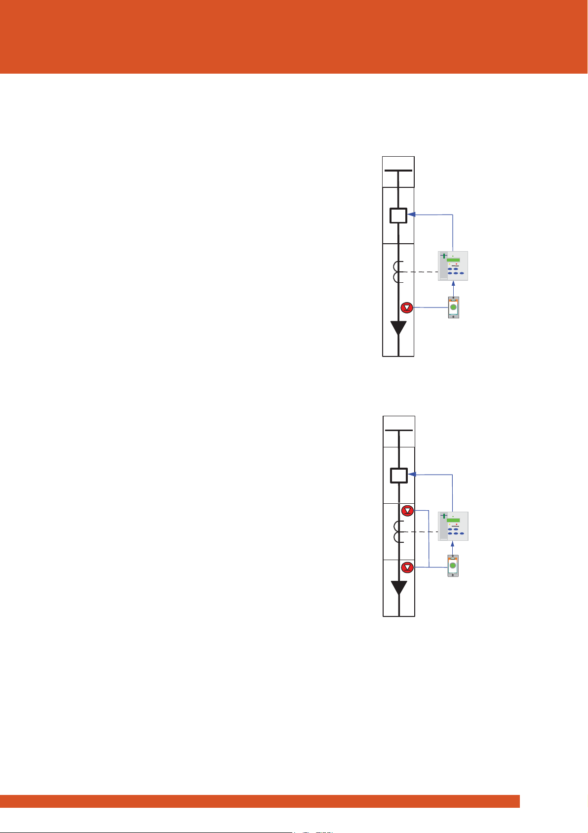
Switchgear ARC Flash Protection
Risk of arc fault damage exists at the CB cable termination and in
the CB chamber itself. The CB cable termination is particularly at
risk to ingress of moisture and rodent damage.
One, two or three arc sensors may be connected to the 1S20 Arc
Fault Monitors as depicted in the single line application diagrams
at right.
Figures 4 and 5 show the trip signals being used to trip the feeder
circuit breaker in the event of an arc fault occurring at any sensor
provided the overcurrent relay starter contact is picked up. In
these applications the overcurrent check stage is optional as the
consequence of a single feeder outage is less than the loss of an
entire BUS.
Figure 7 shows an application where a single 1S20 is applied for
the protection of the Cable box, CT chamber and CB chamber
using three sensors. In this configuration one arc trip output is
used to trip the feeder circuit breaker in the event of an arc fault
in the cable box / CT chamber. The second trip output is set for
independent operation to trip the BUS breaker (BUS overcurrent
check not shown), in the event of an arc fault in the CB chamber.
Existing Switchgear Applications
The existing overcurrent relay protecting the feeder will normally
provide an independent output contact associated with the start
current setting of the relay. That is an output contact that will
close when a phase or earth fault current is detected above the
threshold which starts the internal relay timers. This starter
element should be set for instantaneous operation so that it will
pick up in the o
rder of 15ms.
An Arc Fault Monitor relay 1S20 is installed on the switchgear
panel adjacent to the protection relay. The 1S20 is specifically
designed for simple retrofit to existing panels or DIN rail mounted
within the instrument chamber.
1S30 optical arc sensors are fitted in the cable termination box
and CT chamber as depicted in figure 5.
The overcurrent relay starter contact may optionally be wired in
series with the arc fault detection trip output contact as depicted
in figure 6. The resulting “AND” function trip output is wired to
trip the breaker in ~15ms in the event that an arc fault is detected
while the overcurrent start element is picked up.
Figure: 4:
Single point sensor -
Cable box
Figure: 5:
Two point sensors - Cable box and
CT chamber
1S30
1S20
50/51
1S30
1S30
1S20
50/51
www.rmspl.com.au
rms
5
Applications
1S20
New Switchgear A
pplications
For new switchgear installations a modern numeric feeder
protection relay is likely to be employed which will have numerous
programming and configuration options.
The basic concept is the same as for the existing switchgear
application described above except that the additional features
and flexibility of modern feeder protection relay allows improved
system integration.
This may be achieved by using the second arc trip output contact
to interface to a programmable status input on the feeder
protection relay. Depending on the model of protection relay
being used this input may be programmed to provide an alarm
message on the HMI, time stamped event record available via its
communications link.
Where this level of system integration is employed the 1S20 does
not need to be mounted on the front panel as the alarm
indications are available on the feeder relay. Remote reset of the
1S20 LED is achieved by momentary interruption of the power
supply using a SCADA controlled series contact. The DIN rail
mounting option is a convenient alternative in this situation.
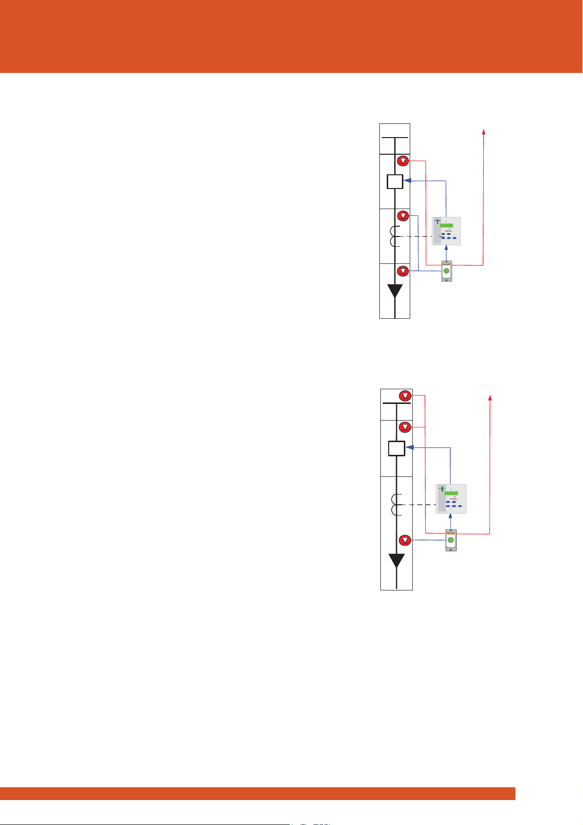
Combined Bus Bar & Switchgear Arc Protection
Figure 7 shows an application where a single 1S20 is applied for
the protection of the Cable box & CT chamber plus the CB chamber
& B
US chamber using three sensors.
In this configuration one arc trip output is used to trip the feeder
circuit breaker in the event of an arc fault in the cable box / CT
chamber. The second trip output is set for independent operation
to trip the BUS breaker
(BUS overcurrent check stage not shown),
in the event of an arc fault in the CB chamber or BUS chamber.
Figure: 7:
One arc sensor - Cable box / CT chamber
Independent trip to CB
Two arc sensors - CB chamber & BUS chamber
Independent trip to BUS breaker
(BUS overcurrent check stage not shown)
Figure: 6:
Two point sensors in zone 1 - Cable box and
CT chamber
One point
sensor in zone 2 for CB chamber
1S20
1S30
1S30
1S30
50/51
Trip BU
S
C
B
(
s
)
1S20
1S30
1S30
1S30
50/51
Trip BU
S
C
B
(
s
)
1S20
1S30
1S30
1S30
50/51
Trip BU
S
C
B
(
s
)
1S20
1S30
1S30
1S30
50/51
Trip BU
S
C
B
(
s
)

www.rmspl.com.au
rms
6
Applications
1S20
Figure: 8: Bus bar arc protection single line schematic
Bus Bar Arc Protection
Figure 8 depicts how the 1S20 may also be applied for the
protection of bus bars. The number of sensors in the bus
chamber is dictated by the switchgear design and the length of
switchboard.
In most indoor metal clad switchgear the bus bar chamber is a
continuous chamber between panels only broken into
segregated sections at a bus section breaker & as such the
strategic placement of one or two arc sensors in each bus bar
chamber run is normally adequate.
Some indoor metal clad switchgear may segregate the bus
chamber of each panel from the next via insulated bus chamber
side barriers per panel, if this is the case then each bus chamber
per panel would need to be monitored by at least one arc
sensor.
In large enclosures the arc sensors should be placed at
approximately 5m intervals.
1S30 Shielded Cables
Shielded cables are recommended when the length of the 1S30
cable con
nections exceed 6m.
1S20
1S30 1S30
50/51
50/51 50/51
www.rmspl.com.au
rms
7
Configuration
1S20
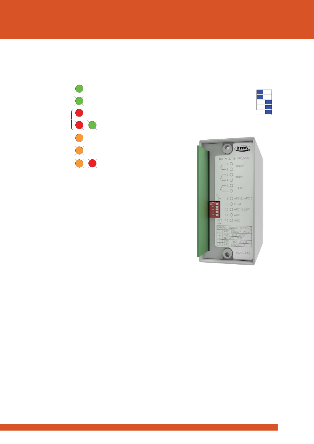
Operation Indicator
A single tri colour LED is integrated into the front panel reset push
button to provide the following status indications:
Figure 9: Front panel LED indication
Configuration Switch Settings
The internal wiring label identifies the position of the following
switch functions:
Switch 1:
Arc sensor 2
ON - Arc Sensor 2 fitted
OFF - Arc Sensor 2 not fitted
Switch 2:
Arc fault trip indication LED reset
ON - Latching until manually reset
OFF - Automatic self-
reset (Extinguish) after 4
hours Will also reset conta
cts set for
latching function
Switch 3:
Independent arc trip output contacts
ON -
Arc Sensor 1 activates trip output contact 1
& Arc sensor 2 or 3 activates trip output
contact 2
OFF -
Arc Sensor 1, 2 or 3 activate both trip
outputs
Switch 4:
Arc fault trip output contact reset
ON - Latching – Reset with trip LED
OFF - Self-reset after 2s
Switch 5:
Arc sensor 3
ON - Arc Sensor 3 fitted
OFF - Arc Sensor 3 not fitted
Function Configuration
The configuration switches are accessible to the user by first
unplugging the electronic module from
the terminal base as
shown in
figures 10 and 11.
Figure 10
: Front panel mode selector switch
Figure 11:
1S20 rear view showing configuration switches
WARNING:
Removal of the 1S20 from the base may
expose live terminals
Arc Sensor
Circuit Supervision
The 1S30 Arc Sensor is the heart of the system & supervision of
circuit continuity is critical for correct operation. To monitor the
integrity of the wiring between the 1S30 arc sensor & 1S20 Arc
Monitor, a continuous 2mA supervision current flows between
the units. The 1S20 alarm contact will drop out after a 1s time
delay if it fails to detect this current.
Where a fault is detected on the Arc Sensor 1 circuit the front
panel LED will give a solid orange indication.
Where a fault is detected on Arc Sensor 2 or 3 circuits the front
panel LED will give a flashing orange indication.
Where a fault is detected on Arc Sensor 1 & 2 or 1& 3 circuits the
front panel LED will give a solid orange indication.
Solid red for 2s followed by:
Alternate red & green until reset.
Green solid
Orange flashing
Orange solid
Alternate orange & red.
System healthy
1S30Arc Sensor 2 or 3 service
1S30Arc Sensor 1 service
1S30Arc Sensor continuous pick up
Flash green 3 times1S30 Power up test OK
Arc fault trip
ON
ON
ON
ON
ON
OFF
OFF
OFF
OFF
OFF
1: ARC SENSOR 2
2: LATCHING TRIP LED
3: INDEPENDENTARC TRIP
4: LATCHING TRIP CONTACTS
5: ARC SENSOR 3
www.rmspl.com.au
rms
8
Technical Data
1S20
Auxiliary Supply
Low Range Version
Order Code F
Nominal dc Voltage Supply
24 / 32 / 48
Standards Compliant Range
(Shown on relay
rating plate
)
19
-85V dc
19
-65V ac
Absolute Range
18-100V dc
15-75V ac
Mid-Range Version
Order Code G
Nominal dc Voltage Supplies
110 / 125
Standards Compliant Range
(Shown on relay
rating plate
)
45
-165V dc
38
-150V ac
Absolute Range
36-200V dc
30-175V ac
High Range Version
Order Code H
Nominal dc Voltage Supplies
220 / 240 / 250
Standards Compliant Range
(Shown on relay
rating plate
)
125
-250V dc
94
-240V ac
Absolute Range
100
-300V dc
75
-275V ac
Allowable breaks/dips in
supply (Collapse to zero)
As per IEC60255
-26 *7.2.11
Burden - Quiescent
8W at 110V dc
Burden - Maximum
15W at 110V dc
Output
Contacts
Operating Voltage
Voltage free
Operating Mode
Self-reset
Trip Contact Operate Time
<10ms (Flash to contact closure)
Reset Time
2s (Self reset setting)
Making Capacity
Carry Continuously
5A ac or dc
Make and Carry
L/R
≤ 40ms and ≤ 300V
20A ac or dc for 0.5s
30A ac or dc for 0.2s
Breaking Capacity
L/R ≤ 40ms and ≤ 300V
AC Resistive
1,250VA
AC Inductive
250VA at p.f. ≤ 0.4
DC Resistive
75W
DC Inductive
30W at L/R ≤ 40ms
50W at L/R ≤ 10ms
Minimum Load
100mA ≥12V
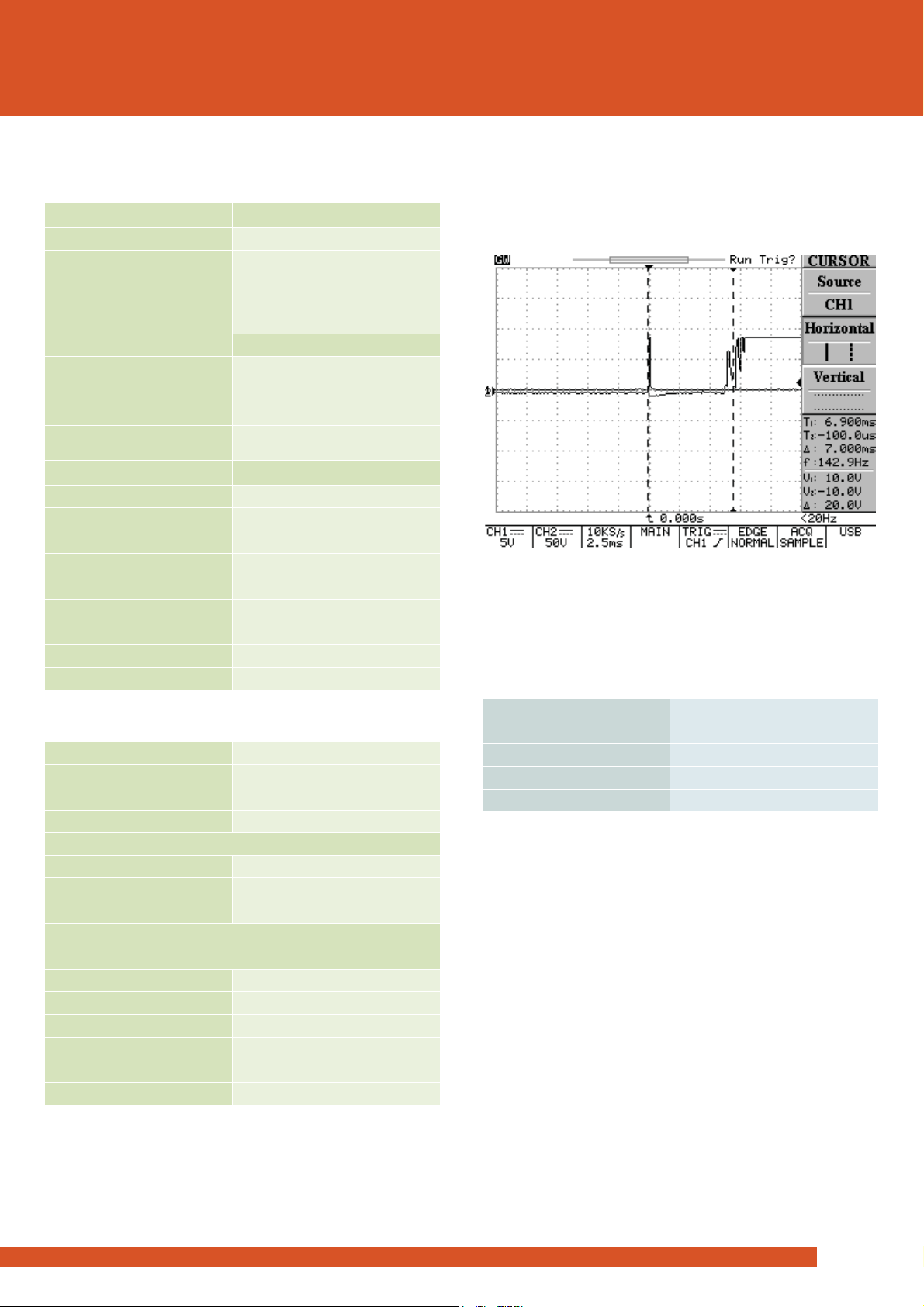
Operating Time
Arc fault trip contacts guaranteed to pick up in less than 10ms
including bounce. Typical operate time is 7ms.
CRO trace showing nominal operation time of the trip contacts at
7ms. First contact touch at 6.25ms and fully closed by 7.25ms.
Operation in <10ms is considered acceptable as current check
relay operate time is ~15ms.
Arc Fault Point Sensor Inputs
Number
2 or 3
Type
1S30 point sensors
Connection
Electrical termination
Zones
1 or 2
Supervision duration
Continuous
Minimum Arc Duration
The minimum arc “flash” duration required to guarantee
operation of the output contacts is
2.2ms.
Trip Contact Reset Time
Once operated the trip output contacts reset as per the
configuration switch 4 setting
.
Manual Reset
Press
front button or interrupt power supply to reset LED’s.
Case
ZA12 flush or DIN rail mount type
12 M4 screw terminals
Plug in module to facilitate easy wiring & fast changeover

www.rmspl.com.au
rms
9
Compliance Data
1S20
ELECTRICAL ENVIRONMENT
AC and DC Voltage Dips
Standard
IEC 60255-26, #7.2.11
Test Level
Test specification
Dip to 0% of residual voltage
Acceptance criterion A
DC: 20 ms
AC: 1 cycle 50/60 Hz
Dip to 40% of residual voltage
Acceptance criterion C
DC: 200 ms
AC: 10/12 cycles 50/60 Hz
Dip to 70% of residual voltage
Acceptance criterion C
DC: 500 ms
AC: 25/30 cycles 50/60 Hz
AC and DC Voltage Interruptions
Standard
IEC 60255-26, #7.2.11
Acceptance criterion C
Test Level
Test specification
Drop to 0% of residual voltage
DC: 5 s
AC: 250/300 cycles 50/60 Hz
AC Component in DC (Ripple)
Standard
IEC 60255-26, #7.2.12
Acceptance criterion A
Test Level
Test specification
15% of rated DC value
100/120 Hz, Sinusoidal
Gradual Shut
-down/Start-
up (DC Power Supply)
Standard
IEC 60255-26, #7.2.13
Acceptance criterion C
Test Identification
Test specification
Shut-down ramp
60 s
Power off
5 min
Start-up ramp
60 s
Clearances and Creepage Distances
Standard
IEC 60255-26, #10.6.3
Test Identification
Test specification
Pollution degree
2
Overvoltage category
III
Rated insulation voltage
300 V rms or dc
Clearances and Creepage
Compliance
CAD drawings assessment
Safety
-related Electrical Tests
Standard
IEC 60255-27, #10.6.4
Test Identification
Test specification
Between Independent Circuits
5 kV 1.2/50 μs 0.5 J
3 pulses of each polarity
2.0 kV ac rms for 1 minute
Any Terminal and Earth
5 kV 1.2/50 μs 0.5 J
3 pulses of each polarity
2.0 kV ac rms for 1 minute
Across Normally Open Contacts
1 kV ac rms for 1 min
Electrical Environment and Flammability
Standard
IEC 60255-27, #10.6.5
Test Identification
Test specification
Single-fault condition
Assessment
Maximum temperature of
accessible
parts at ambient
temperature +40°C
Metal parts: < 70°C
Non
-metallic parts: < 80°C
Flammability of insulating
materials, components and fire enc
Assessment
Reverse Polarity and Slow Ramp Test
Standard
IEC 60255-27, #10.6.6
Test Identification
Test specification
Maximum voltage dc
V start-up + 20%
Minimum voltage dc
V shutdown - 20%
Ramp down/up gradient
1 V/min

www.rmspl.com.au
rms
10
Compliance Data
1S20
ATMOSPHERIC
ENVIRONMENT
Temperature
Standard
IEC 60068-2-1, IEC 60068-2-2
Test Identification
Test specification
Auxiliary power
Supply voltage
Operating Range
-10 to +55°C
Min and Max
Storage Range
-25 to +70°C
Non-energized
Test duration
16 h at top and bottom temperatures
Damp Heat (Humidity)
Standard
IEC 680068-2-78
Test Identification
Test specification
Operating Range
40°C and 93% RH non condensing
Test duration
16 h
IP Rating
Standard
IEC 60529
Test Identification
Test specification
Installed
IP4x
MECHANICAL ENVIRONMENT
Vibration
- Sinusoidal
Standard
IEC 60255-21-1 Class 1
Test Identification
Test specification
Variation
Vibration Response
in each of 3 axes
0.035 mm/0.5 gn peak
1 sweep cycle 10-150 Hz
No Mal
-Op
Vibration Endurance
in each of 3 axes
1.0 gn peak
20 sweep cycles
10-150 Hz
Non
-
energized
Shock and Bump
Standard
IEC 60255-21-2 Class 1
Test Identification
Test specification
Variation
Shock Response
in each of 3 axes
5 gn, 11 ms, 3 pulses
in each direction
No Mal
-Op
Shock Withstand
in each of 3 axes
15 gn, 11 ms, 3 pulses
in each direction
Non-
energized
Bump Test
in each of 3 axes
10 gn, 16 ms, 1,000
bumps in each direction
Non-
energized
Seismic
Standard
IEC 60255-21-3 Class 1
Test Identification
Test specification
Variation
Seismic Response
Horizontal, on each axis
3.5 mm/1.0 gn,
1 sweep cycle 1-35Hz
No Mal
-Op
Seismic Response
Vertical
1.5 mm/0.5 gn,
1 sweep cycle 1-35Hz
No Mal
-Op

www.rmspl.com.au
rms
11
Compliance Data
1S20
ELECTROMAGNETIC COMPATIBILITY (EMC)
IMMUNITY
Electrostatic Discharge (ESD)
Standard
IEC 60255-26, #7.2.3, Acceptance criterion B
Port
Enclosure
Test Identification
Test specification
Variation
Air Discharge
8 kV
No Mal-Op
Radiated Electromagnetic Field
Standard
IEC 60255-26, #7.2.4, Acceptance criterion A
Port
Enclosure
Test Identification
Test specification
Variation
Frequency sweep
10 V rms, 80 to 1000 MHz
1400 to 2700 MHz
No Mal
-Op
Spot frequencies
10 V rms, 80, 160, 380,
450, 900, 1850 & 2150 MHz
No Mal
-Op
Fast Transients (EFT)
Standard
IEC 60255-26, #7.2.5, Acceptance criterion B
Port
Auxiliary power supply, Input and Output,
Functional Earth
Test level
Test specification
Variation
Zone A
4 kV peak, 5/50 ns, 5 kHz
No Mal-Op
Slow Damped Oscillatory Wave (HFD)
Standard
IEC 60255-26, #7.2.6, Acceptance criterion B
Port
Auxiliary power supply, Input and Output
Test Identification
Test specification
Variation
Common Mode
1 MHz 2.5 kV peak
No Mal-Op
Differential Mode
1 MHz 1.0 kV peak
No Mal-Op
Surge
Standard
IEC 60255-26, #7.2.7, Acceptance criterion B
Port
Auxiliary power supply, Input and Output
Test Identification
Test specification
Variation
Line-to-earth
4 kV peak
No Mal-Op
Line-to-line
2 kV peak
No Mal-Op
Conducted Disturbance Induced by RF Fields
Standard
IEC 60255-26, #7.2.8, Acceptance criterion A
Port
Auxiliary power supply, Input and Output,
Functional Earth
Test Identification
Test specification
Variation
Frequency sweep
10 V rms, 0.15 to 80 MHz
No Mal-Op
Spot frequencies
10 V rms, 27 & 68 MHz
No Mal-Op
Power Frequency Magnetic Field
Standard
IEC 60255-26, #7.2.10
Port
Enclosure only
Test Identification
Test specification
Continuous ≥ 60 s
30 A/m - Acceptance criterion A
Short time 1 s to 3 s
300 A/m - Acceptance criterion B
EMISSION
Emission Enclosure
Standard
IEC 60255-26, #5.1
Test Identification
Frequency range
Limits, dB (μV/m)
Radiated emission
<1 GHz
30
- 230 MHz
40, quasi peak at 10 m
50, quasi peak at 3 m
230
-
1000 MHz
47, quasi peak at 10 m
57, quasi peak at 3 m
Radiated emission
>1 GHz
1
– 3 GHz
56, average
76, peak at 3 m
3
– 6 GHz
60, average
80, peak at 3 m
Emission Auxiliary Power Supply Port
Standard
IEC 60255-26, #5.2
Test Identification
Frequency range
Limits, dB (μV/m)
Conducted emission
0.15
–
0.50 MHz
79, quasi peak
66, average
0.5
- 30 MHz
73, quasi peak
60, average
www.rmspl.com.au
rms
12
Wiring
1S20
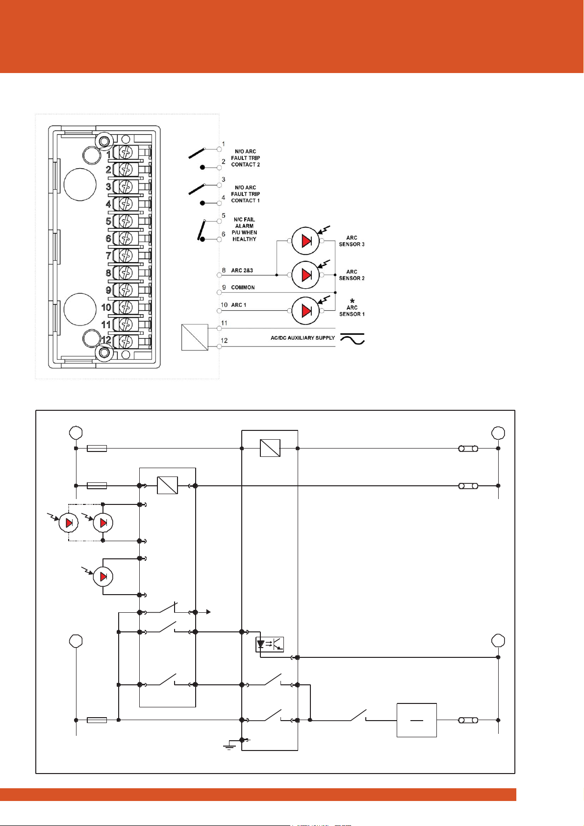
1S20 Wiring Diagrams
Figure 12: 1S20 Socket Terminal Layout viewed from the front when un-
plugged from the main housing.
Note: * Always wire Arc Sensor 1. Arc Sensors 2 & 3 are optional
1S20 application diagram - Circuits shown in de-energised condition
12
8
10
9
9
5
1
3
11
6
2
4
Vx
+
+
-
-
Fail
alarm
Arc 1
(Must b ewire d)
Arc3 Arc2
Arc fault trip alarm signal to
protection relay status input for comms.
I>start
Control
Protection
1S20
50/51
Overcurrent
relay
Arc fault
relay
I>
CBAux Switch Trip Coil
52
T
52 - a
www.rmspl.com.au
rms
13
1S20
Mounting and Dimensions
Mounting Options
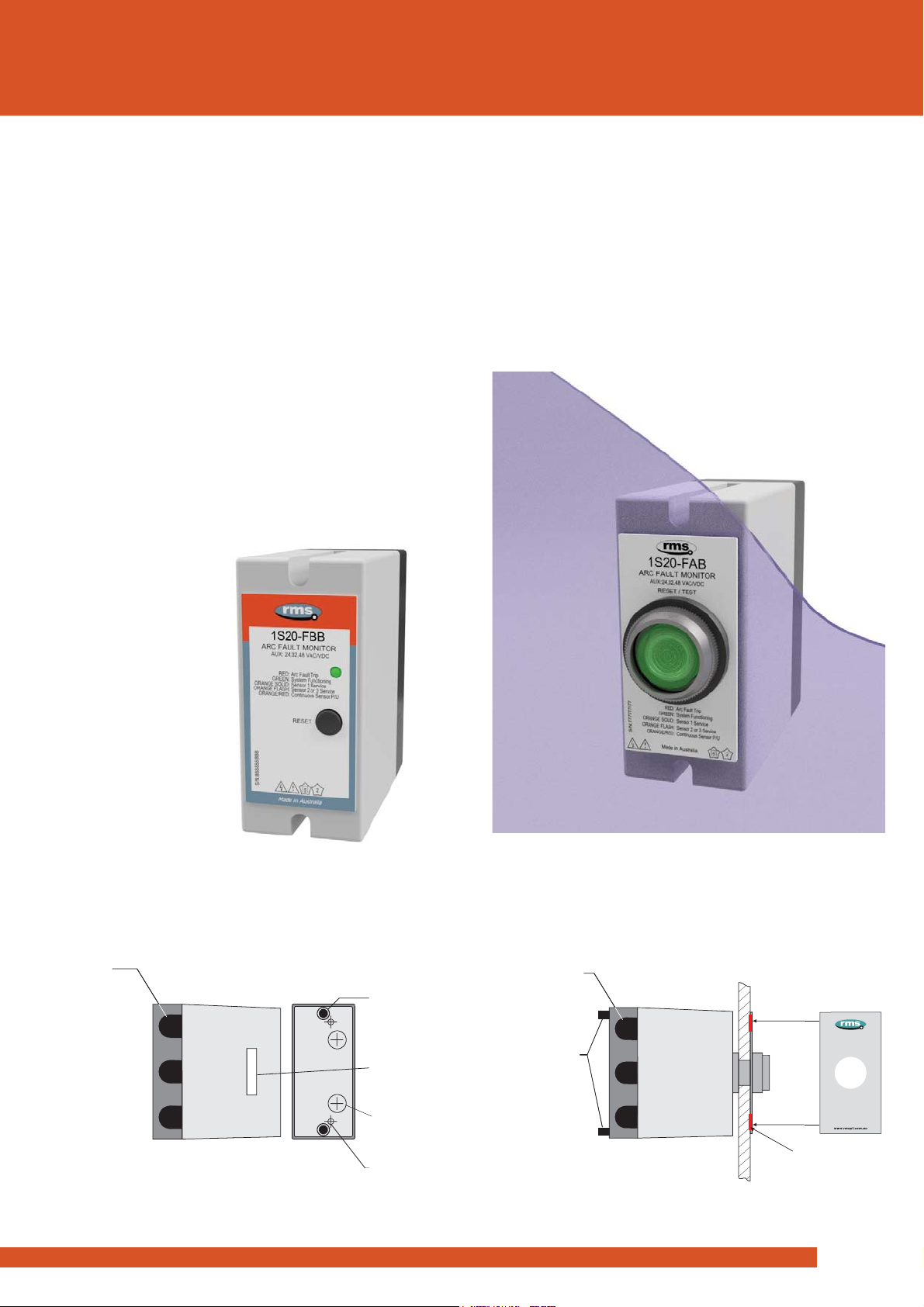
The 1S20 is available in two versions:
1. A surface mount version which has a separate reset button
& LED indicator on the front panel. The advantage of this
version is the lower cost &
where front panel space in
limited.
2. A panel mount version which has a combined reset button &
LED indication. The advantage of this version is that it can be
either panel or surface mounted.
Surface Mount Version
This version is suitable for location in
the rear of a cubicle. It may
be surface mounted as shown in figures 13, 14 and 18. It may
also be DIN rail mounting when the optional 290407157 DIN Rail
Mounting Kit is fitted. Refer figures 21 and 22.
Figure 13: 1S20 surface mount versi
on front panel
Figure 14
: Surface mount version side view
Panel
Mount Version
This version is suitable for mounting on the front panel of a
cubicle or door. This is achieved using a 31mm diameter hole in
the panel adjacent to the protection relay as depicted in figures
15, 16 and 17.
This version may also be surface mounted by reversing the
terminal block retaining screws. It may also be DIN rail mounting
when the optional 290407157 DIN Rail Mounting Kit is fitted.
Refer figures 19 and 22.
Figure 15: 1S20 through hole panel mount version
Figure 16
: Panel mount version side view
SERIAL NO. &
RATING LABEL
ON MODULE SIDE
FOR PANEL
MOUNT VERSION
REMOVE FOR
REAR CABLE
ENTRY OPTION
REMOVE FOR
TWO M4 OR 4BA
MOUNTING SCREWS
TOP & BOTTOM REAR
TERMINAL BLOCK
RETAINING SCREWS
S
LIDE
O
UT
C
ABLE
ENTRY POINTS
3 ON ONE SIDE
1 AT EACH END
1S20K2 (CAB)
AUX:36-150V DC S/N:123456
Use double sided tape supplied
Top & bottom positions
RELAY PANEL
3mm THICK
MAXIMIUM
FRONT PANEL
LABEL
(Supplied with module)
SLIDE OUT CABLE
ENTRY POINTS
3 ON ONE SIDE
1 AT EACH END
TOP & BOTTOM REAR
TERMINAL BLOCK
RETAINING SCREWS
THESE MAY BE
UNSCREWED &
REVERSED TO FIT
FROM THE FRONT OF
THE 1S20 MODULE TO
ALLOW SURFACE
MOUNTING
RETENTION
SHROUD
1S20 Arc Fault Monitor
RESET / TEST
System Functioning
Arc Fault Trip
Sensor 1 Service
Sensor 2 or 3 Service
Continuous Sensor P/U
DC Supply Fail
GREEN:
RED:
ORANGE SOLID:
ORANGE FLASH:
ORANGE / RED:
NONE:

www.rmspl.com.au
rms
14
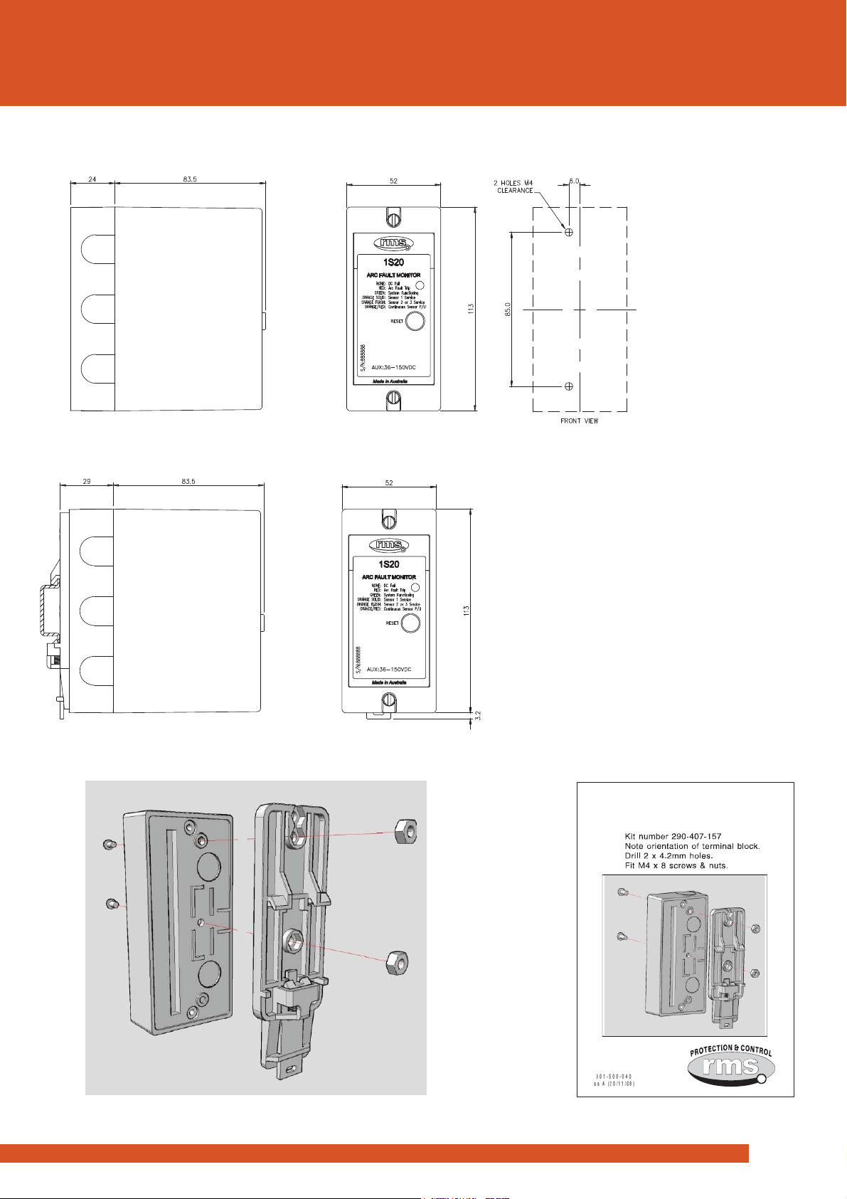
1S20
Mounting and Dimensions
Panel Mount Version
Figure 17: Panel mounting cut out detail
Figure 18: Surface mounting
detail
Figure 19: DIN rail mounting detail
1S20
15
Mounting and Dimensions
rms
Surface Mount Version
Figure 20: Surface mounting detail
Figure 21: DIN rail mounting detail
Figure 22: DIN rail clip fitting detail –
Specify DIN Rail Mounting Kit P/N 290407157
DIN RAIL
MOUNTING KIT

16
rms
Order Codes
1S20
1S20 -
Auxiliary Supply
F
19-85 V DC or 19-65V AC
G
45-165 V DC or 38-150V AC
H
125-250V DC or 95-240 V AC
Mounting
A
Panel mount or surface mount
B
Surface mount only
C
As per A with DIN rail kit supplied
D
As per B with DIN rail kit supplied
Sensors
A
Two arc sensor inputs (Default)
B
Three arc sensor inputs
1S20 Relay
Order Codes
Auxiliary Supply Order Code Change Guide
Old
Applied Auxiliary Voltage
New
1S20-Axx
1S20-
Axx *
1S20-
Axx *
24/32/48V DC
110V AC
230/240/250V AC
1S20-Fxx
1S20-Gxx #
1S20-Hxx
#
1S20-Cxx
110/125V DC
1S20-Gxx
1S20-Dxx
220/240/250V DC
1S20-Hxx
1S20-Exx *
110V AC
1S20-Gxx #
* When used with AC/DC power supply adaptor
# Direct connection to AC auxiliary supply

Due to RMS continuous product improvement policy this information is subject to change without notice. 1S30/Issue I/03/05/16 - 1/5
Features
Compact rugged design
One or two optical detectors
High speed arc detection
Heavy duty 6m termination
cable
Optional 20m & screened
cables
Simple flush panel mounting
outside or inside switchgear
compartment
Integrated sensor circuit
supervision
Very low sensitivity to ambient
light levels to avoid nuisance
tripping even in direct sunlight
Sealed module for harsh
environments
Optional metal reinforced
mounting shield
Application
Arc fault protection is a relatively new
technique employed for the fast clearance
of arcing faults on BUS bars & within
metal clad switchgear & associated cable
boxes. The arc is detected using an
optical sensor & the signal input to a
protection device which also monitors the
load current on the system. A trip signal
can be achieved in less than 10ms using
arc detection.
RMS manufactures a protection class arc
fault optical sensor & monitoring system
suitable for both low & medium voltage
switchgear and BUS bar applications.
1S20 3 sensor, 2 zone Arc Fault Monitor
1S25 8 sensor, 4 zone Arc Fault Monitor
1S26 1S25 with integrated current check
1S30 Optical Arc Fault Sensor
While the high intensity flash caused by
an electrical arc will be reflected within the
metal clad switchgear, it is recommended
that one or more sensors be mounted in
each enclosed switchgear compartment.
For BUS bar protection applications
multiple sensors are required to achieve
adequate coverage along the length of the
BUS. A sensor version with two optical
detectors “looking” in opposite directions
is available for this purpose (Refer figure 3
for generic layout).
Technical Bulletin 1S3
0
Optical Arc Fault Sensor
1S30 Arc Fault Sensors
Through panel mounting detector Front panel view of dual detector
View depicted at left version depicted at right
Description Made in Australia
The 1S30 is an optical sensor that responds to the flash of light emitted during the
incidence of an arcing fault. Onset of the light flash & detection by the 1S30 occurs in a
few ms.
Each arc fault sensor consists of one or two silicon PIN photo diode light detectors
mounted on a circuit board together with the associated detection circuit (Figures 1 & 2).
The detector monitors a wide space angle. A broad spectral response in the visible region
is provided as depicted in figure 5.
Sensitivity of the arc sensor has been set to a low level to reduce the possibility of mal
operation under high ambient lighting conditions. This is made possible due the high
intensity of light emitted under arc fault conditions. Additional security can be incorporated
by way of a current check stage as described in the 1S20 Arc Fault Monitor Technical
Bulletin.
In stand by mode the 1S30 sensor presents a high resistance to the 12V DC control signal
provided by the 1S20, 1S25 or 1S26 Arc Fault Monitors. This allows a small circulating
current to flow for continuous supervision of the 1S30 connection circuit. When an arc is
detected, the resistance presented by the 1S30 drops to a level where the current flow
increases to approximately 20mA. This increased current flow is instantaneously detected
by the Arc Fault Monitor & its trip output contacts closed. Refer to the 1S20 Arc Fault
Monitor Technical Bulletin for further details.

Due to RMS continuous product improvement policy this information is subject to change without notice. 1S30/Issue I/03/05/16 - 2/5
SINGLE DETECTOR PACKAGE
Figure 1 depicts the 1S30 with a single optical detector. Note the
window where the active part of the detector is positioned to. This
permits convenient mounting on the outside of the panel with the
detector window protruding a hole in the panel.
Figure 1:
DUAL DETECTOR PACKAGE
Figure 2 depicts the 1S30 with dual optical detectors. The two
optical detectors face in opposite directions to provide arc
detection coverage in both directions. This version is particularly
useful when mounted in a BUS chamber or barrier between
adjacent switchgear chambers. The main benefits are reduced
cost compared to two separate sensors & use of only one input
channel on the 1S20 Arc Fault Monitor.
Figure 2:
DETECTOR RANGE
A detection range along the 100% relative sensitivity curve
shown in figure 3 is approximately 3m. Single detector versions
therefore need to be placed at a maximum spacing of 5-6m. The
dual detector versions may be placed at a maximum spacing of
5-6m to provide adequate detection overlap. In switchgear the
light caused by the arc is reflected from the walls & therefore, the
mounting of the sensor is not critical.
While the high intensity flash caused by an electrical arc will be
reflected within the metal clad switchgear, it is recommended that
one or more sensors be mounted in each enclosed switchgear
compartment.
Figure 3:
Detector Characteristics
OPTICAL SENSITIVITY
~10,000 Lux* for white light at normal incidence to the detector
window(s) as depicted in figure 4:
Rear
Detector
1S30 [B]
models only
Light
Source
Front
Detector
1S30 [A] & [B]
models
Light
Source
Figure 4:
For the 1S30-A single detector version the front detector only is
fitted. In this configuration the 1S30-A will be insensitive to white
light incident on the rear surface of the case up to a level of
200,000 Lux.
As the illuminace of diffuse ambient sunlight falls in the range
5,000 to 10,000 Lux, this will not normally be sufficient to trigger
the 1S30 sensor. The luminous intensity from the sun at noon at
the equator however is ~100,000 Lux which will be sufficient to
trigger the 1S30 sensor so measures should be made to avoid
this situation.
Direct sunlight incident on the rear of the 1S30-A model sensor
will not cause it to pick up. This attribute provides a significant
safety margin to avoid nuisance tripping when the option of
mounting the sensor externally on switchgear as depicted in
figure 6 is employed.
DETECTOR DIRECTIONAL CHARACTERISTICS
Detector sensitivity falls to ~40% of the nominal level at
inclination angles up to 70 degrees from the normal for white
light.
DETECTOR SPECTRAL RESPONSE
50%
60%
70%
80%
90%
100%
600 700 800 900 1,000 1,100 1,200
Wavlength (nm)
Relative Sensitivity
Figure 5:
Arc detector spectral response
* Due to the relatively high sensitivity of the detector to IR
wavelengths the type of light source employed for sensitivity
testing will have a major effect on the results obtained.
Sensitivity testing should therefore be conducted using a 50-75W
halogen lamp with an integrated aluminum reflector.

Due to RMS continuous product improvement policy this information is subject to change without notice. 1S30/Issue I/03/05/16 - 3/5
FLUSH PANEL MOUNTING
The 1S30 is suitable for flush panel mounting in a number of
configurations.
Figure 6:
1S30 shown mounted on the outside of a switchgear panel
Detector oriented to ‘look’ through a hole into the switchgear
Figure 7:
1S30 shown mounted on the inside of a switchgear panel
Detector oriented to ‘look’ out into the switchgear compartment
FLUSH MOUNT REINFORCING PLATE
When mounting the 1S30 on the outside of a switchgear cubicle
as depicted in figure 6, the hole required in the panel may
degrade the short circuit rating. If this is considered to be an
issue then a reinforcing plate may be fitted over the 1S30 as
depicted below.
Figure 8:
Flush mount reinforcing plate
1.2mm zinc plated mild steel
Mounting
Options
DUAL DETECTOR VERSION
The dual detector version can be panel mounted to monitor two
adjacent switchgear compartments simultaneously. This feature
can be used to reduce the total cost for sensors or to increase
the monitoring coverage for each 1S20 Arc Fault Monitor unit.
Figure 9:
1S30 shown mounted on the inside of a switchgear panel
This configuration combines the functions described in
Figures 6 & 7 with the application of a single
dual detector arc fault sensor
PANEL MOUNT CUT OUT DETAIL
Figure 10:
Flush mounting detail
RIGHT ANGLE MOUNTING OFF A SURFACE
A right angle mounting bracket may be fabricated using the panel
cut out detail in figure 10. Single & dual detector models may be
mounted in this manner as depicted below.
Figure 11:
Right angle mounting off a surface
Mount off floor or walls within switchgear / BUS bar chamber
Switchgear
panel
2 x M4
self threading
mounting screws
(Supplied)
Sealed cable
stress relief
Optical detector
protruding through
hole in panel
2 x M4
self threading
mounting screws
(Supplied)
Optical detector
facing away
from panel
2 x M4
self threading
mounting screws
(Supplied)
Flush mount
reinforcing
plate
Internal partition
between switchgear
compartments
Optical detector
protruding through
compartment divider
into adjacent
switchgear chamber
Optical detector
window facing away
from compartment
divider
Hole in panel
to allow detector
to ‘look’ into
switchgear
chamber
Right angle
mounting
bracket
Optical detector
window facing away
from right angle
mounting bracket
Single
optical detector Dual
optical detector
Due to RMS continuous product improvement policy this information is subject to change without notice. 1S30/Issue I/03/05/16 - 4/5
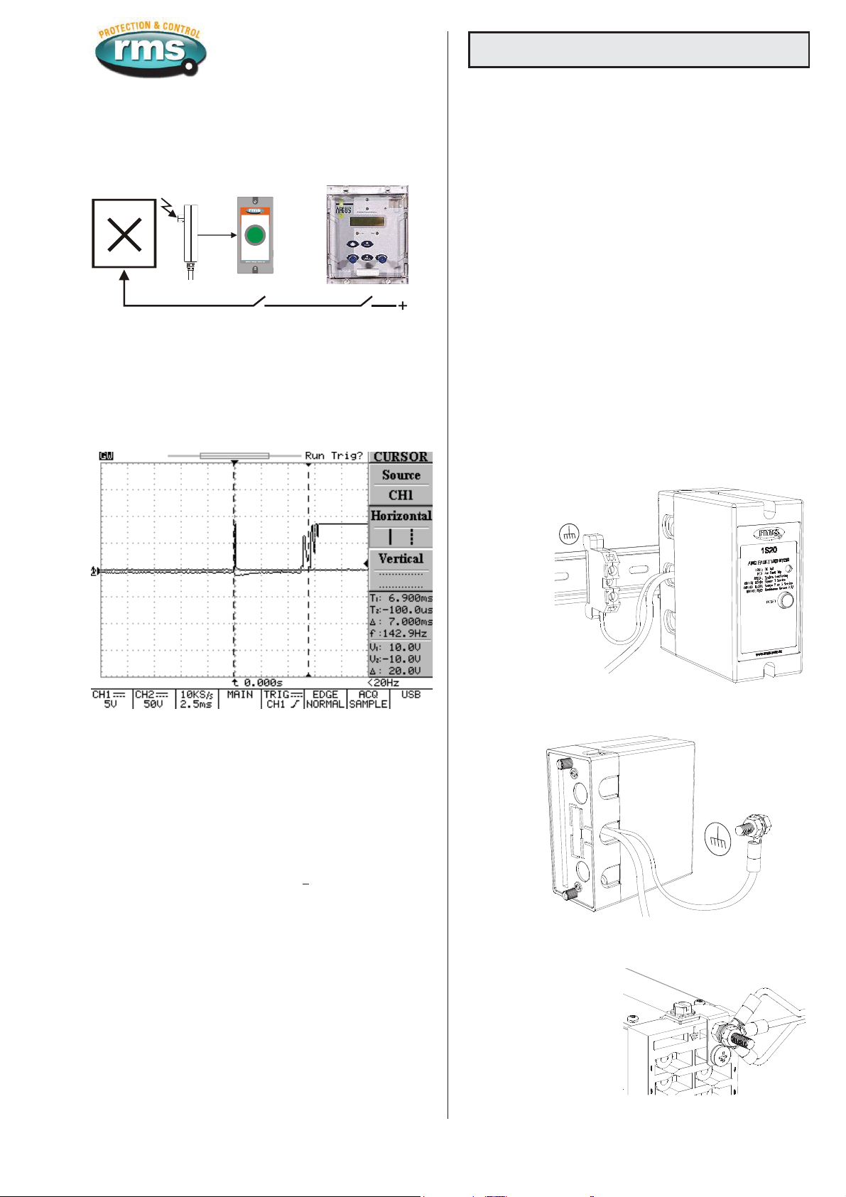
ARC FAULT PROTECTION SCHEME
Refer to the 1S20 Technical Bulletin for further details.
Type:1S20K1 [C] Vx: 48V DC
Serial No: 126578
1S20 Arc Fault Mo nitor
ARC FAULT TRIP INITIATE
CB ARC FAULT
MONITORSENSOR
OVER-CURRENT RELAY
3 Pole OC + EF
RESET / TEST
System Functioning
Arc Fault Trip
System Service
DC Fail
GREEN:
RED:
ORANGE:
DARK:
Figure 12:
Key components required to implement an Arc Fault Protection
scheme with an overcurrent check stage
to enhance system security
ARC PROTECTION SCHEME OPERATE TIME
The total time required for detection of the arc flash to closure of
the 1S20 Arc Fault Monitor trip contacts is less than 10ms
including bounce. Typical operate time is 7 to 8ms.
Figure 13:
CRO trace showing nominal operation time of the trip contacts at
7ms. First contact touch at 6.25ms and fully closed by 7.25ms.
Operation in <10ms is considered acceptable as current check
relay operate time is ~15ms.
MINIMUM ARC DURATION
The minimum arc “flash” duration required to guarantee operation
of the Arc Fault Monitors output contacts is 1.25ms.
AUXILIARY SUPPLY
Voltage from 1S20 Arc Fault Monitor: 12V DC
Power consumption: <2.5mA
CASING
Rugged moulded construction to IP51.
TEMPERATURE RANGE
Operating: -5 to +55oC
Storage: -25 to +75oC
Technical Data
SENSOR CONNECTIONS
The 1S30 is supplied with a 6m two core connection cable as
standard. Two core multi strand wire (2x16/0.2mm), is supplied
stripped & pre tinned at the 1S20 connection end. The standard
6m cable may be cut down to the desired length & crimp ring lugs
fitted for termination to the 1S20, 1S25 or 1S26 Arc Fault
Monitors.
The 1S30 connections are not polarity sensitive. Reversal of the
wires on the arc monitor terminals has no effect on the
performance of the 1S30 or arc detection system.
The cable is factory fitted to the 1S30 Arc Fault Sensor using a
stress relief molding to provide a sealed & durable connection
interface. The cable employs thick inner & outer insulation layers
to avoid damage during installation.
For connection over longer distances shielded cable is
recommended. For distances over 20m, 24/0.2 mm cable should
be employed.
ADDITIONAL 1S30 CABLE LENGTH
Screened arc sensor cables may be increased by wiring
additional series twisted pair SCREENED cable provided it does
not exceed 5 ohms and 30nF loop impedance.
ARC SENSOR SHIELD WIRE EARTH CONNECTION
The arc sensor shield wire(s) should be connected to ground as
detailed in figures 14 to 16.
Figure 14: 1S20 DIN rail mount earth connection detail
Figure 15: 1S20 panel mount earth connection detail
Figure 16: M Series case type earth connection detail
DIRECT MOUNTED EARTH (EK10/35)
TERMINAL
Table of contents
Other RMS Protection Device manuals

Popular Protection Device manuals by other brands


Europapa
Europapa 511220005 instructions

Watershed Innovations
Watershed Innovations HydraBarrier Titan instructions

Global Power Products
Global Power Products SURGE SAFE SM Series Installation, operation and maintenance manual

ABB
ABB Relion REG670 Commissioning manual

Dräger
Dräger CPS 6900 Instructions for use

Honeywell
Honeywell SYNC WIRELESS EARMUFF User instructions