RMS 2V164-S User manual
2V164-S User Guide
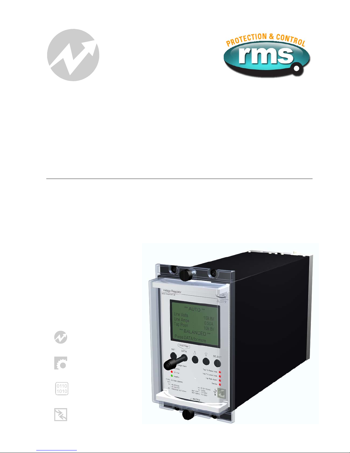
Voltage Regulating & Control Relay
relay monitoring systems pty ltd
Advanced Protection Devices
User Guide
Test Manual
Relay Software
µ
MATRIXwin

2V164-S
User Guide
About This Manual
This User Guide covers all 2V164-S relays manufactured from April 2009. Earlier relays do not
necessarily incorporate all the features described. Our policy of continuous may means that extra
features & functionality may have been added.
The 2V164-S User Guide is designed as a generic document to describe the common operating
parameters for all relays built on this platform. Some relay applications are described but for specific
model information the individual “K” number Product / Test manuals should be consulted.
The copyright and other intellectual property rights in this document, and in any model or article produced
from it (and including any Registered or unregistered design rights) are the property of Relay Monitoring
Systems Pty Ltd. No part of this document shall be reproduced or modified or stored in another form, in any
data retrieval system, without the permission of Relay Monitoring Systems Pty Ltd, nor shall any model or
article be reproduced from this document without consent from Relay Monitoring Systems Pty Ltd.
While the information and guidance given in this document is believed to be correct, no liability shall be
accepted for any loss or damage caused by any error or omission, whether such error or omission is the
result of negligence or any other cause. Any and all such liability is disclaimed.
Contact Us
©Relay Monitoring Systems Pty Ltd 2001-2009
6 Anzed Court • Mulgrave 3170 • AUSTRALIA
Phone 61 3 9561 0266 • Fax 61 3 9561 0277
Email [email protected] • Web www.rmspl.com.au
To download a PDF version of this guide:
http://www.rmspl.com.au/userguide/2v164-s_user_guide.pdf
To download the model specific Test Manual:
http://www.rmspl.com.au/search.asp

How this guide is organised
This guide is divided into five parts:
Part 1 Overview
About this Manual
Contents
Test Manual
Mechanical Configuration
Description of Operation
L
ine Drop Compensation
Part 2 Technical Bulletin
Part 3 Software Function
Compatible Software
Factory Default Software
Determining Software UMX
Determining UMX Functionality
User Interface
Field Calibration
Part 4 Installation
Handling of Electronic Equipment
Safety
Unpacking
Accessories
Storage & Handling
Recommended Mounting Position
Relay Dimensions & Other Mounting Accessories
Equipment Connections
Part 5 Maintenance
Mechanical Inspection
Test Intervals
Defect Report Form
Visit www.rmspl.com.au for the latest product information.
Due to RMS continuous product improvement policy this information is subject to change without notice. 2V164-S_Guide/Iss A - 01/04/09

Part
1
Test Manual
This User Guide covers all 2V164-S relay versions & describes the generic features & attributes
common across all versions.
Different relay versions are required to cater for varying customer requirements such as auxiliary
voltage range, I/O configuration, case style, relay functionality etc.
The product ordering code described in the Technical Bulletin is used to generate a unique
version of the relay specification & is called a type number. The type number takes the form
2V164-SKxx where the Kxx is the “K” or version number.
Refer to: www.rmspl.com.au/handbook/parta3.pdf
for a complete description of the RMS “K” number system.
Each 2V164-S version has a specific Test Manual which provides details on the unique attributes
of the relay. Each Test Manual includes the following information:
•Test Certificate
•Specific technical variations from the standard model if applicable
•Test & calibration record
A Test Manual is provided with each relay shipped.
A CD & serial comms. cable is supplied with each relay order.
If you require a copy of the Test Manual for an RMS product the following options are available:
•Check the RMS web site at: www.rmspl.com.au/search.asp
•RMS CD catalogue select: List all Product/Test Manuals under Technical Library
•Contact RMS or a representative & request a hard copy or PDF by email.
Visit www.rmspl.com.au for the latest product information.
Due to RMS continuous product improvement policy this information is subject to change without notice. 2V164-S_Guide/Iss A - 01/04/09
Mechanical Configuration
Great care has been taken to design a rugged, cost effective & flexible mechanical solution for
the MATRIX range of RMS protection relays. The MATRIX range provides a compact draw out
case solution with M4 screw terminals:
•2M28 Size 2 with 28 terminals
•4M28 Size 4 with 28 terminals
•4M56 Size 4 with 56 terminals
Complete details & attributes for the M (MATRIX) cases & accessories may be found at:
http://www.rmspl.com.au/mseries.htm
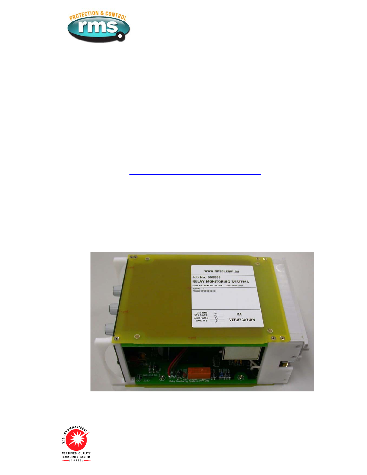
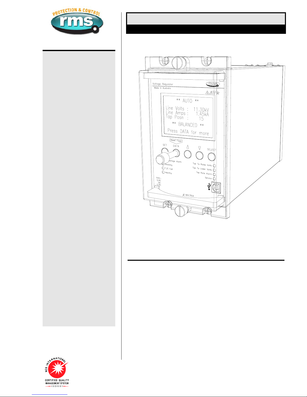
The 2V164-S is configured in a 4M56-S case & the following photographs depict the general
mechanical configuration. It should be noted that re-usable JIS plastic threading (PT type) screws
are used to bind the draw out relay module.
Visit www.rmspl.com.au for the latest product information.
Due to RMS continuous product improvement policy this information is subject to change without notice. 2V164-S_Guide/Iss A - 01/04/09
Image of generic inner relay module after removal from the outer case.
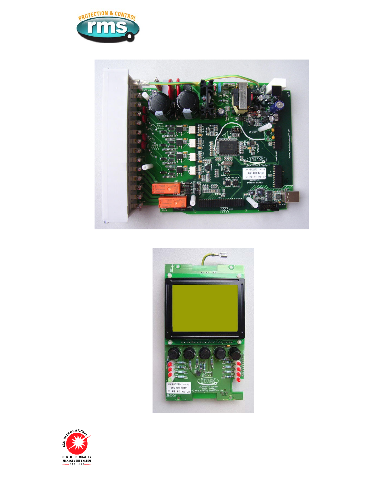
Primary circuit board showing the wide range power supply at the top.
Front panel circuit board showing graphic LCD panel and push buttons.
Visit www.rmspl.com.au for the latest product information.
Due to RMS continuous product improvement policy this information is subject to change without notice. 2V164-S_Guide/Iss A - 01/04/09

Secondary circuit board showing analogue voltage and current channels.
Optional network communications circuit board with additional I/O.
Visit www.rmspl.com.au for the latest product information.
Due to RMS continuous product improvement policy this information is subject to change without notice. 2V164-S_Guide/Iss A - 01/04/09
Description of Operation
The 2V16x Series relays are designed for the control of motor driven on-load power transformer
tap changers.
The 2V164-S Voltage Regulator Relay continuously monitors the transformer output voltage &
current & provides "RAISE" & "LOWER" control commands to the on-load tap changer such that
the load centre is automatically maintained within acceptable limits. Small variations in supply
frequency will not affect the system performance.
When designing the 2V164-S, considerable emphasis was placed on producing a relay, which
would be very simple to install, set up & operate in the field. The result is a simple yet effective &
very dependable voltage regulator relay available at a competitive price. The standard Micro
MATRIX human machine interface (HMI) is combined with fully solid state voltage sensing &
measuring circuitry to provide high accuracy, simple set up & flexible operation.
Visit www.rmspl.com.au for the latest product information.
Due to RMS continuous product improvement policy this information is subject to change without notice. 2V164-S_Guide/Iss A - 01/04/09

Line Drop Compensation
The line drop compensation, i.e. the inclusion of the voltage drop of a line connected to the
transformer in the regulating process, can be accomplished in two different ways. Two modes are
available:
Z-Compensation
Z-compensation is easier to set than the vectorial compensation method and is suitable where
only small shifts in the phase angle cosΦare experienced.
Vectorial compensation (Four setting modes: +PHASE and +QUAD)
Vectorial compensation is more difficult to set as exact line data must be known but is more
accurate when set correctly.
Setting the LDC Mode of Operation
Six settings are selected in the 2V164-S from the LDC menu as follows:
LDC mode: OFF LDC inactive
+ PHASE Use when relay wired in phase configuration
- PHASE Use when relay wired in phase configuration
+ QUAD Use when relay wired in quadrature configuration
- QUAD Use when relay wired in quadrature configuration
Z-COMP Use when relay wired in phase configuration
Visit www.rmspl.com.au for the latest product information.
Due to RMS continuous product improvement policy this information is subject to change without notice. 2V164-S_Guide/Iss A - 01/04/09

Z Mode LCD Compensation Setting
Z-Compensation may be employed with the relay wired in phase or in quadrature configuration
where only small shifts in the phase angle cosΦare experienced.
The calculated percentage of the voltage rise, referred to the voltage level, set at the 2V164-S
LDC menu Z-Comp value in % as per the following formula:
Voltage rise % = 100 . UTr - ULoad . IN. RCT
______________ __________
U
Load
I
Where:
Voltage rise = setting of Z-compensation in %
UTr = transformer voltage at current I
ULoad = line end voltage at current I and with the same service position of the tap
changer
I= load current in amps
IN= rated current in amps of the selected current transformer connection to the
voltage regulator, i.e. 1A or 5A
RCT = current transformer ratio e.g. 200A/5A
Check the Z-compensation operation using the following steps:
1. Set Z-compensation voltage rise to 0%;
2. Apply a voltage to achieve balanced state;
3. Set Z-compensation voltage rise to 15%;
4. A voltage raise LED must light up when a load current of 10% of the rated current input is
applied;
5. Now carry out the required setting of the Z-compensation as per the above formula.
Visit www.rmspl.com.au for the latest product information.
Due to RMS continuous product improvement policy this information is subject to change without notice. 2V164-S_Guide/Iss A - 01/04/09

Vectorial Compensation (Phase and quadrature mode) LDC setting
Refer to the wiring diagram to choose the appropriate mode setting. The negative modes simply
reverse the sense of the compensation voltage which is more convenient than changing the
wiring polarity.
For the correct setting in these modes it is necessary to calculate the resistive and inductive line
voltage drop, referred to the secondary side of the voltage transformer in V and the correct
setting of the existing measuring transformer configuration according to the following formula:
RCT
Ur= IN. . r . L Volts
____
R
VT
RCT
Ux= IN. . x . L Volts
____
R
VT
Where:
Ur= LDC setting for resistive line voltage drop in Volts
Ux= LDC setting for inductive line voltage drop in Volts
IN= rated current in A of the selected current transformer connection to the voltage
regulator, i.e. 1A or 5A
RCT = current transformer ratio, e.g. 200A/5 Amps
R33,000V / √3
VT = voltage transformer ratio: e.g. IN PHASE connection wiring
________________
110V
33,000V
Visit www.rmspl.com.au for the latest product information.
Due to RMS continuous product improvement policy this information is subject to change without notice. 2V164-S_Guide/Iss A - 01/04/09
e.g. IN QUAD connection wiring
___________
110V
r= ohmic resistance of the line in ohm/km per phase
x= inductive reactance of the line in ohm/km per phase
L= length of the line in km

The resistive and reactive line drop compensation settings are entered into the 2V164-S at the
LDC page in volts.
Check the vectorial compensation operation using the following steps:
1. Set the Resistive and Reactive voltage settings to 0V;
2. Set the LDC mode to +PHASE or +QUAD based on the wiring configuration used;
3. Apply a voltage to achieve balanced state;
4. Set the Reactive voltage (Ux) setting to 15V;
5. A voltage raise LED must light up when the rated current input is applied at 90 degree lag
relative to the line voltage;
6. Set the LDC mode to -PHASE or -QUAD based on the wiring configuration used;
7. A voltage lower LED must light up when the rated current input is applied at 90 degree lag
relative to the line voltage;
8. Now carry out the required setting of the LDC Resistive (Ur) and Reactance (Ux)
compensation as per the above formula.
Provided the resistive and inductive line voltage drops Urand Uxare correctly set the voltage at
the load end will remain constant, independent of the load current.
Visit www.rmspl.com.au for the latest product information.
Due to RMS continuous product improvement policy this information is subject to change without notice. 2V164-S_Guide/Iss A - 01/04/09

Part
2
Technical Bulletin
The detailed technical attributes, functional description & performance specifications for the
V164-S are described in the attached Technical Bulletin. For the most up to date version go to:2
www.rmspl.com.au/handbook/2v164-s.htm
For any specific attributes of a particular version refer to the Test Manual for that type (K)
number.
The order of precedence for technical information is as follows:
•Test Manual
•Technical Bulletin
•User Guide
Visit www.rmspl.com.au for the latest product information.
Due to RMS continuous product improvement policy this information is subject to change without notice. 2V164-S_Guide/Iss A - 01/04/09
Visit www.rmspl.com.au for the latest product information.
Due to RMS continuous product improvement policy this information is subject to change without notice. 2V164-S/Issue F/08/04/11 - 1/9
Features
SYSTEM FEATURES
Large back lit display panel
System status LED indicators
Simple menu setting procedure
Wide auxiliary supply range
with fail alarm contact
Self diagnosis and fail alarm
Size 4M56-S draw out case
Made in Australia
VOLTAGE CONTROL
Line drop compensation with
1A and 5A CT inputs
Z Compensation
63.5 and 110V AC VT inputs
Definite time and inverse time
delays
Independent fine and coarse
voltage bandwidth windows
Over and under voltage alarms
Under voltage blocking function
Tap change fail alarm
Two digital input load step
stages
Overcurrent blocking
METERING AND EVENT RECORDING
Line voltage display
Line current display
Tap position indicator
Tap rate of change alarm
Tap change event counter
Tap position mA output
Line voltage mA output
COMMUNICATION
USB front programming port
Non platform specific PC
programming software:
µ
MATRIXwin
Optically isolated RS485
network communication port
MODBUS RTU compatible
network protocol
Technical Bulletin 2V164-S
Voltage Regulating & Tap Change Control Relay
2V164-S depicted in a size 4M56-S draw out case
Application Made in Australia
The 2V164 Series relays are designed for the control of motor driven on-load power
ransformer tap changers.t
The 2V164 Voltage Regulator Relay continuously monitors the transformer output voltage
and current and provides "RAISE" and "LOWER" control commands to the on-load tap
changer such that the load centre is automatically maintained within acceptable limits. Small
ariations in supply frequency will not affect the system performance.v
When designing the 2V164, considerable emphasis was placed on producing a relay, which
would be very simple to install, set up and operate in the field. The result is a simple yet
effective and very dependable voltage regulator relay available at a competitive price. The
standard Micro MATRIX human machine interface (HMI) is combined with fully solid state
voltage sensing and measuring circuitry to provide high accuracy, simple set up and flexible
peration.o
PARALLEL CONTROL SCHEMES
Parallel control schemes are available to meet a range of transformer control configurations
based on the master / follower principal. These systems are supplied fully wired in 19” sub
rack frames ready for integration into customer panels. Up to 4 transformers operating in
arallel on one or two groups are possible.p
For further details refer to the RMS 1M122A, 1M122D and 2V165 technical bulletins which
rovide details on our range of transformer parallel control systems.p
Visit www.rmspl.com.au for the latest product information.
Due to RMS continuous product improvement policy this information is subject to change without notice. 2V164-S/Issue F/08/04/11 - 2/9
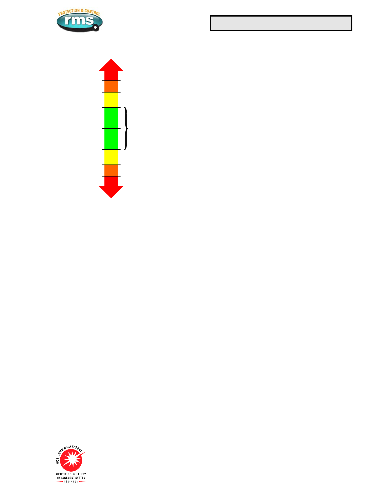
+ Fine bandwidth
+ Coarse bandwidth
- Coarse bandwidth
- Fine bandwidth
Initial / interval tap raise
Initial / interval tap lower
Fast tap down
Fast tap raise
Tap raise blocked & U/V alarm
Fast tap down & O/V alarm
Setpoint voltage
VOLTS HIGH
VOLTS LOW
Balanced voltage
O/V Alarm
U/V Blocking
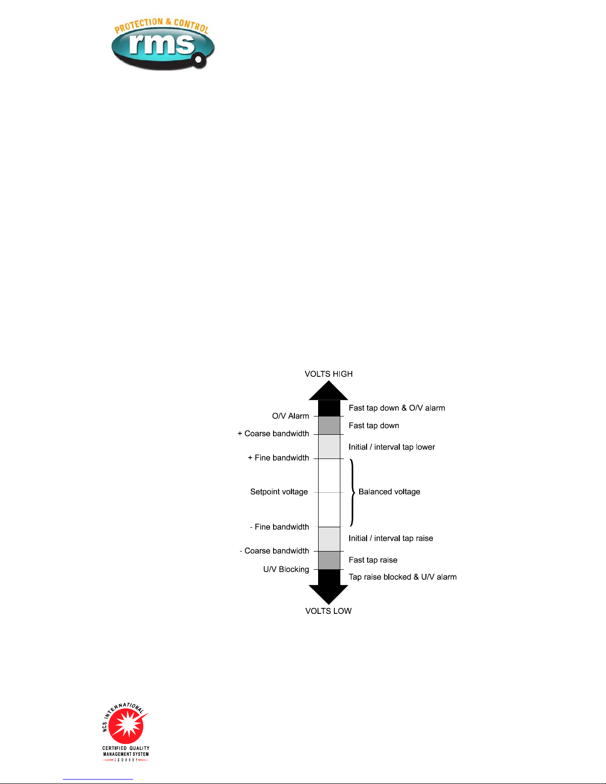
Figure 1: User defined voltage set points
SETPOINT VOLTAGE RANGE
90V to 130V in 0.1V steps.
110V and 63.5V nominal inputs.
“FINE” VOLTAGE BANDWIDTH SETTING (SENSITIVITY)
0.3 V to 5.0V in 0.1V steps.
The bandwidth setting should be made in accordance with the
relative step voltage of the tap changer. A narrow bandwidth may
result in the tap changer hunting between adjacent taps.
INITIAL RAISE / LOWER TIMER
10s to 300s in 10s steps.
The initial time delay between the detection of an error in the
monitored voltage and the resultant tap change output, is switch
selectable as either a definite time or true inverse time response.
The initial time delay starts when the voltage deviation exceeds
the upper or lower limit. The respective instantaneous HIGH /
LOWER LED illuminates.
If the deviation falls back to within bandwidth limits before the pre
set time delay is completed, the timer is reset.
At the completion of the pre set time delay the respective RAISE /
LOWER tap output contact will close.
INTERVAL TIME DELAY
1s to 100s in 1s steps.
The interval time delay only becomes active when the initial delay
has caused a tap change but without affecting a balanced
condition, ie. if more that one tap change operation is necessary
to bring the voltage within set limits.
INVERSE TIME DELAY CHARACTERISTIC
In the inverse time mode, the initial time delay is inversely
proportional to the ratio of deviation to bandwidth down to a
minimum of a one-second delay. For example:
♦When the detected error is equal to the selected bandwidth the
time delay is equal to the delay setting.
♦For a detected error of N times the selected bandwidth, the
time delay is 1/N times the delay setting.
Voltage Control Functions
“COARSE” VOLTAGE BANDWIDTH SETTING
1V to 20V in 1V steps.
1s to 60s in 1s steps.
A second independent voltage control window can be set with a
definite time delay. This can be used for a fast tap change
function for large voltage deviations, which are outside the fine
bandwidth window.
UNDER VOLTAGE BLOCKING FUNCTION
60V to 90V in 1V steps.
0s to 60s in 1s steps.
An undervoltage blocking function is combined with a definite
time delay output.
Undervoltage blocking suppresses tap change operations during
a system breakdown to avoid the tap changer mechanism from
being driven to the top tap. The self reset Blocking alarm relay is
activated when this element has timed out and a message
reported on the HMI.
OVER VOLTAGE ALARM
110V to 140V in 1V steps.
0s to 60s in 1s steps.
An overvoltage alarm is combined with a definite time delay
output. The self reset overvoltage alarm relay contact is activated
when this element has timed out and a message reported on the
HMI.
OVER CURRENT BLOCKING
50 to 150% in 5% steps – Can also be set to OFF
0s to 60s in 1s steps
Reset: >0.97Iset
When timed out all tap commands are inhibited / cancelled.
The self reset Blocking alarm relay is activated when this element
has timed out and a message reported on the HMI.
LINE DROP COMPENSATION
Resistance and reactance compensation: 0V to 20V in
0.1V steps
Settings are provided to cater for in phase and in quad
connections, with either positive or negative reactance
compensation.
Correct setting of the LDC requires the calculation of the resistive
and reactive line-drops as a voltage with reference to the
secondary side of the VT and the setting of the instrument
transformer for IN PHASE or IN QUAD connection. Z
compensation is also available: 0 to +15% setting range.
The LDC function does not effect the under or over voltage alarm
set points. These operate from the direct voltage measurements.
VOLTAGE LOAD STEP INPUTS
-10% to +10% of the set point voltage in 0.5% steps
Two independent load step stages are provided. The voltage
reduction or boost level for each stage can be independently set
while a separate digital input is provided to initiate each stage. If
both stages are initiated then the stage 2 level is operative.
OPERATIONAL INDICATORS
Red LED’s on the front panel indicate the following conditions:
Over voltage Bus voltage above alarm setting
Blocking BUS voltage / current outside block settings
Tap change fail Tap change time out alarm
Raise volts Flash when timing / On for Raise tap initiate
Lower volts Flash when timing / On for Lower tap initiate
Tap rate Tap rate alarm level exceeded
TAP CHANGE FAIL ALARM
10s to 300s in 10s steps.
The tap change fail alarm timer is initiated when an out of
bandwidth voltage error is detected. Time out will result in the
alarm contact closing. The alarm timer and contact is reset when
he sensed voltage has moved back to a balanced condition.t
AUTO / MANUAL MODE CONTROL INPUT
A digital input is provided to change the relay from AUTO to
ANUAL mode.M
In AUTO mode the 2V164 will monitor the voltage and current
inputs and output tap raise / lower commands to maintain the load
enter in accordance with the relay settings.c
In MANUAL mode tap raise and lower commands are inhibited.
The Blocking and Overvoltage alarm outputs remain active.
The relay fail alarm remains active.
Visit www.rmspl.com.au for the latest product information.
Due to RMS continuous product improvement policy this information is subject to change without notice. 2V164-S/Issue F/08/04/11 - 3/9
TAP POSITION INDICATOR
A tap position indicator input is provided to enable the transformer
tap to be displayed on the HMI. The output from the RMS type
2V200 Tap Position Transducer is required for this function to
operate. Refer to the 2V200 Technical Bulletin for details.
TAP POSITION INDICATOR INPUT
For this function to operate an RMS type 2V200 transducer /
sender unit is required at the tap changer. Refer to the 2V200
Technical Bulletin for application details.
The 2V200 is designed to interface to tap changes and convert
one of the following parameters:
an analogue voltage signal proportional to the tap position
a binary coded decimal signal
a BCD signal
The 2V200 converts any of these inputs to a frequency signal
proportional to the tap position.
The 2V164 VRR is then simply programmed with the number of
tap positions within the range 10 to 30. Scaling is carried out
automatically so that the correct tap position is indicated on the
2V164 display.
A 4-20mA analogue output proportional to tap position is also
provided by the 2V164 for local panel indication or interface to
SCADA.
VOLTAGE DISPLAY
The HMI displays the line voltage. The VT ratio may be entered so
that the HMI display reads in primary voltage. A 4-20mA analogue
output is also provided.
Display range (Secondary): 10-145V
VT setting range: 0.11KV to 132.00KV
CURRENT DISPLAY
The HMI displays the line current from the LDC input. The CT
ratio may be entered so that the HMI display reads in primary
current.
Display range (Secondary): 0.1-1.35Is
CT setting range: 1A to 6.00KA
Metering & Event Logging
TAP CHANGE EVENT COUNTER
A record is maintained and displayed of the number of tap
operations since this function was last reset. The tap rate
indicator takes account of all tap changes initiated by the 2V164
tap raise / lower contacts. Manual taps initiated by external
control contacts are not included.
RANGE OF TAP OPERATION
A record is maintained and displayed of the minimum and
maximum tap position reached since this function was last reset.
TIME ELAPSED SINCE TAP COUNT RESET
A record is maintained and displayed of the time in hours since
the tap count was last reset.
TAP RATE ALARM
The 2V164 records and displays the rate at which tap raise/lower
commands have been output over the preceding 15-minute
period. If the set point rate is exceeded (taps per hour), an alarm
contact is picked up. This alarm contact is automatically reset
when a tap rate lower than the alarm set point is updated to the
display or when the tap count is manually reset. The tap rate
indicator takes account of all tap changes initiated by the 2V164
tap raise / lower contacts. Manual taps initiated by external
control contacts are not included.
TAP POSITION INDICATOR ANALOGUE OUTPUT
A single tap position indicator analogue output signal is provided
for interface to an RTU. The analogue output is linked to the tap
position as follows:
Output: 4 to 20mA
Compliance voltage: 5V
Maximum burden: 250 Ohms
Accuracy: +/-3%
Analogue output:
Tap 1 4mA
Tap N 20mA
Where N = maximum selected tap setting
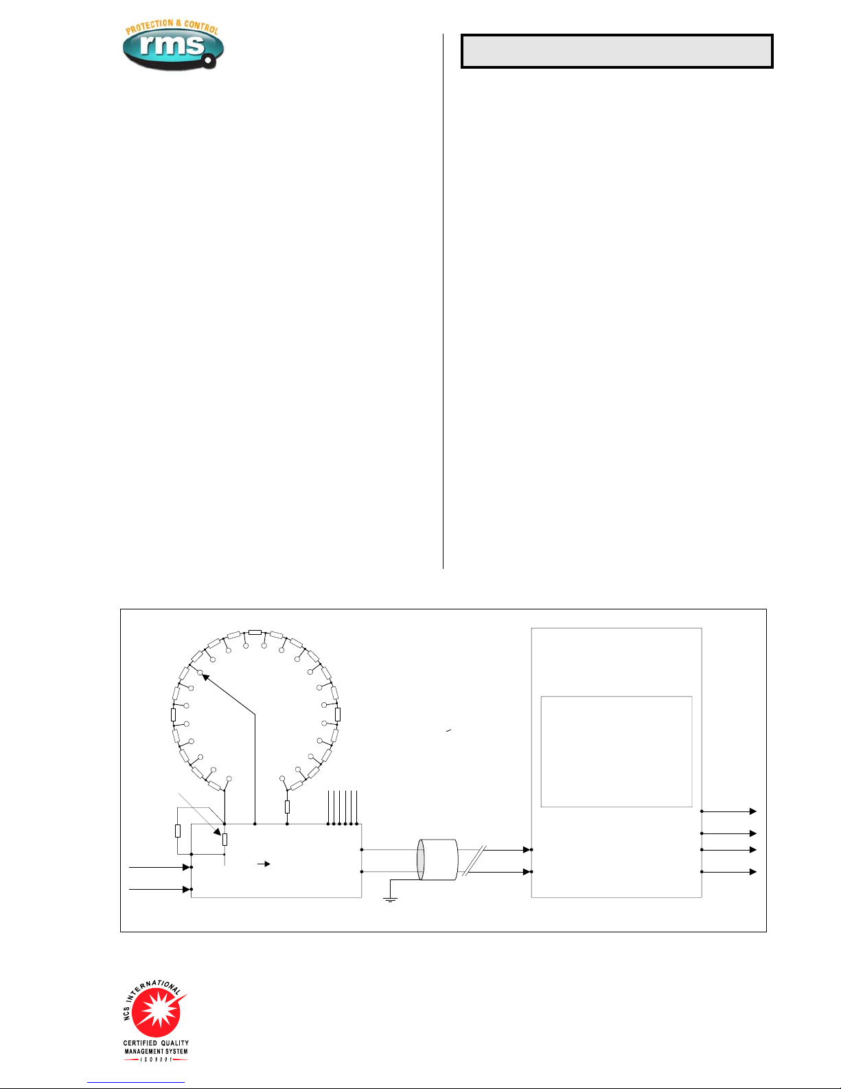
Ta p 1
Use 400 Ohm 1% 0.5W resistors for Rs
Other resistor values possible:
refer 2V200 Technical Bulletin
for tap 1 reference
padding resistor (Rp) values
Rs 1 Rs 21
Ra*
Tap position indicator (TPI) hardware requirements and wiring configuration.
Transformer TPI selector switch
Frequency
output
Shielded cable recomended
for long runs & parallel control
(2V165), applications
5KHz Max.
Integrated TPI display
** T/C EVENTS PAGE **
DATA to return
V F TPI
Transducer & sender unit
Ta p R a t e :
Max Tap:
Min Tap:
Tap Count:
Time Elapsed:
4
18
4
620
160
2V164 VRR
2V200
11 15
16
1
2
13 1012 4 5
The RMS type 4O200 Resistor Box
provides a packaged TPI Rs solution
TPI output
Volts output
Alternative
Binary or BCD coded interface
Ta p 1
internal
reference
resistor
(400 ohms)
** Tap 1
external
padding
resistor
Rp
Vx
110V AC
or 240V AC
* If Rs x number taps > 600 ohms
then resistor Ra is not required.
** If Rs = 400ohm
then resistor Rp is not required.
Figure 2

Visit www.rmspl.com.au for the latest product information.
Due to RMS continuous product improvement policy this information is subject to change without notice. 2V164-S/Issue F/08/04/11 - 4/9
RELAY CONFIGURATION USING
µ
MATRIXwin
The purpose of the
µ
MATRIXwin application is to provide display,
configuration and diagnostic facilities required to support the
entire family of
µ
MATRIX digital relays. The prime functions of the
application are:
Create a setting file off line
To create and view relay setting files at your PC without the need
for a relay;
Relay setting
To down load a setting file (UMP) into a relay connected to a PC;
To display and change settings in a connected relay;
Relay status
To display the Status of nominated inputs and outputs of a
connected relay;
Relay Control
Manual raise / lower commands and resetting functions can be
performed;
Commissioning
To export reports of setting parameters and status screen to
confirm correct functionality during commissioning;
Upgrade relay software
To configure a
µ
MATRIX relay for a specific customer application;
To upgrade the operational software (UMX) of a
µ
MATRIX relay;
All current UMX software applications may be downloaded from:
www.rmspl.com.au/umatrix
Maintenance
To provide utility and diagnostic facilities at a technical level.
Communications
COMMUNICATION PORTS
Two (2) communications ports are available. The front USB
programming port is provided as standard while the rear RS485
network port is available as an option.
Programming port
The programming port is accessible from the front panel of the
relay via a USB physical link and PC configuration program
supplied with the relay. The
µ
MATRIXwin configuration program
is designed to operate with all relays from the
µ
MATRIX range
and with all installed firmware version.
Network port
The network port is intended for applications where permanent
connection to a master control system is required. An optically
isolated RS485 physical layer is provided for this function.
The RS485 connection is intended for applications where multiple
µ
MATRIX relays are to be connected on a common
communications bus.
Network Port Terminating Resistor
Where multiple relays are connected in a multi-drop configuration
the RS485 comms. bus must have a 120 ohm terminating resistor
fitted at each end. If the
µ
MATRX-S relay is at one end of the
transmission line a terminating resistor can be added by placing
SW100-3 and SW100-4 in the ON position as depicted in the
wiring diagram.
Network Port BIAS Resistors
Where a single relay is connected to the network, or where the
relay is a long distance from other devices on the comms. bus,
BIAS resistors may need to be fitted to ensure reliable operation.
To simplify this configuration, BIAS resistors are fitted to each
µ
MATRIX-S relay and may be selected IN by setting switches
SW100-1 and SW100-2 to the ON position as depicted in the
wiring diagram. This bank of four switches can be accessed by
withdrawing the relay module from it’s case, turning upside down
and looking at the centre PCB near the rear terminal blocks.
PC TO
µ
MATRIX USB CONNECTION
2V164-S front panel USB programming port
USB DRIVERS
The uMATRIX-S USB port is configured as a Virtual
Communications Port (VCP) and is operated through a PC COM
port. USB drivers must be installed on the PC to enable correct
communication. A ZIP file containing the driver files needed for
this process may be downloaded from:
www.rmspl.com.au/umatrix

Visit www.rmspl.com.au for the latest product information.
Due to RMS continuous product improvement policy this information is subject to change without notice. 2V164-S/Issue F/08/04/11 - 5/9
VOLTAGE SENSING CIRCUITRY
Nominal monitoring voltage
IN QUAD connection: 110V 50HZ
I
N PHASE connection: 63.5V 50Hz
Sensing supply burden: Less than 0.2VA
T
hermal rating: 300V continuous
N
ominal sensing frequency: 40 to 60Hz
Voltage measurement secondary accuracy (110V tap):
Precision of voltage setting: 0.1V steps
Voltage pick up repeatability: +/-0.1V from 90 to 120V
Voltage measurement resolution: 45mV
Resolution of voltage display: 0.1V
A
ccuracy of displayed voltage: +/-0.1V from 90 to 120V
ACCURACY OF TIMERS
All timers +/-0.1s
LINE DROP COMPENSATION (LDC) INPUT
Nominal sensing current: CT taps for 1A and 5A inputs
LDC input burden: <0.5VA
Thermal rating: 3x nominal continuous
3.5x nominal for 10 minutes
6x nominal for 2 minutes
100A for 1s on 1A input
350A for 1s on 5A input
700A for 1 cycle on 1A input
2,500A for 1 cycle on 5A input
Note: M Series case terminals and CT shorting
switches are limited to 400A for 1s.
LDC accuracy: +/- 0.3V error at nominal 110V setting and 10 to
120% CT input
SET POINT HYSTERESIS
All voltage set points have a hysteresis equal to 50% of the
bandwidth voltage setting. Other values available on application.
Technical Data
TAP CHANGE FEEDBACK FUNCTION
When a tap change command is output to the OLTC, the tap
change fail timer is started. If a single tap change restores the
sensed voltage to a balanced condition the relay is reset. If the
sensed voltage remains in error the interval time delay will start
based on one of the three methods described below: The
required operating mode is selected using the UMX order code.
VOLTAGE MONITORING (Automatic mode) UMX2V164A
In this mode the 2V164 provides a 1s output pulse to initiate a tap
change. This output pulse is then repeated at a rate set by the
Interval Timer setting until the sensed voltage has moved back to
a balanced condition. This is the simplest connection method as it
does not require a hard-wired contact between the OLTC and the
VRR.
The output pulse may be selected as continuous for application
with linear voltage regulators. The continuous output contact and
interval timer delay is reset once the sensed voltage moves back
to the balanced condition.
OLTC AUXILIARY CONTACT METHOD UMX2V164B
In this mode an auxiliary contact on the OLTC is employed to
signal completion of a tap change sequence. This signal is used
by the 2V164 to pause the interval time delay until the previous
tap change sequence has been completed.
The default 2V164 T/C feedback status input is set for a control
voltage to be removed when the tap change starts (OLTC
auxiliary contact opens) and re-applied when the tap change
sequence is completed (OLTC auxiliary contact closes). The
interval time delay is paused until the completion of the tap
change sequence has been signaled.
The output pulse may be selected as continuous or to provide a
1s pulse output.
The continuous output contact and interval time delay is reset
once the sensed voltage moves back to a balanced condition.
TPI FEEDBACK METHOD UMX2V164C
In this mode the 2V200 TPI transducer must be connected as per
figure 2. The control sequence is as follows:
1. A voltage deviation starts the initial time delay.
2. The time delay expires and a tap change command is output.
3. The tap change contact will remain closed until a signal is
received from the TPI transducer confirming that a tap
change event has occurred.
4. The interval time delay is initiated.
5. Sequence 2 to 4 will repeat at the rate determined by the
Interval timer setting until the sensed voltage has moved back
to a balanced condition.
TAP POSITION TRANSDUCER FAIL (UMX2V164C only)
In the event that a 2V200 TPI transducer loses connection to the
2V164 or fails, any pending tap commands are blocked.
For TPI transducer (2V200) failure conditions, a ‘TPI Fail’
message is displayed on the MMI and the tap position displays as
‘TPI Offline’. The TPI fail output contact is also set.
Normal tap change feedback and voltage regulation control
function is automatically restored once the TPI transducer signal
is recovered.
It should be noted that the ‘TPI fail alarm’ and the ‘Tap change fail
alarm’ share a common output contact.
LINE VOLTAGE ANALOGUE OUTPUT
Output: 4 to 20mA
Compliance voltage: 5V
Maximum burden: 250 Ohms
Accuracy: +/-3%
Analogue output: Lower (4mA) set point range: 0V - 146V
Upper (20mA) set point range: 50V - 146V

Visit www.rmspl.com.au for the latest product information.
Due to RMS continuous product improvement policy this information is subject to change without notice. 2V164-S/Issue F/08/04/11 - 6/9
STATUS INPUT MINIMUM OPERATING CURRENT
1
0 mA P/U for 1 ms then reducing to1.5 mA after 4 ms.
S
TATUS INPUT OPERATING TIME
Initiate input Parameter Delay
P/U <4 ms
DC D/O <16 ms
P/U <23 ms
AC D/O <33 ms
Technical Data
AUXILIARY SUPPLY
20-70V DC switchmode supply or
40-275V AC / 40-300V DC switchmode supply
Burden: Less than 10 watts with all output relays energized
using 110V DC nominal supply.
Inputs:
A high efficiency switchmode power supply is incorporated which
provides a low burden to the auxiliary supply.
Input Transients:
Withstands multiple high-energy transients and ring waves in
accordance with IEEE28 - ANSI C26.1 Cat. II, accordingly:
0.5uS 100kHz 6kV O/C, 500A S/C, 4J
1.2/50uS 6kV O/C
8/20uS 3kA S/C, 80J clamped at 1,000V
Mains conducted EMI within limits specified by AS 3548 Class B.
Isolation:
The inputs are isolated from the outputs in accordance with
AS3260 Class II Limited Current Circuitry, accordingly:
Withstand voltage of 2.5kV RMS 50Hz for one minute
Creepage and clearance distance greater than 4mm
Output leakage current less than 0.25A to earth
Output Protection:
Outputs will withstand continuous short circuit. Output regulators
and switching control regulator are thermally protected.
RELAY FAIL ALARM
A C/O alarm contact is maintained in the energized state when all
of the following conditions are met:
The auxiliary supply is applied
The internal 24V DC rail is within acceptable limits
The CPU hardware watchdog maintains a pulsing output
A CPU software watchdog records “suspect” events to an assert
register and if necessary performs a soft restart.
A front panel green LED is illuminated when the relay is healthy.
A separate flashing red LED indicates a software problem has
been encountered which caused causing the CPU to perform a
arm boot.w
CASE
Size 4 draw out with 56 M4 screw terminals
Flush panel mount or 4U high 1/4 width 19 inch rack mount
I
P51 rating
SHIPPING DETAILS
Each relay is supplied individually packed in pre formed
cardboard cartons with internal moulded polystyrene former.
Weight: 3.5Kg
S
ize: 370(L) x 240(W) x 145(D)mm - Size 4 case
For large shipment individual cartons are packed in sturdy
cardboard pallet boxes and surrounded by loose fill to absorb
ibration and shock during transit.v
ACCESSORIES SUPPLIED
1 x M4 self threading mounting screw kit P/N 290-406-151
2 x M4 terminal screw kit (28 per kit) P/N 290-407-153
1 x
µ
MATRIX User Guide per order
1 x USB cable per order
1 x CD -
µ
MATRIXwin software, setting files and applications per
order

Visit www.rmspl.com.au for the latest product information.
Due to RMS continuous product improvement policy this information is subject to change without notice. 2V164-S/Issue F/08/04/11 - 7/9
Technical Data
OUTPUT CONTACT RATINGS IEC60255-0-2
Carry continuously 5A AC or DC
0.5 s 20 A AC or DCMake and carry
L/R ≤40ms & V ≤300V 0.2 s 30 A AC or DC
AC resistive
AC inductive
1,250 VA
250 VA @ PF ≤0.4
DC resistive 75 W
Break capacity
I ≤5A and V ≤300V
30 W @ L/R ≤40 ms
DC inductive 50 W @ L/R ≤10 ms
Minimum number of operations 106at maximum load
Minimum recommended load 0.5W limit 10mA / 5 V
TRANSIENT OVERVOLTAGE IEC60255-5 CLASS III
Between all terminals and earth 5 kV 1.2/50 us 0.5 J
Between independent circuits without
damage or flashover 5 kV 1.2/50 us 0.5 J
INSULATION COORDINATION IEC60255-5 CLASS III
Between all terminals and earth 2.0 kV rms for 1 min.
Between independent circuits 2.0 kV rms for 1 min.
Across normally open contacts 1.0 kV rms for 1 min.
AUXILIARY SUPPLY IEC60255-11
Allowable breaks / dips in supply
Collapse to zero from nominal voltage ≤20 ms
HIGH FREQUENCY DISTURBANCE IEC60255-22-1 CLASS III
2.5 kV 1MHz common mode
1.0 kV 1MHz differential mode ≤3% variation
ELECTROSTATIC DISCHARGE IEC60255-22-2 CLASS III
6 kV contact discharge ≤5% variation
FAST TRANSIENT IEC60255-22-4
4 kV, 5/50 ns, 100 KHz repetitive ≤3% variation
TEMPERATURE RANGE IEC68-2-1/2
Operating: -5 to +55oC
Storage: -25 to +75oC
HUMIDITY IEC68-2-78
40 oC and 95% RH non condensing
Front view 4 holesof 3.7
Indicative
position
Sideview
Size 4M56-S
drawout case
Drawingunits:mm
Terminallayout Panelcutout
Suits flush panelmounting &
4U high 19 inch rack frame
15
129230
27 5528 56
Table of contents
Other RMS Protection Device manuals


