ROBBE SCHLUTER Moskito Sport II User manual

S 2884
II

Inhaltsverzeichnis Contents Table
Technische Daten:
Rotordurchmesser: ca. 1280 mm
Heckrotordurchmesser: ca. 275 mm
Länge: ca. 1280 mm
Höhe: ca. 420 mm
Fluggewicht: ca. 3600 g
Inhalt Seite
Vorwort 3/4
Hinweise 5-7
1.0 Montage Kupplung 8/9
2.0 Montage Autorotations- 14/15
freilauf:
3.0 Tankzusammenbau 16/17
4.0 Zusammenbau Oberteil, 18/19
Unterteil, Tank Schalldämpfer
5.0 Montage Pitchbrücke 20/21
6.0 Montage Taumelscheibe22/23
7.0 Heckrotorblatthalter 26/27
8.1 Montage Seitenleitwerk 28/29
9.0 Montage Kufenlande- 30/31
gestell
10.0 Montage Gestänge 32/33
Taumelscheibenanlenkung
11.0 Montage Rotorkopf 36/37
12.0 Montage Pitch- 36/37
kompensator
13.0 Kabinenhaube 44/45
14.0 Fertigstellen der 46/47
Hauptrotorblätter
15.0 Einbau der 50-57
Fernsteuerungskomponenten
16.0 Endkontrolle 58/59
17.0 Tips zur Program- 60-63
mierung der Fernsteuerung
Specification:
Rotor diameter: approx. 1280 mm
Tail rotor diameter: approx. 275 mm
Length: approx. 1280 mm
Height: approx. 420 mm
All-up weight: approx. 3600 g
Contents Page
Foreword 3/4
Notes 5-7
1.0 Fitting the clutch 8/9
2.0 Fitting the auto-rotation 14/15
freewheel
3.0 Assembling the fueltank 16/17
4.0 Assembling the top 18/19
section, bottom section,
fueltank, silencer
5.0 Fitting the collective 20/21
pitch bridge
6.0 Fitting the swashplate 22/23
7.0 Tail rotor blade holders 26/27
8.1 Fitting the vertical 28/29
stabilizer
9.0 Fitting the skid landing 30/31
gear
10.0 Fitting the swashplate 32/33
linkages
11.0 Fitting the rotor head 36/37
12.0 Fitting the collective 36/37
pitch compensator
13.0 Cabin 44/45
14.0 Completing the main 46/47
rotor blades
15.0 Installing the RC system 50-57
components
16.0 Final checks 58/59
17.0 Tips on programming 60-63
your transmitter
Caractéristiques techniques:
Diamètre du rotor: approx. 1280 mm
Diamètre du rotor ar. approx. 275 mm
Longueur: approx. 1280 mm
Hauteur: approx. 420 mm
Poids en ordre de vol: approx. 3600
Sommaire page
preface 3/4
mentions 5-7
1.0 Montage de l‘embrayage 8/9
2.0 Montage de la roue libre 14/15
d‘autorotation
3.0 Assemblage du réservoir 16/17
4.0 Assemblage de la partie 18/19
supérieure, de la partie
inférieure, du réservoir et du
silencieux.
5.0 Montage du levier du pas 20/21
6.0 Montage du plateau 22/23
cyclique
7.0 Porte-pales du rotor 26/27
arrière
8.1 Montage de la 28/29
dérive
9.0 Montage de l‘atterrisseur 30/31
10.0 Montage des tringles 32/33
d‘asservissement du plateau
cyclique
11.0 Montage de la tête du 36/37
rotor
12.0 Montage du compen- 36/37
sateur de pas
13.0 Verrière de cabine 44/45
14.0 Préparation des pales 46/47
du rotor principal:
15.0 Mise en place des 50-57
éléments de l‘ensemble de
réception
16.0 Contrôle final 58/59
17.0 Généralités concernant 60-63
la programmation de
l‘ensemble de radiocommande
2

3
Vorwort Foreword Préface
Das von Ihnen erworbene Modell
MOSKITO-Sport II stammt aus der
Robbe-Schlüter Hubschrauber-
Produktfamilie.
Das Modell ist aufgrund seiner
Konstruktion als Trainer in wenigen
Stunden aufzubauen.
Das für den Aufbau und Betrieb
benötigte Werkzeug und Zubehör
entnehmen Sie bitte dem separaten
Zubehörblatt.
Hinweise zur verwendeten
Fernsteuerungsanlage:
Alle in der Bauanleitung angegebenen
Gestängelängen und
Servohebellängen
beziehen sich auf die Verwendung
von robbe/Futaba Servos.
Bei Einsatz von Servotypen anderen
Fabrikats können diese Maße leicht
abweichen.
Als Antriebsmotoren können Motoren
von 6,5 - 8,5 cm
3
eingesetzt werden.
Das Kurbelwellengewinde muß
1/4'x 28 UNF betragen.
Die Bauanleitung ist nach Baugruppen
gegliedert und in einzelne, logisch
aufeinanderfolgende Baustufen
unterteilt. Jede Baugruppe ist
numeriert und entspricht jeweils der
Beutelnummer aus dem Baukasten.
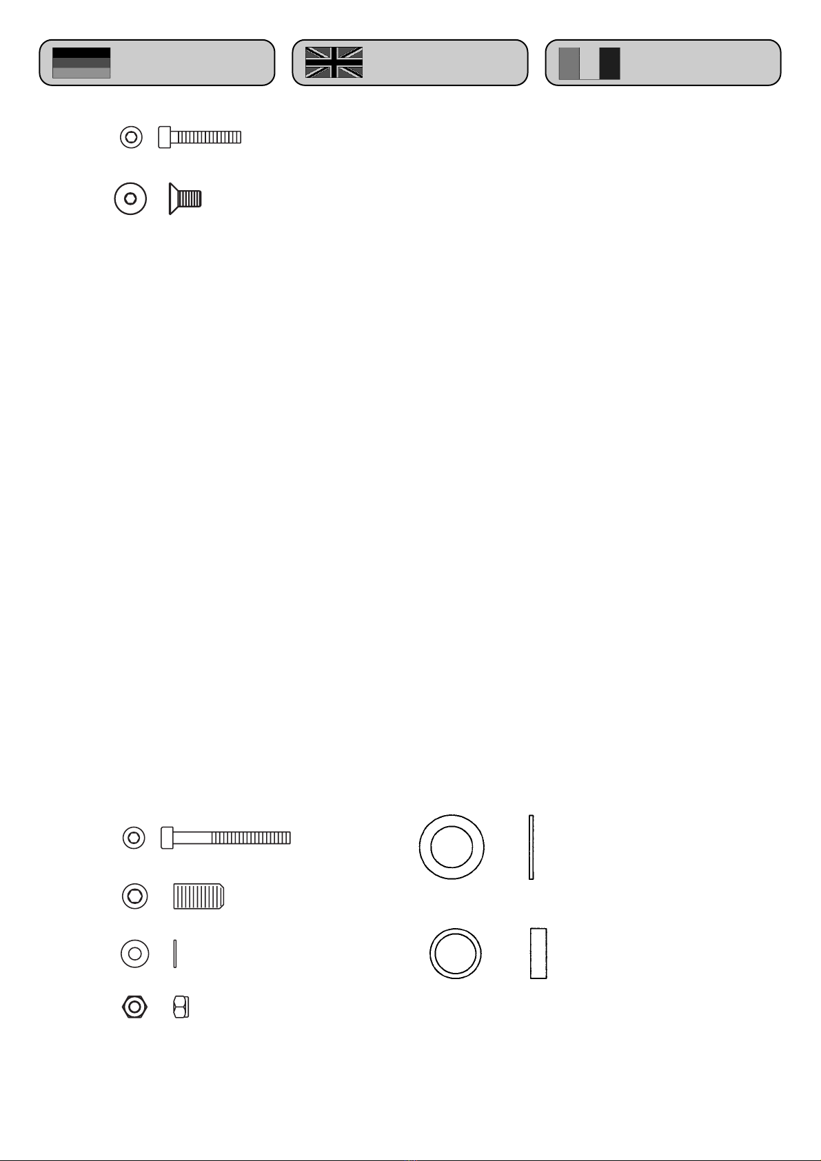
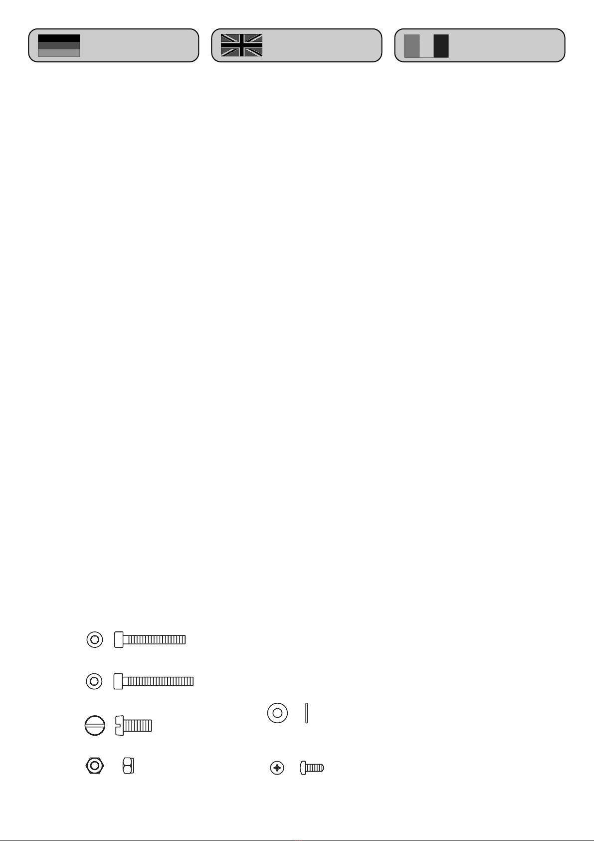
Zu jeder Baustufe erklärt eine
Montagezeichnung den
Zusammenbau. Zur Identifizierung der
Schrauben, Unterleg- und
Paßscheiben finden Sie bei jeder
Montagezeichnung eine Legende in
der diese Teile im Maßstab 1:1
dargestellt sind.
Bei jeder Baustufe finden Sie
ergänzende Hinweise, die bei der
Montage zu beachten sind.
Des weiteren finden Sie hilfreiche
Tips, die Ihnen auch bei dem
späteren Betrieb des Modells hilfreich
sein werden.
The MOSKITO-Sport II which you
have purchased is a member of the
renowned Robbe-Schlueter family of
helicopter products.
This compact model is of open trainer-
type construction and based on plastic
components. It is therefore easy to
assemble and can be ready to fly in
just a few hours.
Please refer to the separate accessory
sheet for details of the tools and
accessories required to build and
operate the model.
Notes on the radio control system:
All the pushrod lengths and servo
output arm lengths stated in the
building instructions assume the use
of Robbe/Futaba servos. If you are
using a different make of servo you
may need to make minor changes to
these values.
The model is designed to take a
glowplug motor of 6.5 - 8.5 cc
capacity. The crankshaft thread must
be 1/4“ x 28.
The building instructions are divided
into sub-assemblies which are then
sub-divided into individual logical
steps. Each sub-assembly is
numbered, and is built using the parts
from the bag bearing the same
number.
An assembly drawing is provided to
accompany each stage of
construction, and you will find this a
great help. Each drawing is supplied
with a full-size key to the screws,
washers and shim washers required,
so that you can be sure of using the
right parts.
Each stage contains useful
information relating to the task in
hand.
You will also find helpful tips which
are of more general guidance, and will
help you later when operating the
model.
Le modèle MOSKITO-Sport II que
vous venez d‘acquérir est un membre
de la famille des hélicoptères robbe-
Schlüter.
Ses caractéristiques de construction
en font un modèle d‘entraînement en
structure plastique compacte monté
en quelques heures.
L‘outillage et les accessoires
nécessaires au montage et à la mise
en úuvre du modèle sont mentionnés
sur un feuillet autonome.
Recommandations concernant
l‘ensemble de radiocommande à
utiliser:
toutes les longueurs de tringles et de
palonniers de servos fournies par la
notice de construction font référence à
des ensembles/servos robbe-Futaba.
La mise en place de servos de
fabrication étrangère vous engage à
rectifier de vous-même les cotes
mentionnées.
Pour la motorisation du modèle nous
recommandons des moteurs de 6,5 à
8,5 cm
3
avec un vilebrequin
présentant un filetage de 1/4“x28.
La notice de construction est
construite sur la base des modules
composant l‘appareil et par étapes de
montage logiques. Chaque module est
numéroté et le sachet de pièces
correspondant porte le même numéro
dans la boîte de construction.
Pour chaque étape du montage est
présentée une illustration de la
construction. Pour identifier les vis, les
rondelles calibrées et les rondelles
vous trouverez dans la notice des
indications et une représentation á
l‘échelle 1 des pièces.
Chaque étape de construction est
explicitée par des recommandations
dont il faut tenir compte pendant le
montage.
Par ailleurs nous vous donnons
quelques conseils susceptibles de
vous aider par la suite pour la mise en
oeuvre du modèle.

4
Vorwort Foreword Préface
Basic information on assembling
the model
You can build the model in left-hand or
right-hand rotation form. These terms
refer to the direction of rotation of the
main rotor head as seen from above.
Right-hand rotation = clockwise (CW);
left-hand rotation = counter-clockwise
(CCW).
The letters „R“ and „L“ are used to
differentiate the two versions in stages
where construction differs.
The direction of rotation of the main
rotor affects the model‘s flying
characteristics in so far as the
advancing blade produces more
upthrust than the receding blade when
the helicopter is flying forward at high
speed. The result is that a left-hand
rotation machine tends to turn left
when flying straight, and a right-hand
rotation machine tends to turn right.
For the beginner it makes no
difference which direction of
rotation is selected.
However, by far the most popular
direction world-wide is right-hand
(clockwise), and we therefore
recommend that you build this
version.
It is particularly important that you use
original replacement parts exclusively.
The number for each component is
printed next to the corresponding
illustration in the replacement parts
drawing.
Please keep these building
instructions in a safe place as you
may need them later when
dismantling, re-assembling and
repairing the helicopter. For the same
reason please keep the red check slip
and any supplementary sheets
supplied in the kit.
Always use the original Order No.
when ordering parts; this ensures that
you will receive your replacement
parts quickly and without fuss.
You will need to state the Check No.
and enclose your proof of purchase
(receipt) if you have a complaint or
wish to make a claim under
guarantee.
Généralités concernant la
construction
vous pouvez construire ce modèle
avec un rotor principal tournant vers la
droite ou vers la gauche, la tête du
rotor étant vue par dessus.
Rotation vers la droite = dans le sens
des aiguilles d‘une montre (CW =
clockwise en anglais) et al rotation
vers la gauche, dans le sens contraire
des aiguilles d‘une montre (CCW en
anglais: counter-clockwise).
Les repères „R“ et „L“ pour droite et
gauche sont repris dans les divers
stades et schémas de montage.
Le sens de rotation du rotor principal
présente une incidence sur le
comportement de l‘hélicoptère étant
donné que sur une trajectoire
rectiligne, la pale qui tourne vers
l‘avant produit une portance
supérieure à celle qui tourne vers
l‘arrière. Ainsi un hélicoptère dont le
rotor principal tourne vers la gauche à
tendance à virer vers la gauche et
celui dont le rotor tourne vers la droite
à tendance à virer vers la droite.
Pour le débutant, le sens de
rotation du rotor ne présente pas
d‘incidence.
Le sens de rotation préférentiel est
la droite, dans le monde entier,
voilà pourquoi nous vous
recommandons d‘installer la
mécanique pour une rotation vers
la droite.
Il est particulièrement important
d‘utiliser des pièces détachées
originales. Les références des pièces
à indiquer à la commande figurent sur
les croquis.
Conservez cette notice et les schémas
joints car ils sont indispensables pour
toute réparation ultérieure. Conserver
également la fiche de contrôle de
qualité de l‘appareil de même que
tous les feuillets éventuellement joints.
Pour simplifier et accélérer toute
commande de pièce, mentionner
systématiquement la référence
originale.
Grundsätzliches zum Aufbau
Sie können dieses Modell rechts- oder
linksdrehend aufbauen.
Unter rechts- bzw. linksdrehend
versteht man die Drehrichtung des
Hauptrotors von oben gesehen.
Rechtsdrehend = im Uhrzeigersinn
(engl: CW = clockwise); linksdrehend
(engl.:CCW = counter-clockwise)
entsprechend entgegengesetzt.
Dazu finden Sie in den
entsprechenden Baustufen jeweils die
Markierungen "R" bzw. "L".
Die Drehrichtung des Rotors
beeinflußt das Flugverhalten des
Modells insofern, daß bei schnellem
Geradeausflug das voreilende
Rotorblatt etwas mehr Auftrieb erzeugt
als das zurücklaufende Rotorblatt.
Somit neigt ein linksdrehendes Modell
eher dazu Linkskurven zu fliegen, ein
rechtsdrehendes dagegen eher
Rechtskurven zu fliegen.
Es ist für den Einsteiger ohne
Bedeutung welche Drehrichtung
gewählt wird.
Die weltweit bevorzugte
Drehrichtung ist rechtsdrehend.
Deshalb empfehlen wir, die
Mechanik rechtsdrehend
aufzubauen.
Es ist besonders wichtig, daß Sie nur
Original-Ersatzteile verwenden. Die
Artikel-Nummern stehen neben jedem,
in der Bauanleitung abgebildeten Teil.
Bitte bewahren Sie diese
Bauanleitung für spätere Montage-
oder Reparaturarbeiten unbedingt auf.
Ebenso sollten Sie den roten
Kontrollschein sowie alle eventuell
beiliegenden Zusatzblätter gut
aufbewahren.
Um eine zügige und unkomplizierte
Ersatzteilversorgung zu
gewährleisten, sollten Sie bei einer
Bestellung immer die Original
Bestellnummer verwenden.
Sollte ein dringend benötigtes

5
Hinweise Notes À noter
Ersatzteil einmal nicht bei Ihrem
Händler vorrätig sein, so haben Sie
die Möglichkeit alle Ersatzteile schnell
und unkompliziert direkt bei robbe zu
beziehen. Hinweise hierzu entnehmen
Sie bitte der aktuellen Preisliste.
Die Adresse lautet:
robbe Modellsport GmbH & Co. KG
Ersatzteil-Schnell-Dienst (ESD)
Postfach 1108
36352 Grebenhain
Telefon: 06644/870
Telefax: 06644/ 7412
Für eventuelle Reklamationen bzw.
Gewährleistungsfälle ist die Angabe
der Kontrollnummer sowie Beilage des
Kaufbelegs zwingend notwendig.
Hinweise zum Bau:
Sie finden in der Anleitung drei
verschiedene Symbole:
1: Ölkanne
- hier muß bei der Montage
Synthetiköl (robbe
No. 5531)
verwendet werden.
2:Fetttube
- hier muß bei der
Montage Fett (robbe
No. 5532) verwendet
werden.
3:Loctite
- hier muß bei der
Montage
Schraubensicherung mittelfest
(robbe No. 5074) verwendet werden.
Vor dem Aufbringen der
Schraubensicherung müssen alle
Gewinde und Schrauben entfettet
werden.
Tip:
Bei Verwendung von Loctite sollte die
Flüssigkeit nach Möglichkeit mit einer
feinen Spitze (Nadel) in die
Innenbohrung des Gewindes gebracht
werden. Durch Aufstreichen auf das
Schraubengwinde kann
überschüssiges Loctite in Kugel- oder
Gleitlager dringen und so zum
Verkleben der Lager führen.
Notes on construction:
You will see three different symbols
used in these instructions:
1. Oil can
- Use synthetic oil
(Robbe No. 5531) at
this point in
assembly.
2: Grease tube
- Use grease (Robbe
No. 5532) at this point
in assembly.
3: Loctite
- Use Loctite medium-
strength thread-lock fluid,
(Robbe No. 5074) on this screwed
joint.
All threaded parts and screws must be
de-greased before applying thread-
lock fluid.
Tip:
Wherever possible apply Loctite on a
fine-tipped tool (needle), and apply the
fluid to the internal threaded hole. If
you apply Loctite on the external
threaded part, excess fluid may be
pushed out into adjacent ballraces or
plain bearings, and the bearing may
then seize.
Pour toute réclamation ou recours en
garantie, indiquer le numéro de
contrôle de qualité de la boîte de
construction et joindre le ticket de
caisse.
Remarques concernant la
construction:
dans la notice vous trouverez
différents symboles:
1: la burette d‘huile
- à cet endroit il faut, au
montage, utiliser de
l‘huile synthétique
robbe (réf. 5531).
2: le tube de graisse
- à cet endroit il faut, au
cours du montage, appliquer de la
graisse robbe (réf. 5532).
3: Loctite
- à cet endroit il faut, au
cours du montage, appliquer du frein
de filets (Loctite réf. robbe 5074).
Avant d‘appliquer le produit,
dégraisser le filetage et les vis.
Un conseil:
lorsque vous appliquez du Loctite, il
faut, autant que possible, déposer le
produit avec une épingle sur le filetage
de taraudages intérieurs. Si vous
appliquez le Loctite directement sur le
filet des vis, vous risquez d‘en
introduire dans les roulements à billes
ou les paliers lisses ce qui risque de
les gripper.
L
L
L

6
Hinweise Notes À noter
Die Funktionsweise eines
Modellhubschraubers:
Ein Motorflugzeug mit Tragflächen
und Leitwerk benötigt den Vortrieb der
Luftschraube. Durch die
Vorwärtsbewegung wird an der
Tragfläche Auftrieb erzeugt; das
Modell hebt ab und fliegt.
Der Hubschrauber benötigt im
Gegensatz dazu keine
Vorwärtsbewegung. Die Tragfläche ist
wie eine überdimensionale
Luftschraube drehbar über dem
Rumpf gelagert. Daher wird ein
Hubschrauber auch als Drehflügler
bezeichnet.
Die Entstehung des Auftriebs am
Hauptrotor:
Wie bei einem Tragflügel sind die
Rotorblätter profiliert und unter einem
bestimmten Winkel gegen die
Luftströmung angestellt. Der von der
Luft umströmte Rotor liefert, wenn er
in Drehung versetzt wird, Auftrieb. Ab
einer bestimmten Drehzahl und
Anstellwinkel der Rotorblätter wird die
nach oben gerichtete Auftriebskraft
größer als die Gewichtskraft. Der
Hubschrauber hebt vom Boden ab
und steigt nach oben.
Entsprechen sich Auftrieb und
Gewicht, so verharrt der
Hubschrauber im Schwebeflug. Wird
der Auftrieb kleiner, geht er in den
Sinkflug über.
Der Drehmomentausgleich:
Die vom Motor auf den Rotorkopf
übertragene Antriebsleistung erzeugt
ein Drehmoment. Dies hat zur Folge,
daß sich der Rumpf entgegen der
Rotordrehrichtung wegdreht.
Diese Rumpfdrehung ist nicht
erwünscht und muß ausgeglichen
werden. Dazu ist am Rumpfende ein
Heckrotor montiert. Die ebenfalls
profilierten und angestellten Blätter
des Heckrotors erzeugen eine seitlich
angreifende Kraft. Dadurch wird der
Rumpf an der Drehung gehindert; das
Gegendrehmoment wird aufgehoben.
How a model helicopter works:
A powered aircraft with fixed wing and
tail requires the forward thrust of the
propeller to take off and fly. The
forward motion through the air causes
the wing to produce lift; the model lifts
off and flies. In contrast the helicopter
requires no forward movement. The
wing takes the form of a huge rotating
propeller, or airscrew, mounted above
the fuselage. That is why helicopters
are also termed rotary-wing aircraft.
How the main rotor produces
upthrust (lift):
The rotor blades have a distinctive
profile, or airfoil section, just like a
normal wing, and are set at a
particular angle relative to the airflow.
When the rotor is made to spin, it
produces lift, as it moves through the
air. At a particular rotational speed
and angle (pitch) of the rotor blades,
the lift reaches a point where it is
greater than the force of gravity. The
machine then leaves the ground and
climbs. If rotor lift is equal to the
model‘s weight, the helicopter remains
stationary in the air, or hovers. If rotor
lift is reduced, the helicopter
descends.
Torque compensation:
It is the power of the motor which
causes the rotor head to rotate, and
the term for this rotational power is
torque. The unwanted effect, or
reaction of the torque is to turn, or
yaw, the fuselage in the opposite
direction to the rotor. This rotation of
the fuselage is not desirable, and must
be countered. Torque compensation is
the task of the tail rotor, mounted at
the rear end of the fuselage. The tail
rotor blades feature an airfoil section
and variable pitch like the main rotor,
but in this case the thrust they
produce is directed sideways, in the
opposite direction to main rotor torque.
When tail rotor thrust equals main
rotor torque, the fuselage stops
rotating about the vertical axis.
Mode de fonctionnement d‘un
hélicoptère
Un appareil volant à moteur a besoin
d‘une aile et d‘empennages et de la
traction d‘une hélice. Son
déplacement vers l‘avant produit une
portance au niveau des plans fixes qui
assure sa sustentation et son vol.
L‘hélicoptère, par contre, n‘a pas
besoin de se déplacer vers l‘avant,
son aile est une hélice rotative
surdimensionnée disposer au-dessus
du fuselage. L‘hélicoptère fait partie
ainsi de la catégorie des giravions.
Génération de la portance au
niveau du rotor principal:
Comme l‘aile d‘un avion à plans fixes,
les pales de l‘hélicoptère sont
profilées et présentent un certain
angle d‘attaque contre les
déplacements d‘air. Le rotor
enveloppé d‘air délivre, lorsqu‘il est
mis en mouvement, une certain
portance. à partir d‘un régime
déterminé et avec un certain angle
d‘incidence des pales, la poussée vers
le haut dépasse l‘inertie du poids
propre du modèle qui quitte alors le
sol et entreprend son ascension.
Lorsque le poids et la portance sont
égaux, l‘hélicoptère reste en
sustentation et il descend lorsque la
portance diminue encore.
Compensation du moment de
rotation
La puissance transmise du moteur au
rotor principal produit un couple de
rotation qui entraîne le fuselage dans
un mouvement de rotation opposé au
sens de rotation des pales. Cet effet
n‘est pas souhaité et doit être contré.
Pour ce faire, est installé le rotor
arrière à l‘extrémité du fuselage. Les
pales du rotor arrière également
profilées et pourvues d‘un angle
d‘attaque génèrent un couple
transversal antagoniste. On empêche
ainsi le fuselage de tourner sur lui-
même en produisant un anticouple.

7
Hinweise Notes À noter
Die Steuerung eines
Modellhubschraubers
Das wichtigste
Unterscheidungsmerkmal zum
Flächenflugzeug ist, daß das Antriebs-
element, der Hauptrotor, gleichzeitig
wichtigstes Steuerelement ist.
Zur Steuerung des Hubschraubers
dienen sowohl der Haupt- als auch der
Heckrotor. Am Hauptrotorkopf befindet
sich ein sogenannter Hilfsrotor, der die
Steuerbewegungen auf den
Hauptrotor überträgt
Die auf der Hauptrotorwelle
angebrachte Taumelscheibe, welche
in allen Richtungen verstellbar ist,
dient dabei als mechanisches
Übertragungsglied für die
Steuerbefehle. Zur Ansteuerung der
Taumelscheibe dienen das Pitch, Roll-
und Nickservo.
Die Funktion der Taumelscheibe:
Um vorwärts, rückwärts, bzw. seitlich
fliegen zu können, muß die
Rotorkreisebene des Hauptrotors in
die gewünschte Flugrichtung geneigt
werden. Dazu werden die
Anstellwinkel der Rotorblätter pro
Umlauf verändert.
= zyklische Blattverstellung.
Um steigen und sinken zu können
werden die Rotorblätter gleichsinnig
angesteuert.
= kollektive Blattverstellung
Gesteuert werden 4 Hauptfunktionen:
- Steigen und Sinken: “Pitch,Gas“
Über gleichsinnige Veränderung des
Anstellwinkels der Hauptrotorblätter
bei gleichzeitiger Gasänderung.
- Rollen: “Roll“
(Bewegung um die Längsachse)
Über seitliches Neigen der
Hauptrotorebene.
- Nicken: “Nick“
(Bewegung um die Querachse):
Über Neigen der Hauptrotorebene
nach vorn und hinten.
- Gieren: “Heck“
(Bewegung um die Hochachse):
Über Anstellwinkelveränderung der
Heckrotorblätter
Controlling a model helicopter
The crucial difference between a
fixed-wing aircraft and a helicopter is
that the latter‘s power element - the
main rotor - is also its primary control
element.
The helicopter is controlled by means
of the main rotor and the tail rotor. The
main rotor head is „helped“ by an
auxiliary rotor flybar which transmits
the servos‘ control movements to the
main rotor.
The swashplate serves as the
mechanical means of transmitting the
control commands from the servos to
the rotor. It is capable of movement in
all directions, and is mounted on the
main rotor shaft, or mast. The
swashplate is controlled by the
collective pitch servo, the roll servo
and the pitch-axis (forward/back
cyclic) servo.
How the swashplate works:
In order to fly forward, back and to
either side, the helicopter‘s main rotor
disc has to be inclined in the
corresponding direction. In fact, the
whole rotor disc does not tilt; the same
effect is achieved by altering the pitch
angle of the rotor blades according to
their position on the disc. This is called
cyclic pitch variation.
To control the machine‘s rate of climb
and descent the pitch of the rotor
blades is varied by equal amounts;
this is termed collective pitch variation.
The pilot controls four primary
functions:
- Climb and descent: „collective
pitch / throttle“
This function varies the pitch of both
main rotor blades, and is coupled to
the throttle to compensate for the
varying power absorption of the
rotor.
- Roll:
(movement around the longitudinal
axis)
Controlled by tilting the main rotor
plane to one side or the other.
- Pitch: „forward/back cyclic“
(movement around the lateral axis)
Controlled by tilting the main rotor
plane forward or back.
- Yaw:
(movement around the vertical axis)
Controlled by varying the pitch angle
of the tail rotor blades.
Commande d‘un hélicoptère
modèle réduit
La distinction la plus sensible entre un
avion à aile et un hélicoptère est que
l‘élément assurant la portance
constitue également l‘élément
essentiel de pilotage.
Pour piloter un hélicoptère on exploite
aussi bien le rotor principal que le
rotor arrière. Au-dessus du rotor
principal et solidaire du rotor principal
se trouve un „rotor auxiliaire“ qui
transmet les mouvements au rotor
principal.
Le plateau cyclique, susceptible de se
déplacer dans tous les sens, installé
sur le rotor principal constitue le
module mécanique de transfert des
instructions de pilotage.
L‘asservissement du plateau cyclique
est assuré par les servos de pas, de
roulis et de tangage.
Le fonctionnement du plateau
cyclique:
Pour pouvoir voler en translation
horizontale en avant, en arrière et sur
les côtés, il faut incliner le plan de
rotation du rotor dans la direction
souhaitée. Pour ce faire, l‘angle
d‘incidence des pales est modifié sur
une révolution. Il s‘agit du pas
cyclique. Pour monter ou descendre, il
faut modifier simultanément la position
des pales dans le même sens. Il s‘agit
du pas collectif.
Quatre fonctions principales sont
asservies:
- montée et descente: „pas, gaz“
Par une modification dans le même
sens de l‘angle d‘incidence des
pales du rotor principal avec un
changement simultané des gaz;
- roulis: „roulis“
(mouvement sur l‘axe longitudinal)
par une inclinaison latérale du plan
de rotation du rotor;
- tangage: „tangage“
(mouvement sur l‘axe transversal):
par une inclinaison du plan de
rotation du rotor vers l‘avant ou vers
l‘arrière;
- direction: „lacet“
(mouvement sur l‘axe de lacet)
Par changement de l‘angle d‘attaque
des pales du rotor arrière.

Baustufe / Stage / Stade: 1
8
II
S1393
Baustufe: 1 Stage: 1 Stade: 1
1.0 Fitting the clutch assembly
1.1 Fitting the motor mounts
Note:
If you are using a motor intended for
fixed-wing use, the propeller driver
must be removed first.
You will need to use either a reducer
sleeve (6.35 Ø; 7 Ø; 8 Ø) or the
washers S1227 (10 x 16 x 1) or S4707
(10 x 12.7 x 4), depending on the
diameter of your motor‘s crankshaft.
For Webra 40 / 50 motors use only
S4704.
To fit the clutch assembly on the
crankshaft first remove the glowplug
and screw the special screw S1364
into the glowplug socket until the tip is
level with the centre of the exhaust
flange (see sketch). Apply a thin coat
of Loctite to the crankshaft. Then wrap
a cloth around the fan- assembly and
screw the fan-clutch assembly onto
the crankshaft hand-tight. Secure the
fan-clutch assembly by fitting the 1/4 x
1/2 socket head cap screw S4081 and
thighten it fully.
Tip:
Mark the allen key (1/8“) clearly
(coloured tape) to distinguish it from
your metric keys, and store it carefully,
as you may need it for later
disassembly.
1.0 Montage de l‘embrayage
1.1 Montage du support moteur
À noter:
Pour la mise en place d‘un moteur, il
faut retirer l‘entraîneur d‘hélice !
En fonction du diamètre du
vilebrequin, il faut utiliser soit des
manchons calibrés (6,35, 7, 8) ou des
rondelles S1227 (10 x 16 x 1) ou
S4707 (10 x 12,7 x 4). Pour les
moteurs Webra 40 / 50 il faut utiliser
seulement S4704.
Pour le montage de l‘unité
d‘embrayage sur le vilebrequin, retirer
la bougie et serrer la clé S1364
jusqu‘au milieu de la bride de
l‘échappement (cf. schéma).
Enduire le vilebrequin d‘un fine
couche de Loctite et serrer
l‘embrayage à la main. Retirer la clé
S1364. Tenir la turbine avec un chiffon
et contrer l‘embrayage avec la vis six
pans creux S4081 1/4“.
Un conseil:
Marquer la clé mâle six pans (1/8“)
pour le démontage ultérieur (au ruban
adhésif) et la conserver.
précieusement.
9
1.0 Montage Kupplungseinheit
1.1 Montage Motorträger
Hinweis:
Bei Verwendung eines Flugmotors
muß der Luftschraubenmitnehmer
entfernt werden !
Je nach Durchmesser der Kurbelwelle
werden entweder Passhülsen
(Ø6.35;Ø7;Ø8) bzw. die U-Scheiben
S1227 (Ø10 x 16 x 1) oder S4707 (Ø
10 x 12,7 x 4) verwendet.
Für Webra 40 / 50 nur S4704
verwenden.
Zur Montage der Kupplungseinheit auf
der Kurbelwelle wird die Glühkerze
entfernt und der Schlüssel S1364 bis
zur Mitte des Auspufflansches
(s.Skizze !) eingedreht.
Die Kurbelwelle dünn mit Loctite
einstreichen und Kupplungseinheit
handfest festdrehen. Schlüssel S1364
entfernen, Gebläserad mit Hilfe eines
Tuches umfassen und die
Kupplungseinheit mit Inbusschraube
S4081 1/4“ fest kontern.
Tip:
Den Inbusschlüssel (1/8“) für spätere
Demontage markieren (Klebeband)
und gut aufbewahren.
S0031
M3x16
S4081
¼" x 1/2"
S0012
M 3 STOP
S0001
3.2x7x0.5
S4059
M4x8
S0038
M3x30
4x
1x
4x
4x
4x
2x
2x
S1227
10 x 16 x 1,0
1x
S4704
10 x 12,7 x 4,0

Baustufe / Stage / Stade: 1
10
II

Baustufe: 1 Stage: 1 Stade: 1
1.2 Montage Getriebewelle:
1.3 Montage Trägerplatte
Hinweis:
Zwischen Trägerplatte S4084 und
Lagerböcken S4213 darf nach
Festziehen der Schrauben S0073
(M 3 x 12) kein Spalt vorhanden sein
(Skizze ).
1.2 Fitting the gearbox shaft:
1.3 Fitting the bearer plate
Note:
When you tighten the screws S0073
(M 3 x 12) there must be no visible
gap (see sketch) between the bearer
plate S4084 and the bearing brackets
S4213.
1.2 Montage de l‘arbre d‘engrenage
1.3 Montage de la plaque-support
À noter:
Entre la plaque-support S4084 et les
porte-palier S4213 il ne doit plus
subsister d‘écart (cf. schéma) parés
serrage des vis S0073 (M 3 x 12).
11
S0030
M3x8
S0007
3.2x9x0.8
1x
2x
S0001
3.2x7x0.5
S0073
M3x12
6x
2x

Baustufe / Stage / Stade: 1
12
II

Baustufe: 1 Stage: 1 Stade: 1
1.4 Montage Motorbock
Hinweis:
Bei Montage der Motoreinheit auf der
Trägerplatte, zuerst die hinteren (mit
"1" gekennzeichneten)
Inbusschrauben M3x16 S0031,
danach die vorderen
(mit "2" gekennzeichneten)
Inbusschrauben M3x16 S0031
festziehen. Hierdurch wird ein leichter
Lauf des Getriebes gewährleistet.
Tip:
Jetzt sollten Sie bereits den
Vergaserhebel so justieren, daß die
mechanischen Anschläge
symmetrisch zu beiden Seiten sind !
(Bild unten)
Sollte Ihr Vergaser eine
Leerlaufeinstellschraube besitzen, so
ist diese so einzustellen, daß die
Vergaseröffnung ganz geschlossen
werden kann.
1.4 Fitting the motor brackets
Note:
When attaching the motor assembly to
the bearer plate tighten the rear
socket-head cap screws (M3 x 16,
S0031, here marked „1“) first, then the
front socket-head cap screws (M3 x
16, S0031, here marked „2“). This
ensures that the gearbox runs freely.
Tip:
At this early stage we suggest that you
adjust the carburettor arm so that the
mechanical end-stops are
symmetrically positioned on both sides
(bottom picture).
If your carburettor features an idle
speed screw, adjust it so that the
carburettor opening can be closed
completely.
1.4 Montage du support-moteur
À noter:
Au montage de l‘unité de motorisation
sur la plaque-support, serrer d‘abord
les vis arrière (repérées d‘un „1“), il
s‘agit de vis six pans creux M3x16
S0031 puis les vis avant repérée d‘un
„2“, il s‘agit de vis six pans creux
M3x16 S0031. On garantit ainsi la
souplesse de rotation de l‘engrenage.
Un conseil:
Il faut dès maintenant régler le
palonnier du carburateur de telle
manière que les butées mécaniques
se trouvent symétriques l‘une par
rapport à l‘autre (schéma en bas).
Lorsque le carburateur dispose d‘une
position ralenti, il faut la régler de telle
manière que l‘ouverture du
carburateur puisse être entièrement
fermée.
13
S0031
M3x16
S0007
3.2x9x0.8
S0012
M 3 STOP
S0030
M3x8
1x
4x
5x
4x
Baustufe / Stage / Stade: 2
14
II

Baustufe: 2 Stage: 2 Stade: 2
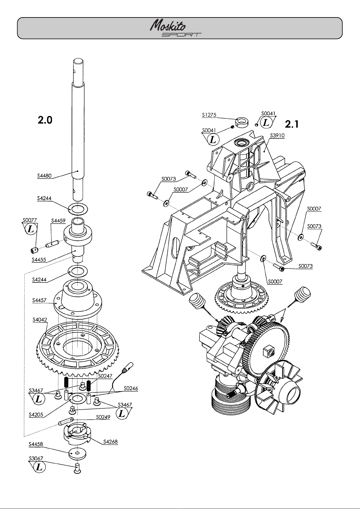
2.0 Fitting the auto-rotation
freewheel:
After you have fitted the freewheel:
CHECK THE DIRECTION OF
ROTATION! Hold the ring gear S4220
tightly; the rotor shaft should now
rotate freely in your chosen direction.
When turned in the opposite direction
the freewheel should lock.
If necessary, turn the ratchet S4268
over to correct.
2.1 Installing the rotor shaft and
gearbox assembly:
Note:
When fitting the collet ensure that
there is no axial play in the rotor shaft.
2.0 Montage de la roue libre
d‘autorotation
Après le montage de la roue libre,
EFFECTUER UN CONTROLE DU
SENS DE ROTATION !
Maintenir la couronne S4220
solidement. Le rotor doit pouvoir
tourner librement dans le sens choisi.
Contre le sens de rotation la roue libre
doit se bloquer.
Si nécessaire, inverser le cliquet
S4268.
2.1 Mise en place de l‘arbre du rotor
et de l‘unité d‘engrenage:
À noter:
À la mise en place de la bague d‘arrêt
attention au jeu axial de l‘arbre du
rotor.
15
2.0 Montage Autorotationsfreilauf:
Nach der Montage des Freilaufes;
DREHRICHTUNGSKONTROLLE !
Das Tellerrad S4220 festhalten.
Die Rotorwelle muß sich in die
gewählte Drehrichtung frei drehen
lassen.
Gegen diese Drehrichtung muß der
Freilauf sperren.
Gegebenenfalls Ratsche S4268
umdrehen.
2.1 Einbau Rotorwelle und
Getriebeinheit:
Hinweis:
Bei der Montage des Stellrings S1275
auf axiale Spielfreiheit der Rotorwelle
achten.
2.0
“R“
“L“
S0007
3.2x9x0.8
S0249
3x13.8
S0246
3 x 9.8
S4459
3x11.8
S4244
10x16x0.3
S4205
8x14x0.2
S0077
M4x5
S3467
M3x6
S3067
M3x8
S0041
M3x3
2x
1x
4x
1x
4x
1x
2x
2x
1x
1x
S0073
M3x12
4x

Baustufe / Stage / Stade: 3
16
II

Baustufe: 3 Stage: 3 Stade: 3
3.0 Assembling the fueltank
Note:
Use the thin silicone tubing for the
clunk pick-up, and the thick silicone
tubing to connect the tank to the
carburettor. An angled piece of steel
wire as shown in the sketch is a useful
tool for fitting the tank nipples.
Tip:
To cut the holes in the fueltank we
recommend using a piece of 5 mm Ø
brass tube with one end countersunk
to produce a sharp edge (see sketch).
This produces a neat hole without
burrs, and no swarf to fall into the
tank.
Caution:
The clunk weight should move freely
within the tank. It must not get stuck
against the rear inside wall of the tank.
3 Assemblage du réservoir
À noter:
Utiliser le flexible de silicone fin pour
la mise en place du plongeur du
réservoir. Le flexible épais en silicone
assure la liaison entre le réservoir et le
carburateur. Pour la mise en place
des raccords du réservoir il est
possible d‘utiliser une corde à piano
coudée.
Un conseil:
Pour réaliser les alésages du réservoir
il est possible d‘utiliser un tube de
laiton de 5 mm de à l‘intérieur (cf.
schéma). On évite ainsi les copeaux
qui risqueraient de tomber dans le
réservoir.
Attention:
Le plongeur du réservoir doit s‘y
déplacer librement sans s‘appuyer sur
la paroi arrière du réservoir.
17
3.0 Tankzusammenbau
Hinweis:
Den dünnen Silikonschlauch zur
Tankpendelmontage benutzen.
Den dicken Silikonschlauch zur
Verbindung Tank/Vergaser benutzen.
Zur Montage der Tankanschlüsse
kann ein abgewinkelter Stahldraht
benutzt werden.
Tip:
Zur Herstellung der Tankbohrungen
kann ein innen angesenktes
Messingrohr mit Ø5mm benutzt
werden (Skizze). Dadurch entsteht
kein Grat und es fallen keine Späne in
den Tank.
Achtung:
Tankpendel muß im Tank frei pendeln
können und darf nicht an der hinteren
Tankwand anliegen.

Baustufe / Stage / Stade: 4
18
II
Baustufe: 4 Stage: 4 Stade: 4
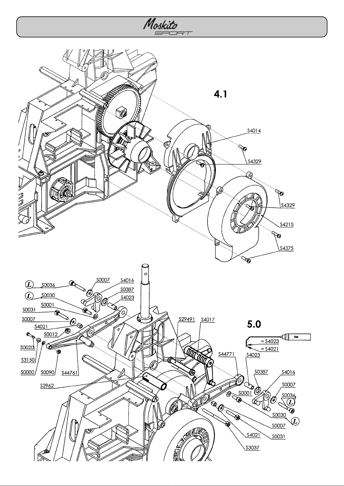
4.0 Assembling the top and bottom
chassis sections, fueltank, silencer
and/or exhaust manifold
Note:
The exhaust outlet may be on the right
side depending on the type of silencer
you are using. If you intend to fit a
tuned pipe the manifold (header)
should be installed at this stage.
The tuned pipe itself is installed during
the very last stage of assembly.
Tip:
We recommend that you connect the
fuel feed line to the carburettor now,
before the top and bottom chassis
sections are assembled, while access
is still good.
Note (sketch A):
Note that the travel „GB“ of the
bellcrank should be about 13 mm.
Select a linkage hole on the
carburettor arm which provides this,
as this arrangement provides optimum
travel adjustment for the throttle servo.
Adjust the pushrod length „GA“ to the
point where the bellcrank is at right-
angles to the chassis when the
carburettor arm is vertical.
Note:
Place front structure extension S1029
in the bottom section S4012. Drill 1.5
mm Ø holes in the bottom section for
the self-tapping screws S1005.
4.0 Assemblage de la partie
supérieure, de la partie inférieure,
du réservoir et du silencieux et du
coude-collecteur
A noter:
En fonction du silencieux utilisé, la
sortie d‘échappement peut être
orientée vers la droite.
Avec un résonateur on installe au
cours de ce stade de montage
l‘adaptateur ou le coude-collecteur
approprié au lieu du silencieux.
Le résonateur sera monté tout à la fin.
Un conseil:
Pour améliorer l‘accessibilité, il est
possible dès maintenant, avant
d‘assembler la partie inférieure et la
partie supérieure du châssis, de
raccorder déjà le branchement du
carburateur au carburateur.
À noter: (cf. schéma A)
Pour obtenir un réglage efficace de la
course du servo des gaz, il faut choisir
le point d‘asservissement du palonnier
des gaz de telle manière que la
course „GB“ du palonnier de renvoi
soit de 13 mm environ. La longueur de
la tringle „GA“ doit être réglée de telle
manière que lorsque le palonnier des
gaz se trouve à la verticale de
palonnier de renvoi forme un angle
droit avec le châssis.
À noter :
installer la rallonge de superstructure
avant S1029 dans la partie inférieure
S4012. Porter les alésages pour les
vis autotaraudeuses
S1005 à Ø 1,5 mm dans la partie
inférieure.
19
4.0 Zusammenbau Oberteil,
Unterteil, Tank und Schalldämpfer
bzw. Krümmer
Hinweis:
Je nach verwendetem Schalldämpfer
sollte die Auslaßöffnung nach rechts
zeigen. Bei Verwendung eines
Resonanzrohres wird in dieser
Baustufe anstatt des Schalldämpfers
der passende Adapter bzw. Krümmer
angeschraubt.
Das Resonanzrohr wird ganz zum
Schluß montiert.
Tip:
Aufgrund der besseren Zugänglichkeit
kann vor Zusammenbau des Chassis-
Ober- und Unterteils der
Vergaseranschlußschlauch
bereits jetzt auf den Vergaser
aufgesteckt werden.
Hinweis: (Skizze A)
Um eine optimale Wegeinstellung für
das Gasservo zu erreichen, sollte der
Anlenkpunkt amVergaserhebel so
gewählt werden, daß der Weg “GB“
des Umlenkhebels ca. 13mm beträgt.
Die Gestängelänge “GA“ ist so
einzustellen, daß bei senkrecht
stehendem Vergaserhebel der
Umlenkhebel rechtwinklig zum
Chassis steht.
Hinweis:
Vorbauverlängerung S1029 in das
Unterteil S4012 einsetzen. Die
Bohrungen für die PT-Schrauben
S1005 mit Ø 1,5 mm im Unterteil
bohren.
S0036
M3x20
S0012
M 3 STOP
S0037
M3x25
S3078
M4x10
2x
2x
2x
4x
S0001
3.2x7x0.5
4x
S1005
PT 2.5 x 6.5
2x
Baustufe / Stage / Stade: 4, 5
20
II
This manual suits for next models
1
Table of contents
Other ROBBE SCHLUTER Toy manuals


