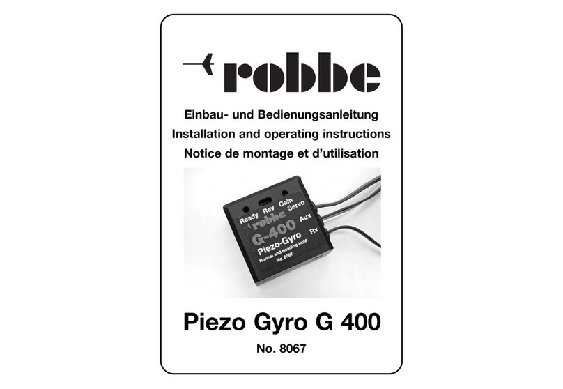
ROBBE Piezo-Gyro G 300 User manual

Einbau- und Bedienungsanleitung
Installation and operating instructions
Notice de montage et d’utilisation
Piezo Kreisel
G 300
No. 8095

No.
8095
Piezo-Kreisel G 300
2
1. Vorwort:
Der robbe Piezo-Kreisel G 300 ist ein Kreiselsystem mit Piezo - Sensor für Flug-
und Hubschraubermodelle.
Wird das Modell durch äußere Einflüsse wie Wind, schnelle Drehzahländerung
oder Pitchänderungen aus seiner Lage gebracht, so wird über den Piezo - Sensor
dieser Wert gemessen, als Steuersignal umgeformt und dem Heckrotor - Servo als
Korrekturwert zugeführt, um die Differenz auszugleichen.
Hinweis:
Um die maximale Leistung zu erreichen, soll-
te der G 300 in Verbindung mit einem sehr
schnellen Servo für die Heckrotorsteuerung
betrieben werden. Selbstverständlich können
auch Servos mit normaler Stellgeschwindig-
keit eingesetzt werden. Allerdings sind die
Stabilisierungsergebnisse dann nicht so per-
fekt wie mit den superschnellen Servos.
Servoempfehlung:
Betrieb mit 4,8 Volt (4 NC)
Servo S 9203 Bestell - Nr. F 1264
Betrieb mit 6 Volt (5 NC)
Servo S 9402 Bestell - Nr. F 1253
2. Für ganz eilige, Kurzanleitung zur ersten
Inbetriebnahme:
· Anschluß gemäß Skizze 1 vornehmen
· Sender einschalten, Empfänger einschalten
· Modell bzw. Piezo-Kreisel G 300 ca. 10 Sekunden
nicht bewegen, Piezo-Kreisel G 300 führt seinen
Nullabgleich durch.
· Abgleich fertig -> Heckrotor - Servo läuft auf
Ausgangsstellung und die rote LED ”Ready“ am Piezo-
Kreisel G 300 leuchtet.
· Schieberegler Kanal 5 in Mittelstellung bringen (mittle-
re Empfindlichkeit).
- Regelrichtung überprüfen, ggf. Reverse-Schalter
„REV“ betätigen. Durch erneutes Einschalten
nochmals den Abgleich durchführen.
1
2
3
4
5
6
7
8
Receiver
35 MHz
Heckrotorkanal (robbe Futaba = Kan. 4
Kan. 5
freier Zusatzkanal
Skizze 1
LINEAR
Skizze 2
0 %
100 %
Empfindlichkeit

Piezo-Kreisel G 300 No.
8095
3
ReadyRevGain
Servo
Aux
Rx
3D
GYRO
ReadyRevGain
Servo
Aux
Rx
3D
GYRO
Ready Rev Gain
Servo
Aux
Rx
3D
GYRO
Stabilisierung der Hochachse
Stabilisierung der Längsachse
Stabilisierung der Querachse
Skizze 3
3. Einbau
Wichtig: Alle Kreiselsysteme mit Piezo - Sensoren sind empfindlich gegen
Vibrationen. In einem vibrationsbelasteten Modell werden Sie mit keinem Piezo -
Kreisel zufriedenstellende Ergebnisse erzielen. Mit den beiliegenden
Schaumstoffteilen können Sie das Kreiselsystem auf Ihr Modell anpassen. Gute
Ergebnisse wurden auch mit dem 3,2 mm dicken Doppelklebeband von 3M (robbe
Bestell - Nr. 5014) erzielt. Deshalb empfehlen wir Ihnen dringend, diesem Punkt
besondere Aufmerksamkeit zu schenken.
Kleben Sie einen der mitgelieferten selbstklebenden Schaumstoffstreifen auf die
Unterseite des Kreisel - Gehäuses. Plazieren Sie das Gehäuse nun an einer
vibrationsarmen Stelle im Modell (beim Futura z.B. im Dom unter dem
Pitchservo). Der Kreisel ist so einzubauen, daß die zu stabilisierende Achse senk-
recht durch den Kreisel verläuft ( siehe Skizze 3). Die Einbauposition ist unkritisch,
ob in der Nähe der Rotorwelle oder am Servovorbau, wichtig ist nur, daß der
Piezo-Kreisel G 300 gegen Vibrationen gut geschützt ist.

No.
8095
Piezo-Kreisel G 300
4
4. Anschluß und Inbetriebnahme
Hinweis: Sobald der Aux-Kanal angeschlossen wird, ist der Regler Gain außer
Funktion.
4.1. Anschluß und Abstimmung des Piezo-Kreisel G 300 mit
Empfindlichkeitseinstellung vom Sender aus
Wichtig:
· Der Piezo-Kreisel G 300 erkennt und korrigiert kleinste Abweichungen, so
daß er keine Unterstützung durch einen Pitch -> Heckrotor Mischer (Revo-
Mix) benötigt, wir empfehlen diesen Mischer auszuschalten.
· Um schnelle Pirouetten zu steuern, wurde bei herkömmlichen
Kreiselsystemen die Empfindlichkeit elektronisch ausgeblendet (Gyro-Sens-
Mischer). Dies ist bei dem Piezo-Kreisel G 300 nicht mehr erforderlich, denn
hier wird das Sensorsignal vom Steuerknüppel übersteuert. Wie stark es
übersteuert wird, legt man über die Servowegreduzierung (ATV) fest.
Deshalb muß der Ausblendmischer (Gyro-Sens) unbedingt ausgeschaltet
werden.
· Ebenfalls sind alle anderen Mischfunktionen die auf den Heckrotor wirken
abzuschalten (z.B. Mischer Taumelscheibe -> Heckrotor)
Wie in der Skizze 1 gezeigt, den Piezo-Kreisel G 300 zwischen das
Heckrotorservo und den Empfänger stecken und den Anschluß „Aux“ an einen
freien Schieberkanal (z.B. Kanal 5) anschließen.
· Sender einschalten.
· Empfänger einschalten.
· Modell bzw. Piezo-Kreisel G 300 ca. 10 Sekunden nicht bewegen, Piezo-
Kreisel G 300 führt Nullabgleich durch.
·Abgleich fertig -> Heckrotorservo läuft auf Ausgangsstellung und die rote
LED ”Ready“ am Piezo-Kreisel G 300 leuchtet.
· Sollte das Modell trotzdem bewegt worden sein, oder die Kontroll - LED blin-
ken, so muß zur erneuten Initialisierung die Empfängerstromversorgung aus
- und wieder eingeschaltet werden.
· Mit Schieberegler Kanal 5 maximale Empfindlichkeit einstellen (keine
Pendelbewegung am Heck).
· Heckrotortrimmung in die Mitte stellen.

Piezo-Kreisel G 300 No.
8095
5
· Servohebel mechanisch so anbringen, daß der Arm nahezu 90° zum
Gestänge steht.
· Gestänge am Heckgetriebe in das äußerste Loch einhängen.
· Heckrotor Steuerknüppel auf Vollausschlag stellen.
· Gestänge am Servohorn so einhängen, daß sich der maximale Steuerweg
ergibt aber kein mechanischer Anschlag am Heckrotor erfolgt.
· Kontrolle der Servo Laufrichtung: Heckrotor Steuerknüppel nach rechts
bewegen, gehen die Vorderkanten der Heckrotorblätter nach links? Wenn
nicht, Servo Reverse am Sender durchführen.
· Kontrolle Wirkrichtung Kreisel (Schalter REV) : Heckausleger nach rechts
bewegen, gehen die Vorderkanten der Heckrotorblätter nach links? Wenn
nicht, den Schalter „REV“ am Piezo-Kreisel G 300 umschalten.
Hinweis: Umschaltung erfolgt erst nach erneutem Aus- Einschalten des
Kreisel (Angaben in Flugrichtung).
Nun kann über den Schieberegler 5, vom Sender aus die Empfindlichkeit stufen-
los von 0 - 100 % eingestellt werden.
Hinweis:
Im Gegensatz zu den bisherigen Kreiselsystemen wird beim Piezo-Kreisel G 300
mit der Kreiselempfindlichkeit auch der Servoweg reduziert, da bei geringerer
Kreiselempfindlichkeit auch ein kleinerer Heckrotorsteuerweg (bei gleicher
Steuerfolgsamkeit) benötigt wird.
Der Kreisel besitzt zudem eine exponentielle Steuercharakteristik. Eine
Einstellung von unter 30 % ist nicht praxisgerecht und sollte nicht vorgenommen
werden, weil sich der Heckrotorsteuerweg deutlich reduziert.
Um sich beim 1. Flug an den Kreisel zu gewöhnen, empfehlen wir folgende
Grundeinstellwerte:
· Servowegeinstellung Heckrotor (ATV) : ca. 70 %
· Kreiselempfindlichkeit (ATV): ca. 70 %
4.2. Anschluß des Piezo-Kreisel G 300 mit manueller Empfindlichkeitsein-
stellung am Kreisel.
Bei Fernsteueranlagen mit geringer Kanalzahl, steht häufig kein freier Kanal zur
Einstellung der Kreiselempfindlichkeit zur Verfügung. In diesem Falle den

No.
8095
Piezo-Kreisel G 300
6
Anschluß „Aux“ des Kreisels nicht anschließen. Nun kann über den im Kreisel
befindlichen Regler ”Gain“ die Empfindlichkeit stufenlos von 0 - 100 % eingestellt
werden, wobei im Uhrzeigersinn die Empfindlichkeit erhöht und entgegengesetzt
verringert wird.
Hinweis:
Im Gegensatz zu den bisherigen Kreiselsystemen wird beim Piezo-Kreisel G 300
mit der Kreiselempfindlichkeit auch der Servoweg reduziert, da bei geringerer
Kreiselempfindlichkeit auch ein kleinerer Heckrotorsteuerweg (bei gleicher
Steuerfolgsamkeit) benötigt wird.
Der Kreisel besitzt zudem eine exponentielle Steuercharakteristik. Eine
Einstellung von unter 30 % ist nicht praxisgerecht und sollte nicht vorgenommen
werden, weil sich der Heckrotorsteuerweg deutlich reduziert.
Wie in der Skizze 1 gezeigt den Piezo-Kreisel G 300 zwischen das Heckrotorservo
und den Empfänger stecken. Der Anschlußstecker „Aux“ bleibt in dieser
Anschlußvariante frei.
5. Allgemeines
5.1 Modellvoraussetzungen
Durch die hohe Empfindlichkeit des Kreisels und das starke, schnell reagierende
Heckrotorservo und der damit verbundenen Reaktion des Heckrotors, wird das
Heck deutlich mehr als üblich belastet.
Dies erfordert einen torsionssteifen Heckrotorantrieb und ein standfestes
Heckrotorgetriebe. Es wird ein Starrantrieb empfohlen, um die höheren
Lastwechselreaktionen abzufangen. Des weiteren muß die Gestängeverbindung
so spielarm und leichtgängig wie möglich sein.
5.2 Temperaturanpassung
Obwohl das Kreiselsystem nach besten technischen Möglichkeiten temperatur-
kompensiert wurde, ist bei Temperaturdifferenzen zwischen Kreisel und
Umgebung, eine Anpassung erforderlich.
Hierzu wird empfohlen, den Kreisel in eingeschaltetem Zustand bis ca. 5 Minuten
an die Umgebungstemperatur anzupassen. Danach erneut aus - und einschalten.

Piezo-Kreisel G 300 No.
8095
7
5.3 Sonstige Hinweise:
· Bei RC-Anlagen mit flugzustandsabhängiger ATV- Einstellung, z.B. FC 28
kann für jeden Flugzustand eine separate Heckrotor - Servoweg-(ATV) und
Empfindlichkeitseinstellung vorgenommen werden, welche über die Flug-
zustandsschalter „Idle-Up 1“, „Idle-Up 2“ automatisch mit umgeschaltet wird.
· Je nachdem, welche Haupt- und Heckrotorkombination verwendet wird, kann
es dazu führen, daß der Heckausleger leicht schwingt. Dies ist nicht unbe-
dingt auf eine zu hohe Empfindlichkeitseinstellung zurückzuführen, sondern
kann auch von zu großen oder zu tiefen Heckrotorblättern herrühren. In die-
sem Fall die Heckrotorblätter ca. 3 - 5mm kürzen.
· Die beim Einschalten des Kreisels eingelesene Konfiguration der Kanäle
Heckrotor und Aux sowie die Position des Rev-Schalters werden abgespei-
chert. Sofern die Stecker ”Aux“ bzw. ”Rx“ im Empfänger umgesteckt werden
oder die Reversefunktion geändert wird, ist es erforderlich den Kreisel aus -
und einzuschalten damit die Konfiguration neu eingelesen und abgespeichert
wird.
6. Technische Daten:
Betriebsspannung: 3 - 8 Volt aus dem Empfängerakku
Stromaufnahme: ca. 25 mA (bei 4,8V)
Abmessungen: ca. 41 x 41 x 20 mm
Gewicht: ca. 30 g
7. Lieferumfang
Piezo-Kreisel G 300
Selbstklebende Dämpfungsschaumstoffstreifen
Bedienungsanleitung
robbe Modellsport GmbH & Co. KG
Technische Änderungen vorbehalten

No.
8095
Piezo-Kreisel G 300
8
1. Foreword:
The robbe Piezo-Gyro G 300 is a gyro system based on a piezo sensor, and is sui-
table for fixed-wing model aircraft and helicopters.
If an external influence such as a gust of wind, or a rapid change in rotational
speed or collective pitch pushes the model out of its intended position, then the
piezo-sensor picks up and measures the change, converts it into a compensatory
signal and passes it to the tail rotor servo
which then carries out the necessary cor-
rective action.
Note:
If you wish to achieve maximum perfor-
mance the Piezo-Gyro G 300 should
always be operated in conjunction with a
very fast tail rotor servo. Of course, servos
of normal transit speed can still be used,
but the stabilisation effect will not be quite
as perfect as with a super-fast servo.
Recommended servos:
4.8 Volt power supply (4 NC)
S 9203 servo Order No. F 1264
6 Volt power supply (5 NC)
S 9402 servo Order No. F 1253
2. If you are in a real hurry, here are
brief instructions for getting the gyro
working:
- Connect the system as shown in Sketch 1
- Switch on the transmitter, switch on the receiver
- Do not touch the model or Piezo-Gyro G 300 for
about 10 seconds while the Piezo-Gyro G 300 car-
ries out its zero calibration procedure.
-When ready -> tail rotor servo runs to starting posi-
tion and the red „Ready“ LED on the Piezo-Gyro G
300 lights up.
- Move channel 5 slider to centre (50% gyro Gain con-
trol).
- Check the direction of operation of the gyro and ope-
rate the reverse switch „REV“ if necessary. Switch
off, then on again and check the result.
1
2
3
4
5
6
7
8
Receiver
35 MHz
LINEAR
Sketch 1
Tail rotor channel
(robbe-Futaba = Ch. 4)
Ch. 5 Vacant
auxiliary channel
100 %
0 %
Sketch 2
Gyro Gain

Piezo-Kreisel G 300 No.
8095
9
3. Installation
Important: all gyro systems based on piezo sensors are vulnerable to vibration,
and if your model suffers from excessive vibration you will not obtain satisfactory
results with any piezo-gyro. However, you can be sure of obtaining good results
by mounting the gyro unit in your model using the foam plastic damper pads sup-
plied. We also recommend the 3.2 mm thick double-sided foam tape made by 3M
(robbe Order No. 5014). To avoid disappointment we strongly recommend that you
pay particular attention to the elimination of vibration in your model.
Apply one of the self-adhesive foam strips to the underside of the gyro case. Install
the case in a low-vibration location in the model (e.g. in the dome under the
collective pitch servo of a Futura). The gyro must be orientated in such a way that
the axis to be stabilised runs vertically through the gyro (see Sketch 3). The instal-
lation position is non-critical, and can be close to the rotor shaft or in the front
servo structure. The only really important point is that the Piezo-Gyro G 300 is well
protected from vibration.
ReadyRevGain
Servo
Aux
Rx
3D
GYRO
ReadyRevGain
Servo
Aux
Rx
3D
GYRO
Ready Rev Gain
Servo
Aux
Rx
3D
GYRO
Sketch 3 Stabilisation of the vertical axis
Stabilisation of the longit. axis
Stabilisation of the lateral axis

No.
8095
Piezo-Kreisel G 300
10
4. Connecting the gyro system, using the system for the first time
Note: the manual „gain“ adjustor is switched out of circuit if you connect the Aux
channel to the receiver.
4.1 Connecting the Piezo-Gyro G 300 and setting it up with gyro gain control
from the transmitter
Important:
- The Piezo-Gyro G 300 detects and corrects the tiniest of deviations, which
means that it does not require assistance from a collective pitch -> tail rotor
mixer (Revo-Mix). We recommend that you switch this mixer off.
- Conventional gyro systems usually feature electronic gyro suppression
(Gyro-Sens.-Mixer) which allows the model to fly high-speed pirouettes. This
is not required with the Piezo-Gyro G 300, since the sensor signal is always
over-ridden by any stick command. The extent to which it is over-ridden is
determined by the servo travel setting (ATV). For this reason the suppressi-
on mixer (Gyro-Sens.) must always be switched out of circuit when the Piezo-
Gyro G 300 is in use.
- For the same reasons all the other mixer functions which affect the tail rotor
(e.g. swashplate -> tail rotor mixer) should also be switched off.
Connect the Piezo-Gyro G 300 between the tail rotor servo and the receiver as
shown in Sketch 1, and connect the „Aux“ connector to a vacant slider channel
(e.g. Channel 5).
- Switch on the transmitter.
- Switch on the receiver.
- Leave the model and the Piezo-Gyro G 300 untouched for about 10
seconds while the Piezo-Gyro G 300 carries out its zero calibration process.
- Process complete -> tail rotor servo runs to starting position, red „Ready“
LED on Piezo-Gyro G 300 lights up.
- If you move the model too soon, or the monitor LED flashes, you must re-
initialise the gyro by switching the receiver power supply off and then on
again.
- Move the channel 5 slider to max. gyro gain control (no tail oscillation).
- Set the tail rotor trim to centre.

Piezo-Kreisel G 300 No.
8095
11
- Fit the output arm on the tail rotor servo in such a way that the arm is exact-
ly at 90° to the pushrod (or as close as possible to 90°).
- Connect the pushrod to the outermost hole at the tail rotor gearbox.
- Move the tail rotor stick to full travel.
- Connect the pushrod to one of the outer holes in the servo output arm. Aim
for maximum linear pushrod movement, with the proviso that the linkage
must not stall the servo (mechanical obstruction) at full travel.
- Check the direction of servo travel. Move the tail rotor stick to the right and
watch the tail rotor:
- The leading edge of the tail rotor blades should now move to the left; if not,
reverse the tail rotor servo at the transmitter.
- Check the direction of operation of the gyro (REV switch). Swing the tail
boom to the right: the leading edge of the tail rotor blades should now move
to the left. If not, operate the „REV“ switch on the Piezo-Gyro G 300. Note:
if you use the „REV“ switch on the gyro the change will not take effect until
you switch the gyro off and then on again. All stated directions are as seen
from the tail of the model looking forward.
You can now adjust the sensitivity (gain) of the gyro from the transmitter. Slider 5
provides proportional control over the range 0 - 100%.
Note:
in contrast to previous gyro systems, any reduction in the gain of the Piezo-Gyro
G 300 simultaneously reduces servo travel, since lower gyro sensitivity calls for
less tail rotor travel in order to obtain the same control response.
The gyro also features an exponential control characteristic curve. Values below
30% are not of practical usefulness and should not be set in any case because
they would reduce the tail rotor control travel to a dangerous extent.
For initial familiarisation flights with the new gyro we suggest the following
basic settings:
Tail rotor servo travel (ATV) approx. 70%
Gyro gain (ATV): approx. 70%
4.2 Connecting the Piezo-Gyro G 300 with manual gain adjustment on the
gyro
If your radio control system has relatively few channels you may well find that no

No.
8095
Piezo-Kreisel G 300
12
vacant channel is available for remote gyro gain adjustment. If this is the case sim-
ply leave the „Aux“ connector (attached to the gyro) unconnected. Gyro sensitivi-
ty can now be adjusted proportionally within the range 0 - 100 % by rotating the
adjustor marked „Gain“ on the gyro. Turn it clockwise to increase gain, and anti-
clockwise to reduce it.
Note:
In contrast to previous gyro systems, any reduction in the gain of the Piezo-Gyro
G 300 simultaneously reduces servo travel, since lower gyro sensitivity calls for
less tail rotor travel in order to obtain the same control response.
The gyro also features an exponential control characteristic curve. Values below
30% are not of practical usefulness and should not be set in any case because
they would reduce the tail rotor control travel to a dangerous extent.
Connect the Piezo-Gyro G 300 between the tail rotor servo and the receiver as
shown in Sketch 1. In this variant the connector marked „Aux“ is not connected.
5. General information
5.1 Model requirements
The high sensitivity of the gyro, the powerful response of the tail rotor and the high
speed with which the tail rotor reacts combine to place much higher loads than
usual on the tail of the model helicopter.
This in turn requires a torsionally rigid tail rotor drive system and a strong tail rotor
gearbox. We recommend rigid drive systems, as they are better able to absorb the
forces exerted by the rapid changes in load. The mechanical linkage to the tail
rotor must also be as free-moving and direct (minimum slop) as possible.
5.2 Temperature adjustment
Although the gyro system is temperature-compensated as far as possible using
the currently available solutions, it is still necessary for the gyro to be allowed to
adjust itself to the ambient temperature.
For best results we recommend that you leave the gyro switched on for about 5
minutes at the start of a flying session so that it can adjust to the surrounding tem-
perature. After this period switch the system off and then on again.

Piezo-Kreisel G 300 No.
8095
13
5.3 Supplementary notes
- If you are using an RC system with flight mode dependentATV, e.g. an FC 28,
you can set tail rotor servo travel (ATV) and gyro gain separately for each flight
mode, and these settings can then be called up automatically when you ope-
rate the flight mode switches „Idle-Up 1“ and „Idle-Up 2“.
- Depending on the combination of main and tail rotor you are using, you may
find that the tail boom oscillates (swings from side to side) slightly. This may
be due to an excessively high gyro gain setting, but it can also be the result of
tail rotor blades which are too long or too wide. In this case the solution is to
shorten the tail rotor blades by about 3 - 5 mm.
- When the gyro is switched on it detects and stores the configuration of the tail
rotor and Aux channels and the position of the REV switch. If you ever need
to connect the „Aux“ and „Rx“ plugs to different receiver sockets, or if you use
the reverse function, it is then necessary to switch the gyro off and on again
so that it can read in the new configuration and store it.
6. Specification:
Operating voltage: 3 - 8 Volts, from receiver battery
Current drain: approx. 25 mA (at 4.8 V)
Dimensions: approx. 41 x 41 x 20 mm
Weight: approx. 30 g
7. Contents of set
Piezo-Gyro G 300
self-adhesive strips of damping foam
operating instructions
robbe Modellsport GmbH & Co. KG
We reserve the right to alter technical specifications

No.
8095
Piezo-Kreisel G 300
14
1.Préface:
Le gyroscope robbe G 300 est un système gyroscopique pour le pilotage de
modèles réduits d’avions, de planeurs et d’hélicoptères avec capteur piézo.
Lorsque le modèle est tiré de son assiette de vol par des incidences externes tel-
les que le vent, une modification rapide du régime ou des changements de pas, le
capteur piézo mesure cette valeur, la transforme en signal et la communique au
servo du rotor arrière comme valeur correctrice, afin de compenser la différence
apparue.
À noter:
pour atteindre sa puissance maximale, il faut
que le gyroscope G 300 soit associé à un
servo extrêmement rapide pour le rotor arrière.
Il est naturellement possible de l’exploiter
également avec des servos à vitesse de posi-
tionnement normale. Toutefois les effets de
stabilisation ne seront alors pas aussi rapides
qu’avec un servo super rapide.
Servos recommandés:
alimenté par 4,8 volts (4 éléments Cd-Ni)
servo S 9203 réf. F 1264
alimenté par 6 volts (5 éléments Cd-Ni)
Servo S 9402 réf. F 1253
2. Notice abrégée pour les pilotes très pres-
sés avant la première mise en service:
- réaliser le raccordement selon les indicati-
ons du schéma 1
- mettre l’émetteur et le récepteur en marche
- ne pas déplacer le modèle ni le gyroscope G 300 pen-
dant approx. 10 secondes, le gyroscope G 300 réalise
un calibrage à zéro
- calibrage achevé -> le servo du rotor arrière se dépla-
ce en position initiale et la LED rouge „Ready“ du gyros-
cope G 300 s’allume
- amener le curseur de la voie 5 en position médiane
(50 % sensibilité).
- Contrôler le sens de la régulation, si nécessaire,
actionner le commutateur-inverseur „REV“. Remettre
en marche et effectuer un nouvel équilibrage.
1
2
3
4
5
6
7
8
Receiver
35 MHz
LINEAR
voie du rotor arrière
robbe-Futaba = voie 4
voie 5, auxi-
liaire
schéma 1
100 %
schéma 2 0 %
sensibilité

Piezo-Kreisel G 300 No.
8095
15
3.Mise en place
Important: tous les systèmes gyroscopiques à capteur piézo sont très sensibles
aux vibrations. Aucun gyroscope piézo ne donnera de bons résultats dans un
modèle dont les charges vibratoires sont élevées. Si nécessaire, tester également
son implantation avec d’autres types de mousse plastique. De bons résultats ont
également été obtenus avec le double face de 3,2 mm d’épaisseur de la Sté 3M
(robbe réf. 5014). Nous vous prions donc instamment d’accorder un attention très
particulière à ce point.
Coller un morceau de mousse plastique autocollante fournie avec l’appareil sur le
fond du carter du gyroscope. Disposer ensuite le carter à un endroit à faibles
vibrations dans le modèle (dans le modèle par ex. dans la coupole sous le servo
de pas). Installer le gyroscope de sorte que l’axe qu’il est susceptible de stabiliser
le traverse verticalement ( cf. schéma 3). La position d’implantation n’est pas cri-
tique, qu’elle soit proche de l’arbre du rotor ou de la superstructure avant qui porte
les servos, cela n’a guère d’importance, par contre il est essentiel que le gyros-
cope soit protégé des vibrations.
ReadyRevGain
Servo
Aux
Rx
3D
GYRO
ReadyRevGain
Servo
Aux
Rx
3D
GYRO
Ready Rev Gain
Servo
Aux
Rx
3D
GYRO
Stabilisation de l’axe vertical
Stabilisation de l’axe de lacet
Stabilisation de l’axe transvers.
schéma 3

No.
8095
Piezo-Kreisel G 300
4. Branchement et mise en service
À noter: dès que la voie Aux est raccordée, le variateur Gain est hors fonction.
4.1. Branchement du gyroscope G 300 avec réglage de la sensibilité à partir
de l’émetteur
Important:
- Le gyroscope G 300 détecte et corrige les moindres écarts de telle sorte qu’il
n’exige pas de mixage de soutien pas -> rotor arrière (Revo-Mix), nous
recommandons de couper ce mixage.
- Pour piloter des pirouettes rapides, avec les systèmes gyroscopiques com-
muns leur sensibilité était discriminée (mixage Gyro-Sens). Ceci n’est plus
nécessaire avec le gyroscope G 300, car avec lui, le signal du capteur est
simplement surmodulé par le manche. L’importance de cette surmodulation
est déterminée par le réglage de la réduction de la course du servo (ATV).
Voilà pourquoi il faut absolument couper le mixage de discrimination (Gyro-
Sens).
- Il faut également couper toutes les autres fonctions de mixage qui présentent
un effet sur le rotor arrière (par ex. mixage plateau cyclique -> rotor arrière)
Comme indiqué sur le schéma 1, installer le gyroscope G 300 entre le servo de
rotor arrière et le récepteur et raccorder le connecteur „AUX“ à une voie à curseur
libre ( voie 5 ).
- Mettre l’émetteur en marche
- mettre le récepteur en marche
- ne pas bouger le modèle ni le gyroscope G 300 pendant approx. 10 secon-
des, le gyroscope G 300 effectue son étalonnage à zéro
- calibrage achevé -> le servo de rotor arrière se déplace en position initiale
et la LED rouge du gyroscope G 300 s’allume
- si le modèle a malgré tout bougé pour une raison ou pour une autre ou lors-
que la LED clignote, il faut refaire une initialisation en coupant l’alimentation
du récepteur puis en la rétablissant
- amener le curseur de la voie 5 dans la position sensibilité max. (pas de mou-
vement pendulaire de l’arrière).
- disposer le trim du rotor arrière en position médiane
16

Piezo-Kreisel G 300 No.
8095
17
- disposer le manche du servo mécaniquement de manière à ce qu’il présen-
te un angle de 90° pratiquement par rapport à la tringle
- accrocher la tringle au mécanisme du rotor arrière dans le trou le plus à l’ex-
térieur
- disposer le manche du rotor arrière en position de débattement maximum
- accrocher la tringle au guignol du servo de manière à obtenir la course la plus
longue sans butée mécanique contre le rotor arrière
- contrôle du sens de rotation des servos: déplacer le manche de commande
du rotor arrière vers la droite l’arête avant des pales du rotor arrière va vers
la gauche? Si ce n’est pas le cas, inverser la course du servo au niveau de
l’émetteur
- contrôle de la direction de l’effet du gyroscope (commutateur REV) : dépla-
cer la flèche vers la droite, l’arête avant des pales du rotor arrière va vers la
gauche? Si ce n’est pas le cas, commuter le commutateur „REV“ sur le
gyroscope G 300. À noter : la commutation ne devient efficace qu’après avoir
coupé puis rétabli le gyroscope
Il est dès lors possible avec le curseur 5, à partir de l’émetteur, de régler la sensi-
bilité progressivement de 0 - 100 %.
À noter: contrairement à ce qui se passait pour les systèmes gyroscopiques com-
muns jusqu’à présent, avec le gyroscope G 300 la course du servo est aussi rédui-
te avec la sensibilité du gyroscope, car, lorsque la sensibilité du gyroscope est
réduite il suffit d’une plus petite course du rotor arrière bien que la capacité d’exé-
cution des instructions reste la même.
Par ailleurs, le gyroscope dispose d’une caractéristique de pilotage exponentielle.
Un réglage inférieur à 30 % n’est pas approprié à la pratique et ne doit pas être
programmé car la course de pilotage du rotor arrière est considérablement rédui-
te.
Pour se familiariser avec le gyroscope lors du premier vol, nous recom-
mandons les réglages initiaux suivants:
réglage de la course du servo du rotor arrière (ATV) : approx. 70 %
sensibilité du gyroscope (ATV): approx. 70 %
4.2. Raccordement du gyroscope G 300 avec réglage manuel de la sensibi-
lité sur le gyroscope.
Sur les ensembles de radiocommande disposant de peu de voies, il ne reste sou-

No.
8095
Piezo-Kreisel G 300
18
vent pas de voie disponible pour le réglage de la sensibilité du gyroscope. Dans
ce cas, ne pas raccorder le connecteur „Aux“ du gyroscope. Il est alors possible
de régler sur le gyroscope la sensibilité progressivement de 0 - 100 %, la sensibi-
lité augmentant si on tourne dans le sens des aiguilles d’une montre et diminuant
dans le sens opposé.
À noter:
contrairement à ce qui se passait pour les systèmes gyroscopiques communs jus-
qu’à présent, avec le gyroscope G 300 la course du servo est aussi réduite avec
la sensibilité du gyroscope, car, lorsque la sensibilité du gyroscope est réduite il
suffit d’une plus petite course du rotor arrière bien que la capacité d’exécution des
instructions reste la même.
Par ailleurs, le gyroscope dispose d’une caractéristique de pilotage exponentielle.
Un réglage inférieur à 30 % n’est pas approprié à la pratique et ne doit pas être
programmé car la course de pilotage du rotor arrière est considérablement rédui-
te.
Comme indiqué sur le schéma 1, installer le gyroscope G 300 entre le servo du
rotor arrière et le récepteur. Dans cette variante, le connecteur de raccordement
„Aux“ reste non affecté.
5. Généralités
5.1 Condition préalables imposées au modèles
Étant donné la haute sensibilité du gyroscope et la force et la rapidité de réaction
du servo de rotor arrière et donc la réaction proportionnelle du rotor arrière, les
efforts imposés à la flèche sont nettement supérieurs aux charges habituelles.
Ceci exige un entraînement du rotor arrière insensible aux efforts de torsion et un
mécanisme de rotor arrière particulièrement solide. Une transmission rigide est de
ce fait recommandée pour absorber les réactions de transfert de charge très
importantes. Par ailleurs, la tringle de liaison doit être absolument absente de jeu
et particulièrement souple.
5.2 Adaptation thermique
Bien que le système gyroscopique ait été pourvu d’un dispositif de compensation
de la température bénéficiant des recherches techniques les plus récentes, une
adaptation s’impose en présence de nuances de température entre la températu-
re du gyroscope et la température ambiante.

Piezo-Kreisel G 300 No.
8095
19
Voilà pourquoi il est recommandé de laisser le gyroscope sous tension 5 minutes
environ afin qu’il s’adapte à la température ambiante. Le couper ensuite puis le
remettre sous tension.
5.3 Autres remarques :
sur les ensembles de radiocommande dont le réglage ATV est fonction de la
phase de vol, par exemple l’ensemble FC 28, il est possible, pour chaque phase
de vol, de définir une course autonome du servo du rotor arrière (ATV) et un sen-
sibilité particulière également qu’il est possible de requérir automatiquement et
simultanément à l’aide des commutateurs de phase de vol „Idle-Up 1“, „Idle-Up 2“.
En fonction de la combinaison rotor principal/rotor arrière, il peut se produire que
la flèche oscille légèrement. Cette réaction n’est pas obligatoirement causée par
une sensibilité trop élevée, mais peut également être provoquée par des pales de
rotor arrière trop grandes ou dont la corde est trop importante. Dans ce cas, rac-
courcir les pales du rotor arrière de 3 à 5 mm.
La configuration des voies rotor arrière et Aux, de même que la position du com-
mutateur Rev (inversion de la course de servo) sont lues lorsque le gyroscope est
mis en marche puis sauvegardées. Si l’ordre d’affectation des voies „Aux“ ou „Rx“
est modifié sur le récepteur ou si la fonction d’inversion est actionnée, il faut cou-
per puis remettre le gyroscope sous tension afin que la configuration soit saisie
puis mise en mémoire.
6. Caractéristiques techniques :
tension de service: 3 - 8 volts fournis par l’accu du récepteur
consommation: approx. 25 mA (à 4,8V)
encombrement: approx. 41 x 41 x 20 mm
poids: approx. 30 g
7. Contenu du kit
gyroscope G 300
morceaux de mousse plastique autocollants d’amortissement
mode d’emploi
robbe Modellsport GmbH & Co. KG
Sous réserve de modification technique

Irrtum und technische Änderungen vorbehalten. Für Druckfehler wird keine Haftung
übernommen.
Kopie oder Nachdruck, auch auszugsweise nur mit schriftlicher Genehmigung der Fa.
robbe Modellsport GmbH & Co. KG
E.&O.E. We reserve the right to alter technical specifications. We accept no liability for
printing errors.
This text may not be copied or reproduced in any form, in whole or in part, without the
prior written authorisation of robbe Modellsport GmbH & Co. KG
Sous réserve d’erreur et de modification technique. Sous réserve de fautes d’impressi-
on.
Reproduction complète ou partielle interdite sans autorisation écrite de robbe
Modellsport GmbH & Co. KG
robbe Modellsport GmbH & Co. KG
Metzloserstr. 36
Telefon 06644 / 870
36355 Grebenhain robbe Form 40-4419 BAJI
Table of contents
Languages:
Other ROBBE Science Education Product manuals
