Robe CitySkape Xtreme User manual

Version 2.2

CitySkape Xtreme (RGBW)
2
Table of contents
1. Safety instructions ...................................................................................................................................................... 3
2. Fi ture e terior view ................................................................................................................................................... 4
3. Installation .................................................................................................................................................................. 5
3.1 Rigging the fi ture ................................................................................................................................................. 5
3.2 Connection to the mains ...................................................................................................................................... 6
3.3 Installation of the barn-doors, top/half top hats ................................................................................................. 7
3.4 Changing the beam angle ..................................................................................................................................... 7
3.5 DMX 512 connection ............................................................................................................................................ 8
3.6 Master/slave connection ...................................................................................................................................... 8
3.6 Stand-alone operation .......................................................................................................................................... 8
4. CitySkape Xtreme (RGBCW) - DMX protocol ............................................................................................................ 10
5. Control menu map .................................................................................................................................................... 12
6. Fi ture menu ............................................................................................................................................................. 14
6.1 Fi ture Address ................................................................................................................................................... 15
6.2 Fi ture information ............................................................................................................................................. 15
6.3 Personality .......................................................................................................................................................... 16
6.4 Manual mode ...................................................................................................................................................... 17
6. 5 Test sequences................................................................................................................................................... 17
6.6 Stand-alone setting ............................................................................................................................................. 17
6.7 Special functions ................................................................................................................................................. 18
7. RDM .......................................................................................................................................................................... 20
8. Error and information messages .............................................................................................................................. 21
9. Wireless DMX operation ........................................................................................................................................... 21
10. Technical specifications .......................................................................................................................................... 21
11. Cleaning and maintenance ..................................................................................................................................... 24

CitySkape Xtreme (RGBW)
3
FOR YOUR OWN SAFETY, PLEASE READ THIS USER MANUAL CAREFULLY
BEFORE POWERING OR INSTALLING YOUR CITYSKAPE XTREME !
Save it f r future reference.
This device has left our premises in absolutely perfect condition. In order to maintain this condition and to ensure a
safe operation, it is absolutely necessary for the user to follow the safety instructions and warning notes written in
this manual.
The manufacturer will not accept liability for any resulting damages caused by the non-observance of this manual
or any unauthorized modification to the device.
Please consider that damages caused by manual modifications to the device are not subject to warranty.
1. Safety instructions
DANGEROUS VOLTAGE CONSTITUTING A RISK OF ELECTRIC SHOCK IS PRESENT WITHIN THIS UNIT!
Make sure that the available voltage is not higher than stated on the rear panel of the fi ture.
This fi ture should be operated only from the type of power source indicated on the marking label. If you are not
sure of the type of power supplied, consult your authorized distributor or local power company.
Always disconnect the fi ture from AC power before cleaning, removing or installing the fuses, or any part.
Do not overload wall outlets and e tension cords as this can result in fire or electric shock.
Make sure that the power/data cord is never crimped or damaged by sharp edges. Check the fi ture and the
power/data cord from time to time.
Do not install the unit near naked flames.
During the operation the housing becomes hot (up to 85°C)
Refer servicing to qualified service personnel.
This fixture falls under protection class I. Therefore this fixture has to be connected to a mains socket outlet with
a protective earthing connection.
Do not connect this fi ture to a dimmer pack.
LED light emissi n. Risk f eye injury.
D n t l k straight at the fixture´s LEDs during perati n. The intense light beam may damage y ur eyes.
Keep compustible materials at least 40 cm away from the fi ture.
If the fi ture has been e posed to drastic temperature fluctuation (e.g. after transportation), do not switch it on
immediately. The arising condensation water might damage your device. Leave the device switched off until it has
reached room temperature.
Do not shake the fi ture. Avoid brute force when installing or operating the fi ture.
The fi ture was designed for indoor use and it is intended for professional application only. It is not for household
use.

CitySkape Xtreme (RGBW)
4
When choosing the installation spot, please make sure that the fi ture is not e posed to e treme heat or dust.
Avoid using the unit in locations subject to possible impacts.
The fi ture body never must be covered with cloth or other materials.
Only operate the fi ture after having checked that the housing is firmly closed and all screws are tightly fastened.
Make sure that the area below the installation place is blocked when rigging, derigging or servicing the fi ture.
Do not block the front objective LEDs with any object when the fi ture is under operation.
The fi ture becomes very hot during operation. Allow the fi ture to cool appro imately 40 minutes prior to
manipulate with it.
Operate the fi ture only after having familiarized with its functions. Do not permit operation by persons not
qualified for operating the fi ture. Most damages are the result of unprofessional operation!
Do not attempt to dismantle or modify the unit.
Please consider that unauthorized modifications on the fi ture are forbidden due to safety reasons!
Please use the original packaging if the fi ture is to be transported.
If this device will be operated in any way different to the one described in this manual, the product may suffer
damages and the guarantee becomes void. Furthermore, any other operation may lead to dangers like short-
circuit, burns, electric shock etc.
2. Fixture exterior view
1. LED module 1
7. Power cord
2. LED module 2 8. Antenna (only Wireless DMX version)
3 Tilt-locks for both LED modules 9. Base
4. LED supply 10. Handles
5. Control board
6. DMX in/out cables

CitySkape Xtreme (RGBW)
5
3. Installation
3.1 Rigging the fixture
Ensure that the structure (truss, wall) t which y u are attaching
the fixture is secure.
Mounting via two Omega holders Mounting points for permanent installation
The mounting holes in the Omega holders have a diameter of 13 mm. Use the clamps with M12 bolts only.
The four mounting holes in the fi ture base have a diameter of 17 mm. Use M16 screws for fastening.
The fi ture can be placed directly on the stage floor or can be rigged on the structure via two omega holders in
the following positions:
For securing of the fi ture on a flat surface in the position B serves two mounting slots of diameter 8.5mm in the
fi ture base.
The four mounting holes of diameter 17mm are intended for permanent installation on the flat surface, especially
in position C.
Enhanced care has to be considered during the installation of the fi ture in the position D via clamps.The clamps
should be fastened to the upper support in order to anable the fi ture holding onto the bottom support. In case,
that the clamps are installed on the bottom support, the fi ture could move down on account of its weight.

CitySkape Xtreme (RGBW)
6
Both LED modules can be adjusted to the desired position either together by means of the the tilt-locks for both
LED modules or individually. For individual adjusting of the LED module you do not need any tool as a friction
locks keep adjusted position of each LED module.
Danger f injury! Tw w rkers have t handle with the fixture including adjusting the LED m dules t
the desired p siti n. The LED m dules are very heavy.
IMPORTANT! OVERHEAD RIGGING REQUIRES EXTENSIVE EXPERIENCE, including calculating working load limits,
installation material being used, and periodic safety inspection of all installation material and the fi ture. If you lack
these qualifications, do not attempt the installation yourself, but instead use a professional structural rigger.
Improper installation can result in bodily injury or damage to property.
For overhead use, always install a safety rope that can hold at least 10 times the weight of the fi ture. You must
only use safety rope with screw-on carbine. Pull the safety rope through the apertures in the fi ture base and over
the trussing system.
Caution: Fi tures may cause severe injuries when crashing down! If you have doubts concerning the safety of a
possible installation, do not install the device.
3.2 Connection to the mains
Fixtures must be installed by a qualified electrician in acc rdance with all nati nal
and l cal electrical and c nstructi n c des and regulati n.
Install a suitable plug on the power cord, note that the cores in the power cord are colored according to the
following table.
Core ( u)
Core (US)
Connection
Plug Terminal Marking
Brown
Black
Live
L
Light blue
White
Neutral
N
Yellow/Green Green Earth
This device falls under class one and must be grounded!

CitySkape Xtreme (RGBW)
7
3.3 Installation of the barn doors, top/half top hats
You can install barn-doors or top hats to better define illuminated surface.
Before installing the equipment disconnect the fi ture from the mains.
1. Fit the barn-doors module (1) or top/half top hat (2) on the LED module (4) and fasten it by means of the
12 screws (3) as shown on the picture below.
2. Repeat the same steps for the second LED module of the fi ture.
Never close the barn-doors during fixture operation!
3.4 Changing the beam angle
If you need to get a wide beam angle (25°), you have to install frost glasses to both LED modules.
Before installing the frost glasses disconnect the fi ture from the mains.
1. Unscrew the ten countersunk screws (1) from the LED module (3).
2. Lift the frame (2) with the gasket strip and carefully remove the clear glass (5) from its placing.
Place the frost glass insted of the clear one.
3. Place the frame (2) with the gasket strip back on the LED module (3) and screw it with ten screws (1).
4. Repeat the same steps for the second LED module of the fi ture.

CitySkape Xtreme (RGBW)
8
3.5 DMX 512 connection
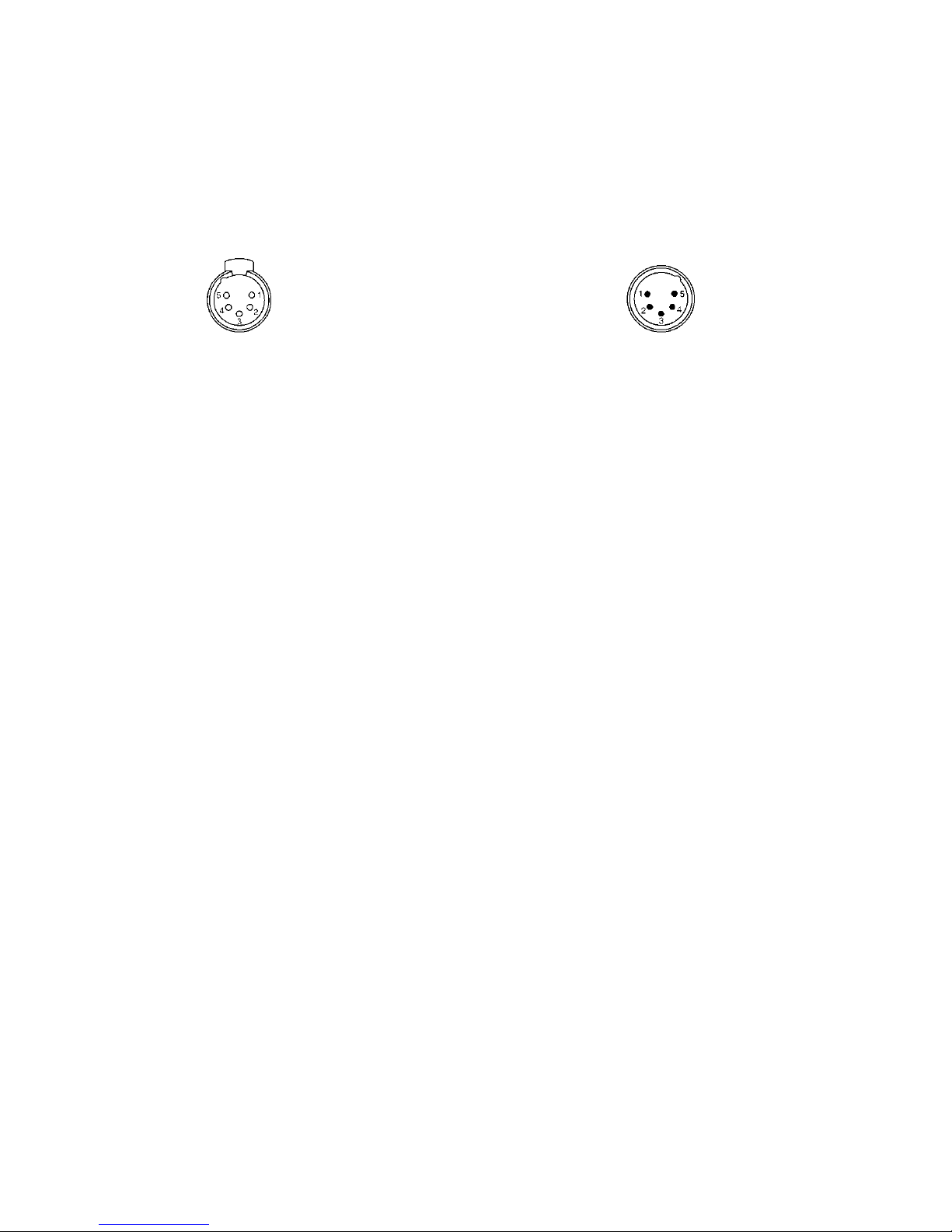
The fi ture is equipped with 5-pin XLR sockets for DMX input and output.
Only use a shielded twisted-pair cable
designed for RS-485 and 5-pin XLR- connectors in order to connect the controller with the fi ture or one fi ture
with another.
Wiring of the XLR connectors:
DMX output DMX input
XLR socket (rear view): XLR plug (rear view):
1– Shield 2 - Signal (-) 3- Signal (+) 4– Not connected 5– Not connected
To build a DMX chain
1. Connect the DMX output of the controller directly with the DMX input of the first fi ture in the DMX chain.
2. Connect the DMX output of the first fi ture in the DMX chain with the DMX input of the ne t fi ture.
3. Always connect the DMX output with the input of the ne t fi ture until all fi tures are connected.
Do not overload the link. Ma . 32 fi tures may be connected on a DMX link.
Terminate the link by installing a termination plug in the output of the last fi ture. The termination plug is a male
5-pin XLR plug with a 120 Ohm resistor connected between Signal (–) and Signal (+).
3.6 Master/slave connection
To build a master/slave-chain:
Connect the DMX output of the master fi ture in the data chain with the DMX input of the first slave. Always
connect output with the input of the ne t slave until all slaves are connected (up to 32 fi tures).
Caution: It is necessary to terminate the input of the master fi ture and the output of the last slave with a 120 Ohm
resistor in order to ensure the proper transmission on the data link.
3.6 Stand alone operation
The fi tures on a data link are not connected to the controller but can e ecute pre-set programs which can be
different for every fi ture. To set the program to be played, see the "Stand-alone setting" (menu "St.AL.").
"Stand-alone operation" can be applied to the single fi ture or to multiple fi tures operating synchronously.
Synchronous operation of multiple fi tures requires that they must be connected on a data link and one of them is
set as a master (master mode) and the rest as the slaves (slave mode).
To set the fi ture as the master or slave, see the " Fi ture Address " (menu "A001").
Only one fi ture can be set as the master.
The master fi ture starts simultaneous program start in the other slave fi tures. All fi tures have a definite,
synchronized starting point when playing back their programs. The number of running program is the same in all
slaves and depends on the master's choice (menu "St.AL.“). Every fi ture runs its program repeatedly, starting the
program step No.1 when requested by the master.
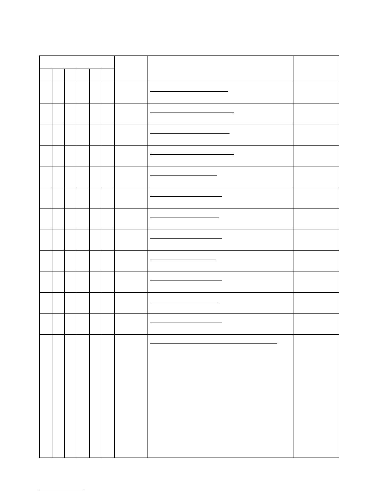
E ample:
If the slave fi ture has a shorter program length, it will continuously repeat its program until the master fi ture
finishes its own program and restarts its program running (slave 1- prog.step 3 will not be finished).
If the slave fi ture has a longer program length, it will restart at prog. step 1 before it completes all its prog.steps
(slave 2 - prog.step 5 will not be played)- see the picture bellow.

CitySkape Xtreme (RGBW)
9
Note: Disconnect the fi tures from the DMX controller before master/slave operating, otherwise data collisions
can occur and the fi tures will not work properly!

CitySkape Xtreme (RGBW)
10
4. CitySkape Xtreme (RGBCW) DMX protocol
Version 1.1
Mode/Channel
Value Function Type of control
1
2
*
3
4
5
6
-
1
1
1
-
-
0 - 255
Red L Ds
-
both
L D
modules
Red LEDs saturation control (0-100%)
proportional
-
2
2
2
-
-
0 - 255
Green L Ds
-
b
oth
L D m
odules
Green LEDs saturation control (0-100%)
proportional
-
3
3
3
-
-
0 - 255
Blue L Ds
-
b
oth
L D
modules
Blue LEDs saturation control (0-100%)
proportional
-
-
4
4
-
-
0 - 255
White L Ds
-
b
oth
L D
modules
White LEDs saturation control (0-100%)
proportional
-
-
-
-
1
1
0 - 255
Red L Ds
–
L D
module
1
Red LEDs saturation control (0-100%)
proportional
-
-
-
-
2
2
0 - 255
Green L Ds
-
L D
module
1
Green LEDs saturation control (0-100%)
proportional
-
-
-
-
3
3
0 - 255
Blue L Ds
-
L D
module
1
Blue LEDs saturation control (0-100%)
proportional
-
-
-
-
4
4
0 - 255
White L Ds
-
L D
module
1
White LEDs saturation control (0-100%)
proportional
-
-
-
-
5
5
0 - 255
Red L Ds
-
L D
module
2
Red LEDs saturation control (0-100%)
proportional
-
-
-
-
6
6
0 - 255
Green L Ds
-
L D
module
2
Green LEDs saturation control (0-100%)
proportional
-
-
-
-
7
7
0 - 255
Blue L Ds
-
L D
module
2
Blue LEDs saturation control (0-100%)
proportional
-
-
-
-
8
8
0 - 255
White L Ds
-
L D
module
2
White LEDs saturation control (0-100%)
proportional
1
-
-
5
-
9
0
1-15
16
17-55
56
57 - 95
96
97 – 134
135
136 - 174
175
176 -214
215
Colour
m
acros
(255 values)
–
both
L D
modules
No function (for DMX mode 4 and 6)
White (for DMX mode 1)
White tones (coolwarm)
Blue (Blue=full, Red+Green+White=0)
Red=0, Greenup,Blue =full, White=0
Light Blue (Red=0, Green=full, Blue =full, White=0)
Red=0, Green=full, Bluedown, White=0
Green (Red=0, Green=full, Blue =0, White=0)
Redup, Green=full, Blue=0, White=0
Yellow (Red=full, Green=full, Blue=0, White=0)
Red=full, Greendown, Blue=0, White=0
Red(Red=full, Green=0, Blue=0, White=0)
Red=full, Green=0, Blueup, White=0
Magenta (Red=full, Green=0, Blue=full, White=0)
step
proportional
step
proportional
step
proportional
step
proportional
step
proportional
step
proportional
step

CitySkape Xtreme (RGBW)
11
Mode/Channel
Value
Function
Type of control
1
2
*
3
4
5
6
1
-
-
5
-
9
216 - 254
255
Colour
m
acros
–
both
L D
modules
Reddown, Green=0, Blue=full, White=0
Blue (Red=0, Green=0, Blue=full, White=0)
proportional
step
-
-
-
6
-
10
0-31
32-63
64-95
96-127
128-143
144-159
160-191
192-223
224-255
Shutter
/
Strobe
–
both
L D
modules
Shutter closed
Shutter open
Strobe-effect from slow to fast
Shutter open
Opening pulses in sequences slow--> fast
Closing pulses in sequences fast --> slow
Shutter open
Random strobe-effects from slow to fast
Shutter open
step
step
proportional
step
proportional
proportional
step
proportional
step
2
-
-
7
-
11
0 - 255
Dimmer
–
both
L D
modules
Dimmer intensity from 0% to 100%
proportional
-
-
-
8
-
12
0 - 255
Dimmer
fine
–
both
L D
modules
Fine dimmer intensity from low to high
proportional
*White LEDs lit proportionally when Red+Green+Blue LEDs are saturated together.

CitySkape Xtreme (RGBW)
12
5. Control menu map
Default settings=Bold print
Menu Level 1
Menu Level 2
Menu Level 3
Menu Level 4
Menu Level 5
Menu Level 6
A001
dM.Ad.
001
-
512
MA.SL.
d.AbL
MASt.
SLA
InFo
Poti.
totL
totL
rSEt
rSEt
DM.In.
rEd1
0
-
255
:
F.dim
0
-
255
tEMP.
Cur.t.
boAr.
LEdS
Hi.tE.
boAr.
LEdS
rSEt
boAr.
LEdS
VErS.
IC1
IC2
PErS
dM.Pr.
Mod.1
Mod.2
Mod.3
Mod.4
Mod.5
Mod.
6
dISP.
d.On
On
, Off
d.Int.
20...
100
turn
On,
Off

CitySkape Xtreme (RGBW)
13
Menu Level 1
Menu Level 2
Menu Level 3
Menu Level 4
Menu Level 5
Menu Level 6
tEM.U.
°
C
,
°
F
bALA
On,
Off
C.bAL.
rEd
0..
200
..255
GrE
n
0..........
255
bLu
E
0..
237
..255
Stor
LOAd
FuLL
EcO
In.Po.
rEd1
0
-
255
:
F.dim
0
-
255
Stor.
dFSE
MAn.M.
PrE.C.
rEd1
rE1.1..rE1.
3
:
dimr
dim0...dim.
7
Man.C.
rEd1
0
-
255
:
F.dim
0
-
255
TESt
St.AL.
Auto
Off
tESt
PrG.1
:
PrG.3
PLAY
tESt
PrG.1
:

CitySkape Xtreme (RGBW)
14
Menu Level 1
Menu Level 2
Menu Level 3
Menu Level 4
Menu Level 5
Menu Level 6
PrG.3
Edit
PrG.1
St.01
rEd1
0
-
255
:
:
:
:
PrG.3
St.
68
S.tim.
0
-
25.5
sec
CoPY
SPEC.
rdML
rdMH
Adj.
DMH
rEd1
:
F.dimr
CaL.U.
rEd1
:
W
h
2
Stor.
vAdI*
r
.InF.
No.LI (0
-
100)
r.UnL.
uPd
.
* Only for Wireless DMX version
6. Fixture menu
The control panel menu allows to set the fi ture according to your needs, obtain information on its operation, test
its various parts and lastly program it, if it has to be used in a Stand-alone mode.
The four control buttons on the front have the following functions:
- SCAP button-leaves menu without saving changes.
- NT R button- enters menu, confirms adjusted values and leaves menu.
- UP and - DOWN buttons - move between menu items on the same level, sets values.
After switching the fi ture on, the fi ture display shows the current DMX address:
After switching the fi ture on, the fi ture display shows stored DMX address:
Use the UP/DOWN buttons to scroll through the various menu items. To select desired item, press the ENTER.

CitySkape Xtreme (RGBW)
15
6.1 Fixture Address
Use this menu to set the DMX address of the fi ture or set the fi ture as a Master (Slave).
dM.Ad. --- DMX addressing. Select this submenu to set a DMX start address.
To set a DMX address.
1. Use the UP/DOWN buttons to find “ A001“ menu.
2. Press the ENTER button.
3. Use the UP/DOWN buttons to select desired start address.
4. Press the ENTER button to confirm the choice.
MA.SL. --- Master/slave addressing (Wire DMX version only). Select this submenu to set the fi ture as a master or
slave. Option "d.AbL" deactivates master/slave setting.
To set a fi ture as a master or slave.
1. Use the UP/DOWN buttons to find “A001“ menu.
2. Press the ENTER button.
3. Use the UP/DOWN buttons to select “ MA.SL.“ item.
4. Press the ENTER button.
5. Use the UP/DOWN buttons to select either master (MASt) or slave (SLA)
6. Press the ENTER button to confirm the choice.
Note: After switching on, the CitySkape Xtreme will automatically detect whether DMX 512 data is received or not.
If there is no data received at the DMX input, the display will start to flash “A001” with actually set address.
6.2 Fixture information
Use this menu to read useful information about the fi ture status.
To display desired information.
1. Use the UP/DOWN buttons to find the “ InFo“ menu.
2. Press the ENTER button.
3. Use the UP/DOWN buttons to select the required menu item.
4. Press the ENTER button to confirm the choice.
Po.ti. --- Power On Time. Use the menu item to read the number of operation hours for each LEDs operating
mode.
totL - the function shows the total number of the operation hours since the CitySkape Xtreme has
been fabricated.
r S t - the function shows the number of the operation hours that the CitySkape Xtreme
has been powered on since the counter was last reset. In order to reset this
counter to 0 you have to press and hold the UP and DOWN buttons and at the same time press
the ENTER button.
DM.In.---DMX values. Select this function to read DMX values of each channel received by the fi ture.
t MP --- Fixture Temperatures. Select this menu to read the temperatures of the fi ture:
Cur.t. --- the current temperature of the fi ture inside.
Hi.t . - the menu item shows the ma . temperatures of the fi ture inside since
the CitySkape Xtreme has been fabricated.
rS t --- the menu item shows the ma imum temperatures of the fi ture inside since the counter
was last reset. In order to reset this counter to 0 you have to press and hold the UP and DOWN
buttons and at the same time press the ENTER button.

CitySkape Xtreme (RGBW)
16
Note: The ambient temperature should not e ceed 40°C.
Measuring points:
L dS.--- the temperature of the LEDs module.
boAr. --- the temperature on the PCB in the fi ture head.
The temperatures can be displayed in either °C or °F units - see option “tEM.U“ in the menu “Pers“.
V rS. ---Software Versions. Select this function to read the software versions of the fi ture processors.
IC1 --- the processor controls LED modules
IC2 --- EEprom
6.3 Personality
Use this menu to modify the CitySkape Xtreme operating behaviour.
DM.Pr. --- DMX preset. Select this menu item to set a desired DMX mode. Please refer to the chapter "DMX
protocol" for detail description of each DMX mode.
DiSP. --- Display adjusting. This function allows you to change the display settings.
d.On --- this function allows you to keep the display on or to turn off automatically 2 minutes
after last pressing any button on the control panel.
d.Int. --- select this function to adjust the display intensity (20-min.,100-ma .).
turn --- select this function to turn the display by 180°.
t M.U. --- Temperature Unit. Use this menu in order to display the fi ture temperatures in desired units: °C or °F.
bALA --- Balance Use this menu item to enable (On) or disable (Off) the white balance which is set in the “White
colour balance“ menu below. I f this function is set off, the CitySkape Xtreme will use ma imum values (255) of
saturation for red, green and blue colour. This function has to be set on before adjusting a white balance.
C.bAL. --- White Colour Balance. The menu gives access to the setting of the white balance.
To set the white colour balance.
1. Use a DMX controller or the “ Man.C.“ menu to set all LEDs on ma . saturation.
2. Use the UP/DOWN buttons to find the “ Pers.“ menu.
3. Press the ENTER button.
4. Use the UP/DOWN buttons to select the “C.bAL“menu.
5. Press the ENTER button and the “rEd“ item will appear on the display.
6. Press the ENTER button and use the UP/DOWN buttons to set new ma . value for the red LEDs.
7. Press the ENTER button to confirm the choice.
8. Use the UP/DOWN buttons to select ne t colour, the “GrEn“.
9. Repeat steps 6-7 for this channel.
10. Use the UP/DOWN buttons to select the last colour, the „bLuE“ and repeat steps 6-7 for this colour.
LoAd --- Load of L Ds. The menu allows to choose 2 different operating modes for fi ture´s LEDs.
FuLL --- Ma imum light output.
cO. --- The light output is decreased by 25%.
In.Po. --- Init effect positions. Use this function to set all effects to the desired positions to which they will move
after switching the fi ture on (if DMX is not being received).
Note. If DMX mode 1 is selected, only values set at items “MACr” (macro) and dinr (dimmer) will be accepted.
dF.S . --- Default Settings .The menu item sets all fi ture parameters to the default (factory) values.

CitySkape Xtreme (RGBW)
17
6.4 Manual mode
Use this menu for control the fi ture without connected DMX console.
Pr .C. --- Preset effects control. Select this menu to call up preset positions of the channel effects.
Man.C. --- Manual effect control. Select this menu to control all channels via buttons of the control board.
To control fi ture channels.
1. Use the UP/DOWN buttons to find “ Man.C“ menu.
2. Press the ENTER button.
3. Use the UP/DOWN buttons to select desired effect (channel).
List of control channels:
“rEd1” - “rEd2” - red LEDs saturations, LED modules 1 and 2
“GrE1“ - “GrE2“ - green LEDs saturations, LED modules 1 and 2
“bLu1“ - “bLu2“ - blue LEDs saturations, LED modules 1 and 2
“Whi1“ - “Whi2“ white LEDs saturations, LED modules 1 and 2
“MACr“ - colour macros
“Stro.“ - a strobe, shutter
“dimr“ - a dimmer
4. Press the ENTER button and use the UP/DOWN buttons to set value , press the ENTER button to confirm it.
6. 5 Test sequences
Use this menu to run demo-test sequences without an e ternal controller, which will show you some possibilities
of using the CitySkape E treme.
6.6 Stand alone setting
The fi tures on a data link are not connected to the controller but can e ecute pre-set programs which can be
different for every fi ture. “Stand-alone operation” can be applied to the single fi ture or to multiple fi tures
operating synchronously.
Synchronous operation of multiple fi tures requires that they must be connected on a data link and one of them is
set as a master (“MASt“) and the rest as the slaves (“SLA“). Up to 32 fi tures can be connected in a master/slave
chain. Only one fi ture can be set as the master.
Note: Disconnect the fi tures from the DMX controller before master/slave operating, otherwise data collisions can
occur and the fi tures will not work properly. See the chapters “Stand-alone operation“ and “ Master/slave
connection“.
Auto. --- Automatic playback. This function allows you to select the program which will be played after switching
the fi ture on. Selected program will be played continuously in a loop.
1. Use the UP/DOWN buttons to find “ St.AL.“ menu.
2. Press the ENTER button.
3. Use the UP/DOWN buttons to select “ Auto“ item.
4. Press the ENTER button.
5. Use the UP/DOWN buttons to select desired program.
6. Press the ENTER button to confirm the choice.
PLAY --- Playing program. By enter to this menu a complete overview of all programs is offered, from which the
program to be run can be selected.

CitySkape Xtreme (RGBW)
18
1. Use the UP/DOWN buttons to find “ St.AL.“ menu.
2. Press the ENTER button.
3. Use the UP/DOWN buttons to select desired program.
4. Press the ENTER button. The selected program runs in a loop.
dit --- diting a program. The fi ture offers 3 freely editable programs (EPG.1-EPG.3) each up to 68 steps. Every
program step includes a fade time-the time taken by the step´s channel status to reach the desired level and a
step time-the total time occupied by the step in the program.
E.g. If “F.tim.“=5 second and “S.tim.“=20 second, effects will go to the desired position during 5 seconds and after
that they will stay in this position for 15 seconds before going to the ne t prog. step
1. 1. Use the UP/DOWN buttons to find “ St.AL.“ menu and press the ENTER button.
2. Use the UP/DOWN buttons to select “Edit“ menu and press the ENTER button.
3. Use the UP/DOWN buttons to select a program you want to edit (PrG.1-PrG.3 and press ENTER button.
4. Use the UP/DOWN buttons to select a desired program step ("St.01" - "St.68") and press ENTER button.
5. Use the UP/DOWN buttons to select a channel you want to edit and press the ENTER button.
List of editable items:
“P.End” - a total number of the program steps (value 1-68). This value should be set before start
Programming (e.g. if you want to create program with 10 steps, set P.End=10).
“rEd1” - “rEd2” – a red LEDs saturation(0-255), module 1-2
“GrE1“ - “GrE2“ –a green LEDs saturation (0-255) ), module 1-2
“bLu1“ - “bLu2“ – a blue LEDs saturation (0-255) ), module 1-2
“Whi1“ - “Whi2“ – a white LEDs saturation (0-255) ), module 1-2
“MACr“ - colour macros (0-255), both modules
“Stro.“ - a strobe, shutter (0-255), both modules
“dimr“ - a dimmer (0-255), both modules
“F.tim.“ - a fade time, (0-25.5) seconds
“S.tim.“ - step time, value (0-25.5) seconds
“COPY“. – this item duplicates the current prog. step to the ne t prog. step. The item “P.End” is increased
automatically.
6. Use the UP/DOWN buttons to set a DMX value of the channel and then press the ENTER button.
7. Use the UP/DOWN buttons to select ne t channel and press the ENTER button.
8. After having set all channels in the current program step, press the MODE button to go by one menu level
back and select another program step.
6.7 Special functions
rdML --- Code.This menu item shows the first part of the RDM identification code.
rdMH --- Code. This menu item shows the second part of the RDM identification code.
AdJ --- ffect Adjustment. The menu allows calibration of each LEDs array.
dMH --- DMX Values. The menu item enables to control all LEDs before calibrating each LEDs array.
CAL.U --- Calibrating unit. The menu serves for fine current calibration of LEDs during fi ture burn-in at
a factory. Each LED array can be calibrated separately. Users should not change the setting.
rAdI --- Wireless DMX. The menu serves for reading of the wireless operation status (only for wireless DMX
version).
r.InF. --- Wireless DMX information. The menu item shows level of received signal in %. If the fi ture is not
linked to the transmitter, “no.LI” is displayed.
r.UnL. --- Wireless DMX unlink. The item serves for unlinking the fi ture from transmitter.

CitySkape Xtreme (RGBW)
19
uPd.M. --- Updating mode. The menu item allows you to update software in the fi ture via either serial or USB port
of PC.
The following are required in order to update software:
- PC running Windows 95/98/2000/XP or Linu
- DMX Software Uploader
- Flash cable RS232/DMX No.13050624 (if you want to use a serial port of PC)
- Robe Universal Interface (if you want to use an USB port of PC)
Note1: Software update should e ecute a qualified person. If you lack qualification, do not attempt the update
yourself and ask for help your ROBE distributor.
Note 2: DMX address, programs 1-3 and all items in the menu "PErS" will be set to their default values.
To update software in the fixture:
I. Installation of the DMX Software Uploader.
1. DMX Software Uploader program is available from the ROBE web site at WWW.robe.cz.
2. Make a new directory ( e.g. Robe_Uploader) on your hard disk and download the software to it.
3. Unpack the program from the archive.
.
II.Fi ture software updating.
1. Determine which of your port is available on your PC and connect it:
-with the DMX input of the fi ture if you using the flash cable RS232/DMX
-with the DMX input of the Robe Universal Interface if you using the USB cable.
Disconnect the fi ture from the other fi tures in a DMX chain. Turn both the computer and the fi ture on.
Make sure the lamp is switched off (only if the fi ture involves a lamp).
2. Switch the fi ture to the updating mode:
1Use the UP/DOWN buttons to find “SP C.“ menu.
2Press the ENTER button.
3Use the UP/DOWN buttons to select “ uPd.“ item.
4Press the ENTER button
5Use the UP/DOWN buttons to select “ y S“ option
6Press the ENTER button
Note: If you do not want to continue in software update, you have to switch off and on the fi ture
to escape from this menu.
3. We recommend to cancel all running programs before start of the Software Uploader.
4. Run the Software Uploader program. Select desired COM and then click on the Connect button.
Select DreamBo 1
if the USB port is
used.
Select COM if the
serial port is used.

CitySkape Xtreme (RGBW)
20
If the connection is OK, click on the Start Uploading button to start uploading. It will take several minutes
to perform software update. If the option "Incremental Update" is not checked, all processors will be
updated (including processors with the same software version).
If you wish to update only later versions of processors, check the Incremental Update bo .
Avoid interrupting the process. Update status is being displayed in the Info Bo window.
When the update is finished, the line with the te t “The fi ture is successfully updated‘will appear in
this window and the fi ture will reset with the new software.
Note: In the case of an interruption of the upload process (e.g. power cut), the fi ture keeps the updating mode
and you have to repeat the software update again.
For e ample: The fi ture was switched off before finishing software upload. After switching again the fi ture on,
the fi ture is still in the updating mode and the display is dark. Restart the Software Uploader program and repeat
software update from your PC.
7. RDM
This fi ture is ready for RDM operation.RDM (Remote Device Management) is a bi-directional communications
protocol for use in DMX512 control systems, it is the new open standard for DMX512 device configuration and
status monitoring.
The RDM protocol allows data packets to be inserted into a DMX512 data stream without adversely affecting
e isting non-RDM equipment. By using a special „Start Code,“ and by complying with the timing specifications for
DMX512, the RDM protocol allows a console or dedicated RDM controller to send commands to and receive
messages from specific moving lights.
RDM allows e plicit commands to be sent to a device and responses to be received from it.
The list of commands for CitySkape Xtreme is the following.
Parameter ID Discovery command S T command G T command
DISC_UNIQUE_BRANCH *
DISC_MUTE *
DISC_UN_MUTE *
DEVICE_INFO
*
SUPPORTED_PARAMETERS
*
SOFTWARE_VERSION_LABEL
*
DMX_START_ADDRESS
* *
IDENTIFY_DEVICE
* *
DEVICE_MODEL_DESCRIPTION
*
MANUFACTURER_LABEL
*
DEVICE_LABEL
*
*
SENSOR_DEFINITION
*
SENSOR_VALUE
*
DISPLAY_LEVEL
*
*
DEVICE_RESET
*
This manual suits for next models
1
Table of contents
Other Robe Spotlight manuals
Popular Spotlight manuals by other brands

Honeywell
Honeywell LED150 instruction manual

Miboxer
Miboxer FUT103Z quick start guide

Ego Power+
Ego Power+ LT1000E Operator's manual

DeWalt
DeWalt XR LI-ION DCL043 Original instructions

Heitronic
Heitronic 26072 Installation and operating instructions

Larson Electronics
Larson Electronics HL-85-CPR-MS instruction manual

Home Zone Security
Home Zone Security LK48498V installation instructions

Black & Decker
Black & Decker Power Series 90515795 instruction manual

Black & Decker
Black & Decker FL3WBD instruction manual

Light Sky
Light Sky FLY DRAGON IP2021Profile user manual

PLG
PLG NEXUS 18 240V user manual

ELAN Lighting
ELAN Lighting CAB-330-BEAM-IP user manual