Robern VESPER GLB30MLSS3D User manual
1
© 2020 Robern, Inc. 701 N. Wilson Ave. Bristol, PA 19007 U.S.A.
800.877.2376 www.robern.com
Installation or Assembly Instructions
Part no. 209-1329 rev. 03/25/20
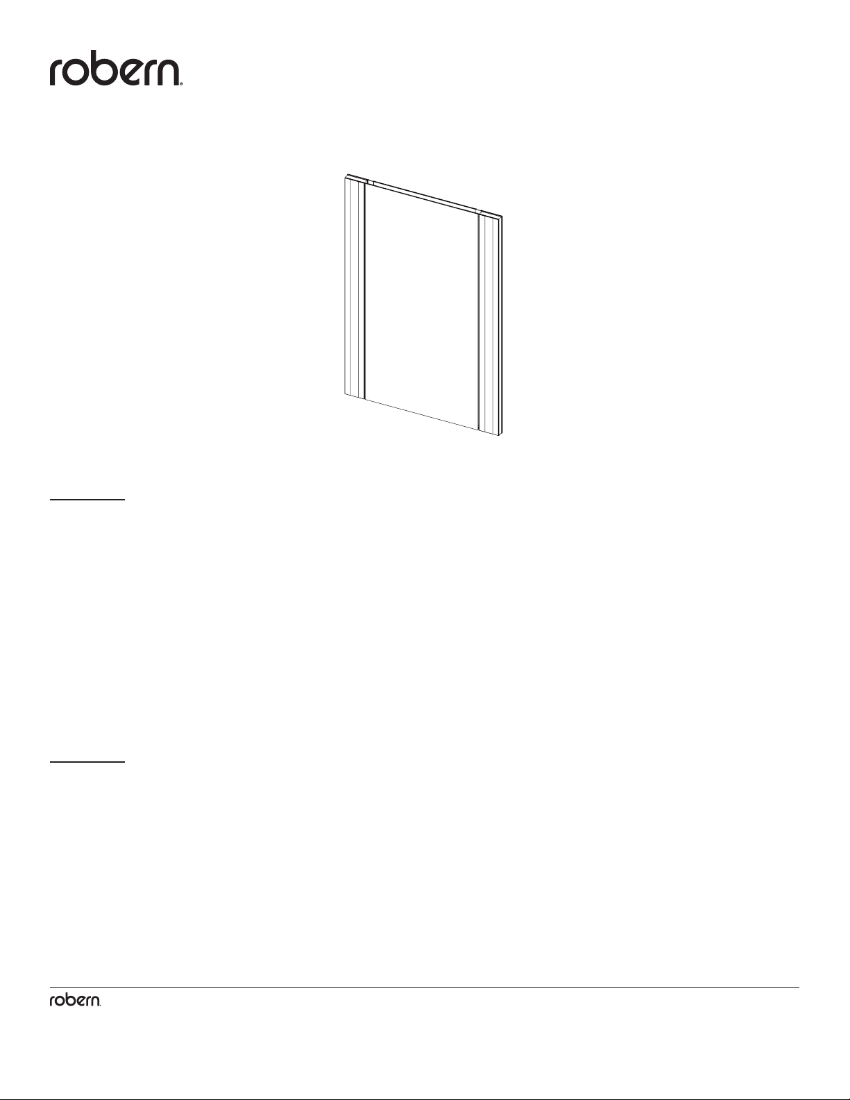
Vesper Midline / Outline Light
VESPER™MIDLINE / OUTLINE LIGHT
Installation Instructions
Important safety instructions - Save these instructions
CONTENTS
Assembling the brackets - 5
Mounting the brackets to the cabinet - 6
Access the Electrical Enclosure - 7
Recess Installation - 8
Surface Mount Installation - 9
Final Assembly - 12
Français / Español - 15
GENERAL INFORMATION
This instruction sheet contains information on how to install the Vesper Midline or Vesper Outline light. This series comes in many
variations. Please refer to the box or product label for the specic model number. A key is provided on page 2.
Save these instructions for future use and reference. An improper installation voids the warranty. Carefully inspect the light for damage.
Installed products cannot be returned.
If you experience any problems with your light, contact your dealer or Robern directly.
Limited Warranty — One Year Term
Suitable for damp locations
2
© 2020 Robern, Inc. 701 N. Wilson Ave. Bristol, PA 19007 U.S.A.
800.877.2376 www.robern.com
Installation or Assembly Instructions
Part no. 209-1329 rev. 03/25/20
Vesper Midline / Outline Light
For dimmable models Robern recommends the Maestro® C•L® Dimmer from LUTRON®, Model # MACL-153M.
http://www.lutron.com/TechnicalDocumentLibrary/369613a.pdf
Other LED control dimmers may operate with this product but have not been tested or veried. It's recommended that the dimmer be
within reach of your mirror so you can adjust the brightness.
For on/off (non-dimming) operation a standard wall switch may be substituted in place of the dimmer.
DIMMER RECOMMENDATIONS
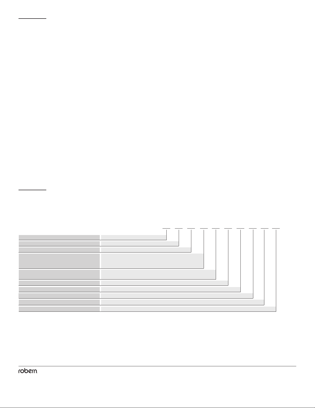
Model Numbers G L B 40 M L S S 3D
Product Line G = Vesper
L = Lights
M = Midline
U = Outline
L = LED
3 = 3000K
S = Single Lamp
D = Dimmable
S = Silver
Light Name
Width
Quantity of Lamps
Engine Type
Category
Type of Lamp
Color Temperature
Height
Main Body Color
MODEL NUMBERS
Use the chart below to learn how to read your light model number. This chart references the model number for a 2.75" W x 40" H
Vesper Midline Light with a silver metal nish. Consult the Robern Price Book for a complete list of model numbers.
B = 2-3/4" / 70 mm
30 = 30" / 762 mm
36 = 36" / 914 mm
40 = 39-3/8" / 1000 mm
3
© 2020 Robern, Inc. 701 N. Wilson Ave. Bristol, PA 19007 U.S.A.
800.877.2376 www.robern.com
Installation or Assembly Instructions
Part no. 209-1329 rev. 03/25/20
Vesper Midline / Outline Light
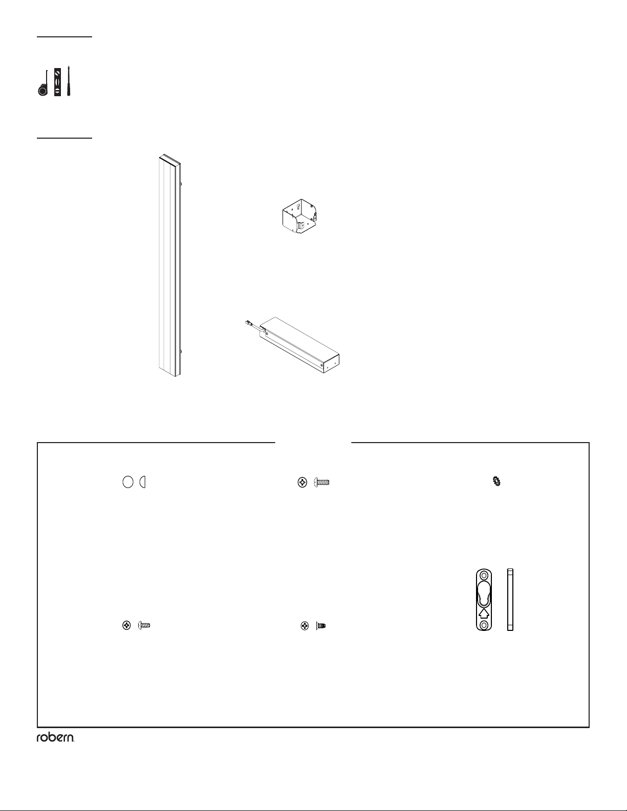
TOOLS NEEDED
PARTS
Hardware Bag*
[216-1197]
[210-1709]
(2) Mounting Brackets
(1) Midline/Outline Light
[205-3176]
(1) Electrical Enclosure
* Depending on installation, not all parts will be used
[SS672]
(6) #10 Screw Cap
210-1661
(4) Mounting Brackets
(1) Midline/Outline
Lights
216-1197
(1) Hardware Bag
216-1195
(1) Hardware Bag
(2) Edgeline
Lights
SS672
(12) #10 Screw Cap
203-1068
(3) #8 Lock Washer
SS344
(2) Screw, #8 x 3/8"
203-1497
(9) Screw, #8 x 3/8" Flat
SS676
(8) Screw, #10 x 1/2"
SS675
(4) Screw, #10 x 3"
211-1362
(4) Button Receiver
211-1351
(1) Mounting Button
219-1076
(1) Cable Tie Holder
203-1089
(1) Cable Tie, 4"
(1) Electrical Enclosure
205-3176
(1) Electrical Enclosure
210-1709
(2) Mounting Brackets
SS672
(6) #10 Screw Cap
SS676
(4) Screw, #10 x 1/2"
SS344
(2) Screw, #8 x 3/8"
203-1068
(3) #8 Lock Washer
203-1497
(5) Screw, #8 x 3/8" Flat
211-1362
(2) Button Receiver
211-1351
(1) Mounting Button
[SS676]
(4) Screw, #10 x 1/2"
[203-1497]
(4) Screw, #8 x 3/8" Flat
[SS344]
(2) Screw, #8 x 3/8"
[203-1068]
(2) #8 Lock Washer
[211-1362]
(2) Button Receiver
210-1661
(4) Mounting Brackets
(1) Midline/Outline
Lights
216-1197
(1) Hardware Bag
216-1195
(1) Hardware Bag
(2) Edgeline
Lights
SS672
(12) #10 Screw Cap
203-1068
(3) #8 Lock Washer
SS344
(2) Screw, #8 x 3/8"
203-1497
(9) Screw, #8 x 3/8" Flat
SS676
(8) Screw, #10 x 1/2"
SS675
(4) Screw, #10 x 3"
211-1362
(4) Button Receiver
211-1351
(1) Mounting Button
219-1076
(1) Cable Tie Holder
203-1089
(1) Cable Tie, 4"
(1) Electrical Enclosure
205-3176
(1) Electrical Enclosure
210-1709
(2) Mounting Brackets
SS672
(6) #10 Screw Cap
SS676
(4) Screw, #10 x 1/2"
SS344
(2) Screw, #8 x 3/8"
203-1068
(3) #8 Lock Washer
203-1497
(5) Screw, #8 x 3/8" Flat
211-1362
(2) Button Receiver
211-1351
(1) Mounting Button
4
© 2020 Robern, Inc. 701 N. Wilson Ave. Bristol, PA 19007 U.S.A.
800.877.2376 www.robern.com
Installation or Assembly Instructions
Part no. 209-1329 rev. 03/25/20
Vesper Midline / Outline Light
Unpack the Light. Check the box thoroughly for all hardware and loose parts. Carefully inspect the xture for damage.
DANGER: Risk of personal injury. To avoid possible electrical shock, the electricity must be turned off at the circuit
breaker or fuse box before attempting any installation procedure.
DANGER: Risk of personal injury. To avoid possible electrical shock, the light xture must be properly grounded.
CAUTION: Grounding instructions for permanently connected products: This product must be connected to a grounded,
metal permanent wiring system or an equipment-grounding conductor must be run with the circuit conductors and connected to the
equipment-grounding terminal or lead on the product. All wiring should be done by a qualied licensed electrician.
IMPORTANT: Power for the lights should be provided separately from the electricity to the cabinet so that when lights are turned off,
cabinet electricity remains on.
NOTE: Requires minimum 120 VAC 15 amp circuit.
NOTE: Requires an approved compatible dimmer for installation (not included). Refer to the dimmer recommendation on page 2.
Observe all applicable electrical codes and building codes. Wire the light xtures in accordance with the electrical codes.
This xture is for indoor use only.
This installation may require the assistance of more than one person depending on your Light/Cabinet conguration.
NOTES
DANGER - RISK OF SHOCK -
DISCONNECT POWER BEFORE INSTALLATION
5
© 2020 Robern, Inc. 701 N. Wilson Ave. Bristol, PA 19007 U.S.A.
800.877.2376 www.robern.com
Installation or Assembly Instructions
Part no. 209-1329 rev. 03/25/20
Vesper Midline / Outline Light
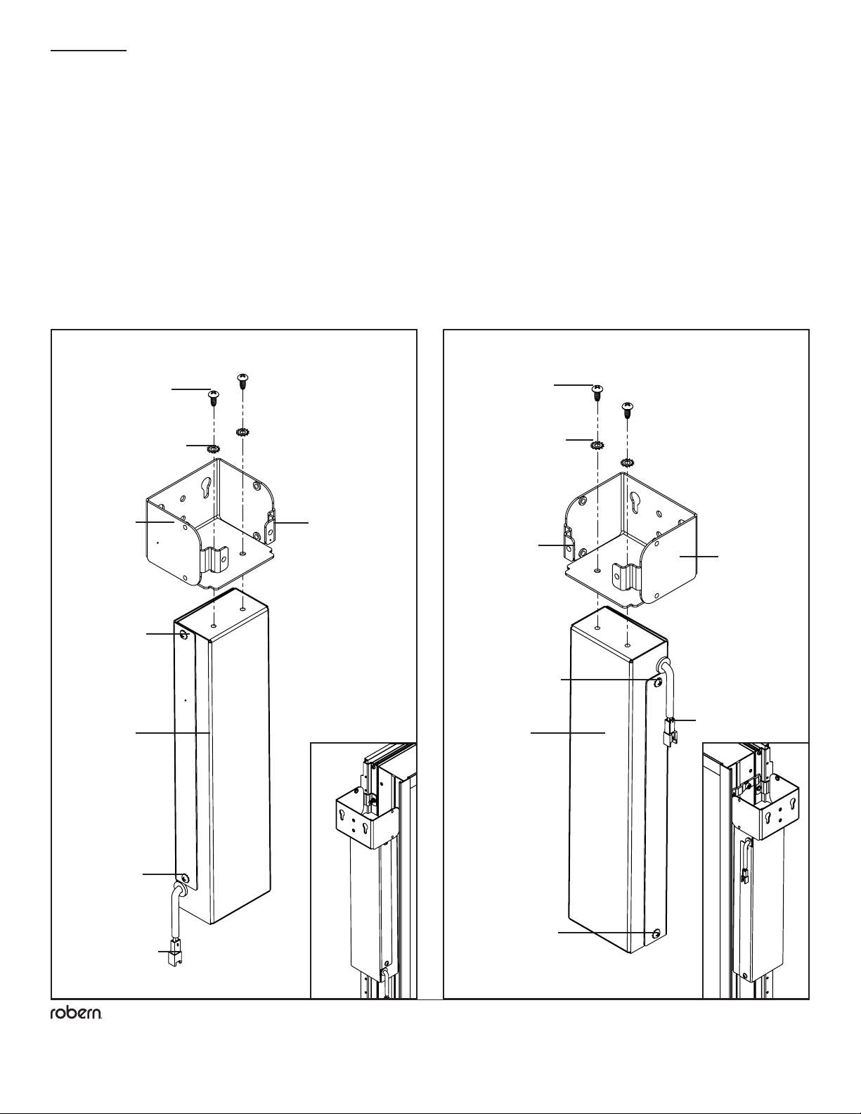
STEP 1 - ASSEMBLING THE BRACKETS
Note: A RH (Right Hand) installation will require the electrical enclosure to be ipped, placing the exiting low voltage wire
closer to the upper bracket.
1. Orient one of the mounting brackets [210-1709] (as shown) ensuring that the electrical access screws on the electrical enclosure
[205-3176] are pointed toward the front of the cabinet.
2. Attach the included electrical enclosure [205-3176] to the bracket using the supplied #8 screws [SS344] and lockwashers [203-1068].
SS344 SS344
203-1068 203-1068
210-1709
205-3176 205-3176
Electrical
access screws
Low voltage wire
connection
Tabs always face
cabinet box
LH Installation RH Installation
Tabs always face
cabinet box
210-1709
Electrical
access screws
Electrical
access screws
Electrical
access screws
Low voltage wire
connection

6
© 2020 Robern, Inc. 701 N. Wilson Ave. Bristol, PA 19007 U.S.A.
800.877.2376 www.robern.com
Installation or Assembly Instructions
Part no. 209-1329 rev. 03/25/20
Vesper Midline / Outline Light
STEP 2 - MOUNTING THE BRACKETS TO THE CABINET
Note: Do not completely tighten the screws. This will allow for any adjustments in later steps.
1. Mount the brackets to the cabinet through the ganging locations, as shown, using the supplied #10 screws [SS676].
SS676
SS676

7
© 2020 Robern, Inc. 701 N. Wilson Ave. Bristol, PA 19007 U.S.A.
800.877.2376 www.robern.com
Installation or Assembly Instructions
Part no. 209-1329 rev. 03/25/20
Vesper Midline / Outline Light
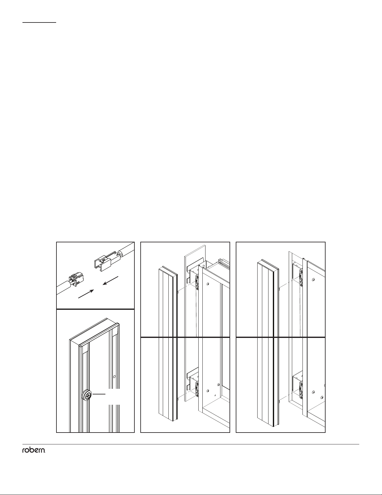
STEP 3 - ACCESS THE ELECTRICAL ENCLOSURE
Lay the cabinet on a at level surface.
1. Remove the two electrical access screws [203-1159] and lockwashers [203-1525] to access the electrical wiring connections
2. Set all hardware and electrical cover(s) aside in a safe place.
203-1159
203-1525
1
* Make proper connections
according to the dimmer
manufacturer's instructions
CIRCUIT BREAKER
120VAC
15A
DIMMER*
FIELD CONNECTION
ELECTRICAL ENCLOSURE
LINE/BLACK
NEUTRAL/WHITE
GROUND
BLACK
WHITE
GROUND
8
© 2020 Robern, Inc. 701 N. Wilson Ave. Bristol, PA 19007 U.S.A.
800.877.2376 www.robern.com
Installation or Assembly Instructions
Part no. 209-1329 rev. 03/25/20
Vesper Midline / Outline Light
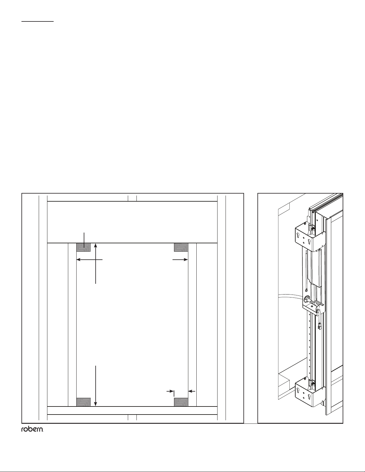
STEP 4A - RECESS INSTALLATION
1. With the electrical cover(s) removed, support the cabinet on the edge of the recessed opening and feed the eld wire(s) through the
eld wire strain relief at the back of each enclosure(s).
2. Push the cabinet assembly into the recessed opening until the back of the cabinet ange is tight to the nished wall surface.
3.Using a level, level and plumb the products in the opening. Shim as necessary. Using a square, make sure the cabinet is
square in all axis.
4. Make the electrical connection(s) according to the electrical diagram on page 7.
Note: Refer to your cabinet's Instructions to insure there are no additional steps required prior to proceeding.
5. Mount the cabinet in place using the #10 Screws [SS674] provided with the cabinet.
RO Width =
Width of cabinet +
width of lights - 3/4" (19 mm)
RO Height =
Height of cabinet - 3/4" (19 mm)
Corner block 2x4
4x corners
2-1/2" (63.5 mm)

9
© 2020 Robern, Inc. 701 N. Wilson Ave. Bristol, PA 19007 U.S.A.
800.877.2376 www.robern.com
Installation or Assembly Instructions
Part no. 209-1329 rev. 03/25/20
Vesper Midline / Outline Light
C
LC
L
STEP 4B - SURFACE MOUNT INSTALLATION
1. With the electrical cover(s) removed, feed the eld wire(s) through the eld wire strain relief(s) at the back of the electrical
enclosure(s).
Note: Refer to your cabinet's Instructions to insure there are no additional assembly steps required prior to proceeding.
2. Mount the cabinet in place following the steps provided in the cabinet's instructions.
3. Make the electrical connection(s) according to the electrical diagram on page 7.
1
Cabinet Width + 3/4"
30 = 16-1/2" (419 mm)
36 = 22-1/2" (572 mm)
40 = 25-7/8 (657 mm)
Left Hand (LH) electrical
enclosure installation
eld wire stub out
30 = 24-3/4" (629 mm)
36 = 30-3/4" (781 mm)
40 = 34-1/8 (867 mm)
Right Hand (RH) electrical
enclosure installation
eld wire stub out
10
© 2020 Robern, Inc. 701 N. Wilson Ave. Bristol, PA 19007 U.S.A.
800.877.2376 www.robern.com
Installation or Assembly Instructions
Part no. 209-1329 rev. 03/25/20
Vesper Midline / Outline Light
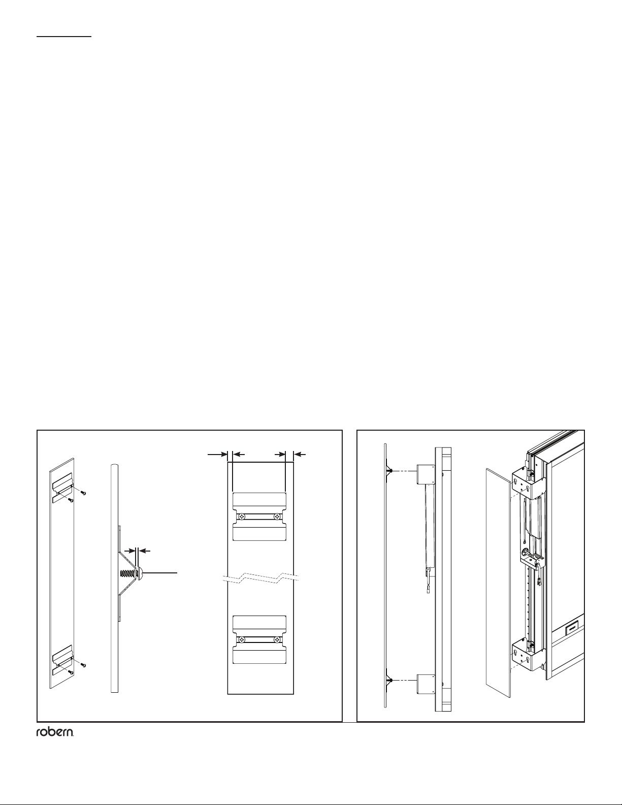
STEP 4B - SURFACE MOUNT INSTALLATION, SIDE KITS
4. Drive the #10 Screws [SS676] provided with the Surface Mount Kit (sold separately) into the holes in the side kit brackets. Use a
penny (as detailed in gure 4 below) to set the depth distance.
5. Orienting the sidekit as shown below, insert the Screw Heads into the keyholes on the side of the upper and lower Light Brackets.
Note: If the bracket is not oriented correctly, the side kit cannot be lowered into place and may fall resulting in damage.
6. Slide the Sidekit down into place.
Note: If the Sidekit feels loose, move the sidekit back and forth to determine which screw feels loose. Lift and remove the sidekit from
the brackets and rotate the loose screw a 1/4 turn clockwise, repeating as necessary.
Note: If the Sidekit does not lower into place, remove the sidekit from the keyholes and rotate the screws a 1/4 turn counterclockwise.
SS676
1/16" (1.52 mm)
or the thickness
of a penny.
Front
toward
user
Rear
toward
wall
4 5
11
© 2020 Robern, Inc. 701 N. Wilson Ave. Bristol, PA 19007 U.S.A.
800.877.2376 www.robern.com
Installation or Assembly Instructions
Part no. 209-1329 rev. 03/25/20
Vesper Midline / Outline Light
1
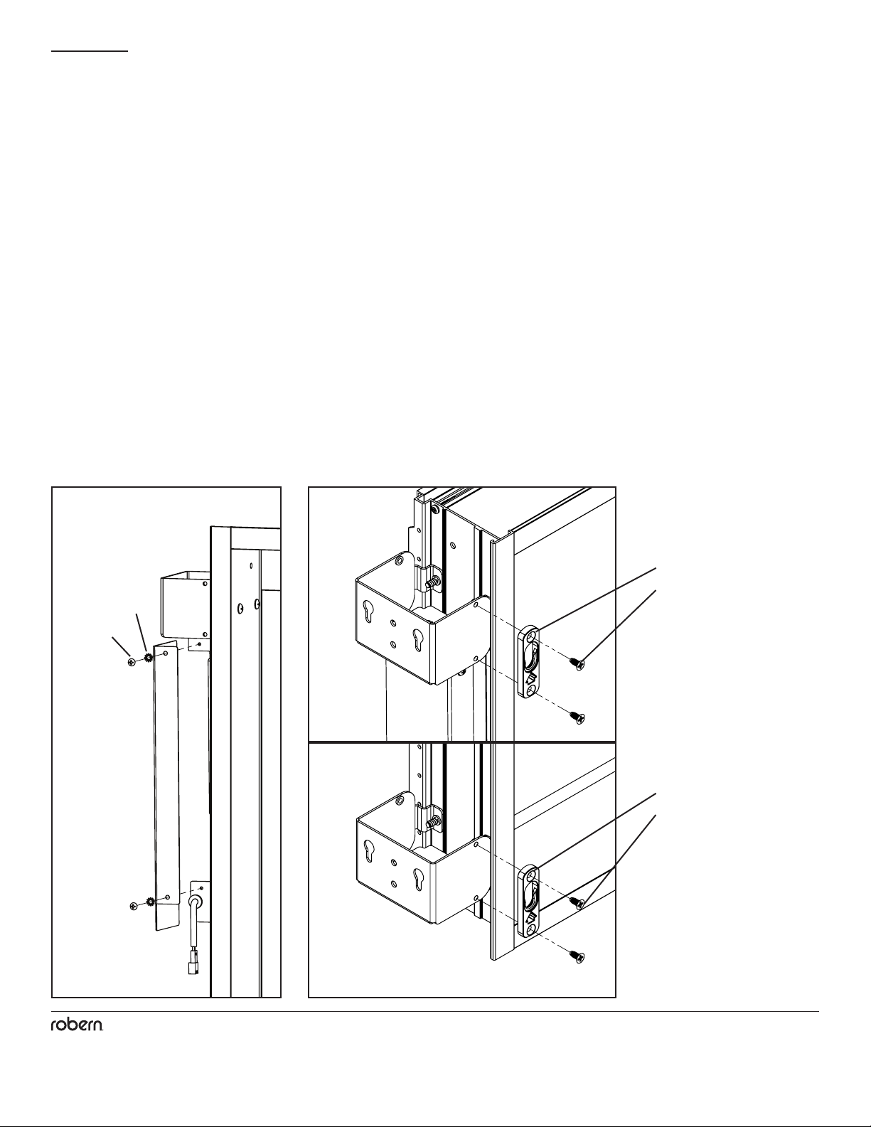
STEP 5 - FINAL ASSEMBLY
1. Using the Electrical access screws [203-1159], lockwashers [203-1525], and Electrical Enclosure Cover set aside in step 3, close the
Electrical Enclosure.
Note: Leaving too much Field Wire in the enclosure could prevent it from closing properly and may cause damage to the internal
components.
2. Using the provided #8 screws [203-1497] attach a button receiver [211-1362] to each bracket. The arrow on the button receiver must
be pointed up.
203-1159
Electrical
access
screws
203-1525
2
211-1362
211-1362
203-1497
203-1497
12
© 2020 Robern, Inc. 701 N. Wilson Ave. Bristol, PA 19007 U.S.A.
800.877.2376 www.robern.com
Installation or Assembly Instructions
Part no. 209-1329 rev. 03/25/20
Vesper Midline / Outline Light
STEP 5 - FINAL ASSEMBLY
3. Connect the electrical connector from the light to the electrical low voltage wire connector coming out of the electrical enclosure.
4. Align and insert the buttons on the back of the light into the upper and lower button receivers [211-1362].
5. Slide the light down until it's completely engaged. Lights will appear to be loose because the brackets are not tight (left loose in
Step 2 Mounting the Brackets to the Cabinet).
4
3Surface Mount Recess Mount
Button
[211-1351]
13
© 2020 Robern, Inc. 701 N. Wilson Ave. Bristol, PA 19007 U.S.A.
800.877.2376 www.robern.com
Installation or Assembly Instructions
Part no. 209-1329 rev. 03/25/20
Vesper Midline / Outline Light
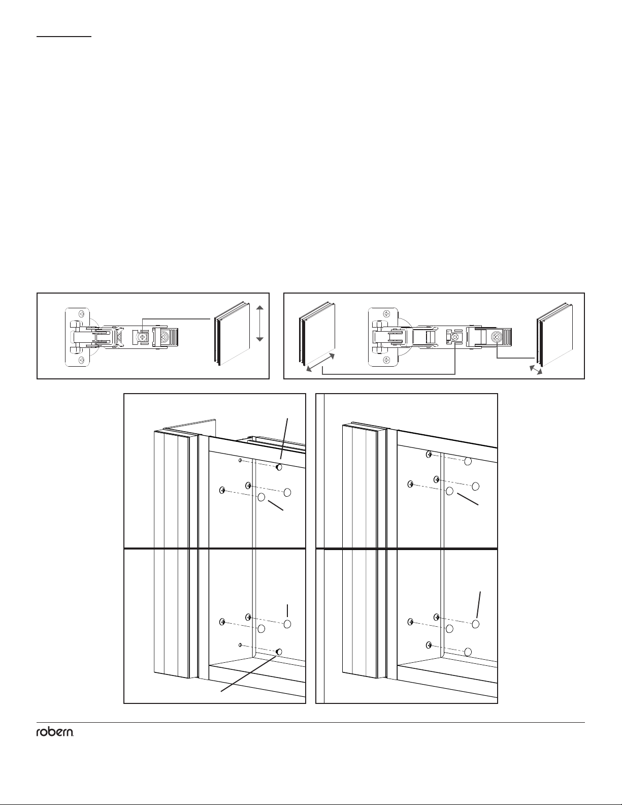
STEP 5 - FINAL ASSEMBLY
6. Adjust the light vertically until it's ush with the top and bottom of the cabinet box.
7. Tighten the mounting screws [SS676] inside the cabinets to complete the light installation.
8. Adjust the cabinet doors until they align with the lights using the three-way adjustment features in the hinges, adjusted using a #2
Phillips Head screwdriver.
8A. Height: With the hinge slightly closed, you can access the middle screw. This screw will move your door front up and down.
8B. Side to Side/Depth: With the hinge fully extended, you can access the front and back screws. The front screw will adjust the door
from side to side and the rear screw will adjust the door's depth.
9. Press a Screw Cap [SS672], provided with each light, onto all exposed screw heads.
10. Press a Hole Plug [SS134], included with your cabinet hardware, into all open mounting holes.
FINAL ASSEMBLY - CAPS AND PLUGS
PRESS A #10 SCREW CAP [SS672], PROVIDED WITH EACH LIGHT, ONTO ALL EXPOSED SCREW HEADS.
1.
PRESS A HOLE PLUG [SS134], INCLUDED WITH YOUR CABINET HARDWARE, INTO ALL OPEN MOUNTING HOLES.
2.
FINAL ASSEMBLY - CAPS AND PLUGS
PRESS A #10 SCREW CAP [SS672], PROVIDED WITH EACH LIGHT, ONTO ALL EXPOSED SCREW HEADS.
1.
PRESS A HOLE PLUG [SS134], INCLUDED WITH YOUR CABINET HARDWARE, INTO ALL OPEN MOUNTING HOLES.
2.
FINAL ASSEMBLY - CAPS AND PLUGS
PRESS A #10 SCREW CAP [SS672], PROVIDED WITH EACH LIGHT, ONTO ALL EXPOSED SCREW HEADS.
1.
PRESS A HOLE PLUG [SS134], INCLUDED WITH YOUR CABINET HARDWARE, INTO ALL OPEN MOUNTING HOLES.
2.
FINAL ASSEMBLY - CAPS AND PLUGS
PRESS A #10 SCREW CAP [SS672], PROVIDED WITH EACH LIGHT, ONTO ALL EXPOSED SCREW HEADS.
1.
PRESS A HOLE PLUG [SS134], INCLUDED WITH YOUR CABINET HARDWARE, INTO ALL OPEN MOUNTING HOLES.
2.
Surface Mount Recess Mount
SS672
SS134
SS134
SS672
SS672
SS672
8A 8B
14
© 2020 Robern, Inc. 701 N. Wilson Ave. Bristol, PA 19007 U.S.A.
800.877.2376 www.robern.com
Installation or Assembly Instructions
Part no. 209-1329 rev. 03/25/20
Vesper Midline / Outline Light
USE AND MAINTENANCE
WARRANTY
CAUTION - RISK OF SHOCK
Risk of personal injury; disconnect power before servicing.
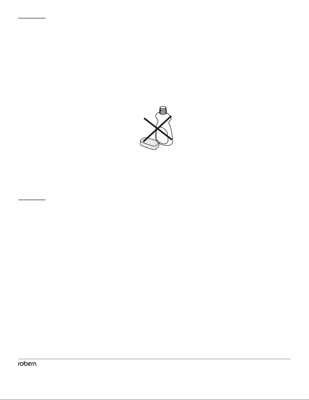
Use only a damp cloth to clean. Ammonia or vinegar-based cleaners can damage the nish.
A 50/50 solution of water and isopropyl alcohol is recommended for cleaning the light xture.
When cleaning, spray the cloth, not the light xture or surround surfaces. Do not use abrasive cleansers on any part of the light xture.
Limited Warranty One Year Term
Robern warrants to the original purchaser that, it will, at its election repair, replace, or make appropriate adjustment to products made
by this company shown to have signicant defects in material or workmanship which are reported to Robern in writing within one (1)
year from the date of delivery. Robern is not responsible for installation costs. The warranty is void in the event the product is damaged
in transit, or if damage or failure is caused by abuse, misuse, abnormal usage, faulty installation, damage in an accident, improper
maintenance, or any repairs other than those authorized by Robern. At the expiration of the one year warranty period, Robern shall be
under no further obligation under any warranty, expressed or implied, including the implied warranty of merchantability. Robern shall
not be liable for any consequential damages arising out of or in connection with the use or performance of its products. Some states
do not allow limitations on how long an implied warranty lasts or do not allow the exclusion or limitation of incidental or consequential
damages, so the above limitation or exclusion may not apply to you. Any liability against Robern under any implied warranty, including
the warranty of merchantability, is expressly limited to the terms of this warranty. Permission to return any merchandise under this
warranty must be authorized by Robern and returned prepaid by the purchaser. Claims under this warranty should be sent directly to
your dealer.
©2020 Robern, Inc.
All rights reserved
No Ammonia
Sans Ammoniac
Sin Amoniaco
No Vinegar
Sans Vinaigre
Sin Vinagre

No. de pièce / Pieza n.°209-1329 03/25/20
Lampe Vesper Midline, Outline / Iluminación Vesper Midline, Outline
15
© 2020 Robern, Inc. 701 N. Wilson Ave. Bristol, PA 19007 U.S.A.
800.877.2376 www.robern.com
Instructions d'installation / Instrucciones de instalación 15
Cette che d'instructions contient des informations sur
l'installation du Vesper Midline ou de Vesper Outline Light.
Cette série se décline en plusieurs variantes. Veuillez vous
référer à la boîte ou à l'étiquette du produit pour le numéro de
modèle spécique. Une clé est fournie à la page 16.
Conservez ces instructions pour une utilisation et une
référence futures. Une installation incorrecte annule la
garantie. Inspectez soigneusement la lampe pour tout
dommage. Les produits installés ne peuvent pas être
retournés.
Si vous rencontrez des problèmes avec votre éclairage,
contactez votre revendeur ou directement Robern.
Garantie limitée - Durée d'un an
Esta hoja de instrucciones contiene información sobre cómo
instalar Vesper Midline o Vesper Outline Light. Esta serie
viene en muchas variaciones. Consulte la caja o la etiqueta
del producto para obtener el número de modelo especíco. Se
proporciona una clave en la página 16.
Guarde estas instrucciones para uso futuro y referencia.
Una instalación incorrecta anula la garantía. Inspeccione
cuidadosamente la luz en busca de daños. Los productos
instalados no pueden ser devueltos.
Si tiene algún problema con su luz, comuníquese directamente
con su distribuidor o con Robern.
Garantía limitada: un año
CONTENU CONTENIDO
INFORMATION GÉNÉRALE INFORMACIÓN GENERAL
LAMPE VESPER™ MIDLINE / OUTLINE
Instructions d'installation
Consignes de sécurité importantes - Conserver ces instructions
ILUMINACIÓN VESPER™ MIDLINE / OUTLINE
Instrucciones de instalación
Instrucciones de seguridad importantes - Guarde estas instrucciones
Assemblage des supports - 19
Montage des supports sur l'armoire - 20
Accéder au boîtier électrique - 21
Installation de récréation - 22
Installation en surface - 23
Assemblée finale - 25
Montaje de los soportes - 19
Montaje de los soportes en el gabinete - 20
Acceda a la caja eléctrica - 21
Instalación de recreo - 22
Instalación de montaje en superficie - 23
Asamblea final - 25
Convient aux emplacements humides /
Adecuadas para ubicaciones húmedas

No. de pièce / Pieza n.°209-1329 03/25/20
Lampe Vesper Midline, Outline / Iluminación Vesper Midline, Outline
16
© 2020 Robern, Inc. 701 N. Wilson Ave. Bristol, PA 19007 U.S.A.
800.877.2376 www.robern.com
Instructions d'installation / Instrucciones de instalación 16
Robern recommande d'utiliser le gradateur Maestro® C • L® de
LUTRON®, modèle MACL-153M.
http://www.lutron.com/TechnicalDocumentLibrary/369613a.pdf
D'autres gradateurs de commande à LED peuvent fonctionner avec
ce produit mais n'ont pas été testés ou vériés. Il est recommandé de
laisser le variateur à la portée de votre miroir an de pouvoir régler la
luminosité.
Pour un fonctionnement tout ou rien (sans gradation), un interrupteur
mural standard peut remplacer le gradateur.
Utilisez le tableau ci-dessous pour savoir comment lire le numéro
de modèle de votre lampe. Ce tableau fait référence au numéro de
modèle pour une lampe Midline Light de 2,75 "L x 40" H avec une
nition en métal argenté. Consultez le catalogue de prix Robern pour
obtenir une liste complète des numéros de modèle.
Para los modelos regulables, Robern recomienda el Atenuador
Maestro® C • L® de LUTRON®, Modelo # MACL-153M.
http://www.lutron.com/TechnicalDocumentLibrary/369613a.pdf
Otros atenuadores de control LED pueden funcionar con este producto
pero no han sido probados o vericados. Se recomienda que el
atenuador esté al alcance de su espejo para que pueda ajustar el
brillo.
Para la operación de encendido / apagado (sin atenuación), se puede
sustituir un interruptor de pared estándar en lugar del atenuador.
Use la tabla a continuación para aprender a leer su número de modelo
de luz. Este cuadro hace referencia al número de modelo para una
luz de línea media de 2.75 "de ancho x 40" de alto con un acabado de
metal plateado. Consulte el Libro de precios de Robern para obtener
una lista completa de los números de modelo.
RECOMMANDATIONS AU
GRADATEUR
NUMÉROS DE MODÈLE
RECOMENDACIONES DEL
INTERRUPTOR DE ATENUACIÓN
NÚMEROS DE MODELO
Numéros de modèle / Números de modelo G L B 40 M L S S 3D
Gamme de produits / Línea de producto G = Vesper
L = Lumières / Luces
B = 2-3/4" / 70 mm
30 = 30" / 762 mm
36 = 36" / 914 mm
40 = 39-3/8" / 1000 mm
M = Midline
U = Outline
L = LED
3 = 3000K
S = Lampe simple / Sola lámpara
D = Dimmable / Regulable
S = argent / Plata
Nom de lumière / Nombre de luz
Largeur / Anchura
Quantité de lampes / Cantidad de lámparas
Type de moteur / Tipo de motor
Catégorie / Catégorie
Type de lampe / Tipo de lámpara
Température de couleur / Temperatura del color
la taille / Altura
Couleur principale du corps / Color del cuerpo principal
No. de pièce / Pieza n.°209-1329 03/25/20
Lampe Vesper Midline, Outline / Iluminación Vesper Midline, Outline
17
© 2020 Robern, Inc. 701 N. Wilson Ave. Bristol, PA 19007 U.S.A.
800.877.2376 www.robern.com
Instructions d'installation / Instrucciones de instalación 17
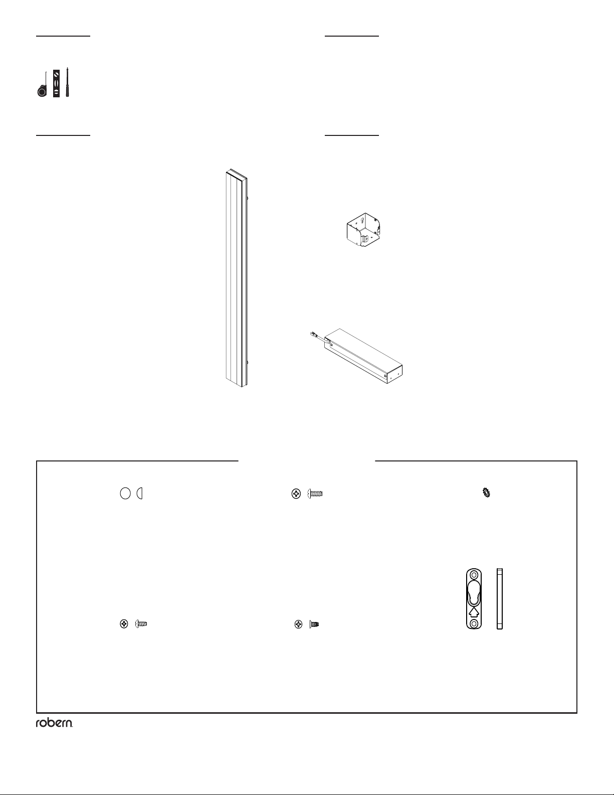
OUTILS NÉCESSAIRES HERRAMIENTAS NECESARIAS
PIÈCES PIEZAS
[210-1709]
(2) Supports de montage /
Soportes de montaje
(1) Midline/Outline
Lumière / lámpara
[205-3176]
(1) Boîtier électrique / Caja eléctrica
* Selon l'installation, toutes les pièces ne seront pas utilisées /
Dependiendo de la instalación, no se utilizarán todas las piezas.
[SS672]
(6) Chapeau à vis /
Tapapernos
210-1661
(4) Mounting Brackets
(1) Midline/Outline
Lights
216-1197
(1) Hardware Bag
216-1195
(1) Hardware Bag
(2) Edgeline
Lights
SS672
(12) #10 Screw Cap
203-1068
(3) #8 Lock Washer
SS344
(2) Screw, #8 x 3/8"
203-1497
(9) Screw, #8 x 3/8" Flat
SS676
(8) Screw, #10 x 1/2"
SS675
(4) Screw, #10 x 3"
211-1362
(4) Button Receiver
211-1351
(1) Mounting Button
219-1076
(1) Cable Tie Holder
203-1089
(1) Cable Tie, 4"
(1) Electrical Enclosure
205-3176
(1) Electrical Enclosure
210-1709
(2) Mounting Brackets
SS672
(6) #10 Screw Cap
SS676
(4) Screw, #10 x 1/2"
SS344
(2) Screw, #8 x 3/8"
203-1068
(3) #8 Lock Washer
203-1497
(5) Screw, #8 x 3/8" Flat
211-1362
(2) Button Receiver
211-1351
(1) Mounting Button
[SS676]
(4) Vis / Tornillo, #10 x 1/2"
[203-1497]
(4) Vis / Tornillo, #8 x 3/8" Flat
[SS344]
(2)Vis / Tornillo, #8 x 3/8"
[203-1068]
(2) #8 Rondelle de blocage /
Arandela de seguridad
[211-1362]
(2) Récepteur Bouton /
Receptor de Botón
210-1661
(4) Mounting Brackets
(1) Midline/Outline
Lights
216-1197
(1) Hardware Bag
216-1195
(1) Hardware Bag
(2) Edgeline
Lights
SS672
(12) #10 Screw Cap
203-1068
(3) #8 Lock Washer
SS344
(2) Screw, #8 x 3/8"
203-1497
(9) Screw, #8 x 3/8" Flat
SS676
(8) Screw, #10 x 1/2"
SS675
(4) Screw, #10 x 3"
211-1362
(4) Button Receiver
211-1351
(1) Mounting Button
219-1076
(1) Cable Tie Holder
203-1089
(1) Cable Tie, 4"
(1) Electrical Enclosure
205-3176
(1) Electrical Enclosure
210-1709
(2) Mounting Brackets
SS672
(6) #10 Screw Cap
SS676
(4) Screw, #10 x 1/2"
SS344
(2) Screw, #8 x 3/8"
203-1068
(3) #8 Lock Washer
203-1497
(5) Screw, #8 x 3/8" Flat
211-1362
(2) Button Receiver
211-1351
(1) Mounting Button
Sac de visserie / Bolsa de herrajes*
[CB-216-1197]
No. de pièce / Pieza n.°209-1329 03/25/20
Lampe Vesper Midline, Outline / Iluminación Vesper Midline, Outline
18
© 2020 Robern, Inc. 701 N. Wilson Ave. Bristol, PA 19007 U.S.A.
800.877.2376 www.robern.com
Instructions d'installation / Instrucciones de instalación 18
REMARQUES NOTAS
DANGER -
RISQUE DE CHOC -
DÉBRANCHEZ
L'ALIMENTATION AVANT
L'INSTALLATION
PELIGRO -
RIESGO DE CHOQUE -
DESCONECTE LA
ALIMENTACIÓN ANTES DE
LA INSTALACIÓN
Déballez la lumière. Vériez soigneusement la boîte pour tout le
matériel et les pièces détachées. Inspectez soigneusement le
luminaire pour tout dommage.
DANGER: Risque de blessures corporelles. Pour
éviter un éventuel choc électrique, l'électricité doit être coupée au
niveau du disjoncteur ou de la boîte à fusibles avant de tenter toute
procédure d'installation.
DANGER: Risque de blessures corporelles. Pour
éviter tout choc électrique, le luminaire doit être correctement mis à la
terre.
ATTENTION:Instructions de mise à la terre
pour les produits connectés en permanence: Ce produit doit être
connecté à un système de câblage permanent métallique mis à la terre
ou un conducteur de mise à la terre de l'équipement doit être exécuté
avec les conducteurs du circuit et connecté à la borne de mise à la
terre de l'équipement ou au l du produit. Tout le câblage doit être
effectué par un électricien agréé qualié.
IMPORTANT: l'alimentation des lumières doit être fournie séparément
de l'électricité à l'armoire an que lorsque les lumières sont éteintes,
l'électricité de l'armoire reste allumée.
REMARQUE: Nécessite un circuit d'au moins 120 VCA 15 ampères.
REMARQUE: Nécessite un gradateur compatible approuvé pour
l'installation (non inclus). Reportez-vous à la recommandation du
gradateur à la page 16.
Respectez tous les codes électriques et codes du bâtiment
applicables. Câblez les luminaires conformément aux codes
électriques.
Ce luminaire est destiné à une utilisation en intérieur uniquement.
Cette installation peut nécessiter l'assistance de plusieurs personnes
en fonction de la conguration de votre éclairage / armoire.
Desempaca la luz. Revise la caja a fondo para ver todos los
accesorios y piezas sueltas. Inspeccione cuidadosamente el accesorio
por daños.
PELIGRO: Riesgo de lesiones personales. Para
evitar posibles descargas eléctricas, la electricidad debe apagarse
en el disyuntor o en la caja de fusibles antes de intentar cualquier
procedimiento de instalación.
PELIGRO: Riesgo de lesiones personales. Para
evitar posibles descargas eléctricas, el artefacto de iluminación debe
estar debidamente conectado a tierra.
PRECAUCIÓN: Instrucciones de
conexión a tierra para productos conectados permanentemente:
este producto debe conectarse a un sistema de cableado metálico
permanente conectado a tierra o un conductor de conexión a tierra del
equipo debe funcionar con los conductores del circuito y conectado
al terminal de conexión a tierra del equipo o al cable del producto.
Todo el cableado debe ser realizado por un electricista calicado y con
licencia.
IMPORTANTE: la alimentación de las luces debe proporcionarse por
separado de la electricidad al gabinete, de modo que cuando las luces
se apagan, la electricidad del gabinete permanece encendida.
NOTA: Requiere un circuito mínimo de 120 VCA y 15 amperios.
NOTA: Requiere un atenuador compatible aprobado para la instalación
(no incluido). Consulte la recomendación de dimmer en la página 16.
Observe todos los códigos eléctricos y de construcción aplicables.
Cablee las lámparas de acuerdo con los códigos eléctricos.
Este accesorio es solo para uso en interiores.
Esta instalación puede requerir la asistencia de más de una persona
dependiendo de la conguración de su Light / Cabinet.

No. de pièce / Pieza n.°209-1329 03/25/20
Lampe Vesper Midline, Outline / Iluminación Vesper Midline, Outline
19
© 2020 Robern, Inc. 701 N. Wilson Ave. Bristol, PA 19007 U.S.A.
800.877.2376 www.robern.com
Instructions d'installation / Instrucciones de instalación 19
ÉTAPE 1 - ASSEMBLAGE DES
SUPPORTS
PASO 1 - MONTAJE DE LOS
SOPORTES
Remarque: Une installation RH (main droite) nécessitera de
retourner le boîtier électrique, en plaçant le l basse tension
sortant plus près du support supérieur.
1. Orientez l'un des supports de montage [210-1709] (comme illustré)
en vous assurant que les vis d'accès électrique sur le boîtier électrique
[205-3176] sont dirigées vers l'avant de l'armoire.
2. Fixez le boîtier électrique inclus (205-3176) au support à l'aide des
vis n ° 8 [SS344] et des rondelles frein [203-1068] fournies.
Nota: Una instalación RH (mano derecha) requerirá que la caja
eléctrica se voltee, colocando el cable de bajo voltaje que sale
más cerca del soporte superior.
1. Oriente uno de los soportes de montaje [210-1709] (como se
muestra) asegurándose de que los tornillos de acceso eléctrico en el
gabinete eléctrico [205-3176] apunten hacia el frente del gabinete.
2. Fije el gabinete eléctrico incluido (205-3176) al soporte utilizando
los tornillos # 8 suministrados [SS344] y las arandelas de seguridad
[203-1068].
SS344 SS344
203-1068 203-1068
210-1709
205-3176 205-3176
Les onglets font
toujours face à la
boîte de l'armoire
/ Las pestañas
siempre se en-
frentan a la caja
del gabinete
Les onglets font
toujours face à la
boîte de l'armoire
/ Las pestañas
siempre se en-
frentan a la caja
del gabinete
Installation de LH / Instalación de LH
210-1709
Électrique
vis d'accès /
Eléctrico
tornillos de
acceso Connexion laire
basse tension /
Conexión de cable
de baja tensión
Installation de RH / Instalación de RH
Électrique
vis d'accès /
Eléctrico
tornillos de
acceso
Connexion laire
basse tension /
Conexión de cable
de baja tensión
Électrique
vis d'accès /
Eléctrico
tornillos de
acceso
Électrique
vis d'accès /
Eléctrico
tornillos de
acceso

No. de pièce / Pieza n.°209-1329 03/25/20
Lampe Vesper Midline, Outline / Iluminación Vesper Midline, Outline
20
© 2020 Robern, Inc. 701 N. Wilson Ave. Bristol, PA 19007 U.S.A.
800.877.2376 www.robern.com
Instructions d'installation / Instrucciones de instalación 20
ÉTAPE 2 - MONTAGE DES SUP-
PORTS SUR L'ARMOIRE
PASO 2 - MONTAJE DE LOS
SOPORTES AL GABINETE
Remarque: ne serrez pas complètement les vis. Cela permettra
des ajustements dans les étapes ultérieures.
1. Montez les supports sur l'armoire à travers les emplacements de
regroupement, comme illustré, à l'aide des vis # 10 fournies [SS676].
Nota: No apriete completamente los tornillos. Esto permitirá
realizar ajustes en pasos posteriores.
1. Monte los soportes en el gabinete a través de las ubicaciones
de agrupamiento, como se muestra, utilizando los tornillos # 10
suministrados [SS676].
SS676
SS676
This manual suits for next models
3
Table of contents
Other Robern Personal Care Product manuals


Popular Personal Care Product manuals by other brands

Philips
Philips HeartStart Home owner's manual

sensiplast
sensiplast 291821 Instructions for use

Dr. Kern
Dr. Kern Skinfresh Tancan 3000 Assembly and operating instruction

ConvaTec
ConvaTec ESTEEM + Soft Convex How to use

Allard
Allard Elements Body User instruction

microbeau
microbeau Spektra Xion S user manual

Pulsaderm
Pulsaderm Buddy quick start guide

HoMedics
HoMedics spa REFLECTIVES M-8006 Instruction manual and warranty information

Remington
Remington REVEAL MAN1000 manual

ergoline
ergoline Genesis Classic 650 owner's manual

Philips
Philips sonicare AirFloss Ultra instructions

VANITY PLANET
VANITY PLANET Raedia user guide


