Robertshaw SlimZone Premier User manual

ZONE CONTROL SYSTEM
INSTALLATION AND OPERATION MANUAL

SlimZone Premier i
TABLE OF CONTENTS
1. INTRODUCTION.............................................................................................................................1
1.1 IMPORTANT NOTE....................................................................................................................................1
1.2 FEATURES.................................................................................................................................................1
1.3 SAFETY INSTRUCTIONS..........................................................................................................................2
2. APPLICATION AND DESIGN CONSIDERATIONS........................................................................2
3. COMPONENT REQUIREMENTS...................................................................................................3
3.1 BASIC SYSTEM ........................................................................................................................3
3.2 EXPANDER MODULE...............................................................................................................3
3.3 ENVIRONMENTAL MODULE....................................................................................................4
3.4 SIZING TRANSFORMERS........................................................................................................4
3.5 SIZING DAMPERS ....................................................................................................................4
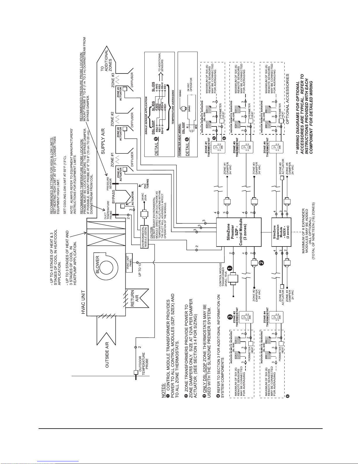
3.6 TYPICAL SYSTEM DIAGRAM...................................................................................................4
4. SYSTEM INSTALLATION................................................................................................................6
4.1 SLIMZONE PREMIER CONTROL MODULE (SZP)..................................................................................6
4.1.1 REMOVAL AND INSTALLATION OF THE DOOR .........................................................................6
4.1.2 INSTALLATION OF THE BACKPLATE..........................................................................................6
4.2 THERMOSTAT INSTALLATION: DSL-520P...............................................................................................7
4.3 DAMPERS..................................................................................................................................................7
4.4 WIRING INFORMATION..........................................................................................................................10
4.5 CURRENT LIMITED OUTPUT TERMINALS...........................................................................................10
4.6 SLIMZONE ENVIRONMENTAL MODULE (SZEM)..................................................................................11
5. SYSTEM OPTIONS AND OPERATION........................................................................................12
5.1 INTERACTION BETWEEN MODULES ...................................................................................................12
5.1.1 SZP CONTROL MODULE............................................................................................................12
5.1.2 DSL-520P ZONE THERMOSTAT.................................................................................................13
5.1.3 SZEM ENVIRONMENTAL MODULE ...........................................................................................14
5.2 SYSTEM PROGRAMMING......................................................................................................................14
5.2.1 PROGRAMMING FEATURES .....................................................................................................14
5.2.2 SCHEDULES................................................................................................................................14
5.2.3 FACTORY DEFAULTS .................................................................................................................15
5.3 USER OPTIONS......................................................................................................................................15
5.4 HVAC OPTIONS.......................................................................................................................................15
5.5 CONTROL METHODS.............................................................................................................................16
5.5.1 TIMESHARE.................................................................................................................................16
5.5.2 DIFFERENTIAL............................................................................................................................16
5.6 SEQUENCE OF OPERATION.................................................................................................................17
5.6.1 TIMESHARE MODE.....................................................................................................................17
5.6.2 DIFFERENTIAL MODE................................................................................................................18
5.7 USER INTERFACE ..................................................................................................................................18
5.7.1 LCD SYMBOL DESCRIPTION.....................................................................................................18
5.8 FLOW DIAGRAM .....................................................................................................................................19

ii SlimZone Premier
6. START UP AND TEST...................................................................................................................22
TROUBLESHOOTING GUIDE...............................................................................................................26
GLOSSARY ............................................................................................................................................27
APPENDIX A: LIST OF FIGURES........................................................................................................28
APPENDIX B: LIST OF TABLES ..........................................................................................................28
ZONE SCHEDULE.................................................................................................................................29
ZONE DIAGRAM....................................................................................................................................30
WARRANTY ...........................................................................................................................................31

SlimZone Premier 1
1. INTRODUCTION
The SlimZone Premier (SZP) is a commercial/residential HVAC (Heating/Ventilation/Air
Conditioning) zone control system which allows control of up to nineteen (19) zones with a
single HVAC system. Each zone is controlled by its own zone thermostat and motorized
damper. The control module monitors the zone thermostats, sets the HVAC system in the
appropriate mode of operation, and energizes the number of stages of heating or cooling
accordingly.
The basic system consists of the main SlimZone Premier control module (SZP-3) which may
control up to three (3) zones. The modular nature of this system allows the expansion of the
number of controlled zones by simply adding SlimZone Expander modules (SZEX) which add
two (2) zones to the system per module. Up to eight (8) expander modules may be connected
to the control module, allowing a total of nineteen (19) zones.
Only DSL-520P communicating zone thermostats may be used with the SlimZone Premier
Control module. Each zone to be controlled requires a zone thermostat.
The user interface to the SlimZone Premier consists of a four (4) button keypad and a four (4)
line by twenty (20) character LCD display, through which all system information may be viewed
or modified.
1.1 IMPORTANT NOTE
IT IS IMPORTANT THAT YOU READ AND UNDERSTAND THIS MANUAL SUPPLIED WITH
THE SLIMZONE PREMIER, AS WELL AS THE HVAC EQUIPMENT MANUFACTURER’S
INFORMATION, BEFORE BEGINNING INSTALLATION OF THE SYSTEM.
1.2 FEATURES
•Ultra slim styled cabinet (8-7/8" (22.5cm)W x 9-1/2" (24cm)H x 1-3/4" (4.5cm)D)
•Two (2) modes of operation: timesharing or differential
•Four (4) lines by twenty (20) characters backlit LCD display
•User friendly interface which allows access to features such as:
- panel setup
- system programming (temperatures, schedules, 2 or 4 events per day)
- 12 or 24 hour clock
- temperature display in °F or °C
- equipment test
•LED (light emitting diode) status indicators on all system functions
•Solid state control module with current limited relay outputs
•Controls heat pumps, cooling units and gas, oil or electric furnace units
•Number of controlled zones expandable to nineteen (19) in increments of two (2) zones by
ordering the SlimZone Expander module (SZEX)
•Controls up to four (4) stages of heating and three (3) stages of cooling in heat/cool mode
•Controls up to three (3) stages of heating and three (3) stages of cooling in heat pump mode
•Two (2) speed fan output
•Forty-five (45) second fan purge into last zone(s) calling
•Constant or automatic fan during occupied cycle
•Two (2) or three (3) wire damper capability
•Perimeter heat control from zone thermostats
•High/Low limit downstaging
•High/Low balance control

2SlimZone Premier
•Minimum on/off times (short cycle protection)
•Occupied/unoccupied cycle capability
•Manual or automatic changeover
•Smoke detector input
•All low voltage wiring
•No batteries required
1.3 SAFETY INSTRUCTIONS
•Sudden equipment operation may cause serious injury from moving parts. Leave power
disconnected until installation is complete.
•Sharp edges may cause damage to wires. Use care during the installation.
•Installation must be done in accordance with all applicable codes and regulations.
•Installer should touch a grounded metal object before handling any of the modules in the
SlimZone Premier control system, to avoid potential loss of internal computer programs due to
static discharge.
2. APPLICATION AND DESIGN CONSIDERATIONS
A. Only DSL-520P communicating zone thermostats may be used.
B. Air conditioning control systems require that the air handling equipment be properly sized for
the application; otherwise, satisfactory temperature control may not be realized.
C. It is recommended that system installations be limited to thirty (30) tons of equipment capacity.
Enerstat dampers are designed to work only with low pressure systems (1.0" WC or less).
D. Oversizing of HVAC equipment is not recommended. In most cases it is better to slightly
undersize than oversize.
E. Extra consideration should be given in applications that require large amounts of cooling in cold
weather, such as buildings with a center or core area.
F. At least two (2) stages of cooling and/or compressor unloading are highly desirable.
G. Hot gas bypass should be considered on some commercial systems.
H. If the HVAC unit is supplied with an economizer, it is recommended that the economizer
package be equipped with a relief air damper.
I. The pressure drop across typical dampers is negligible and normally is not a factor when sizing
or calculating branch duct CFM.
J. Balancing dampers should be installed ahead of all motorized zone dampers.
K. Zone dampers should be installed ten (10) feet back from discharge grille when possible.
L. Flex or lined duct is recommended on the last five (5) feet.
M. A bypass damper must be installed on all systems of three (3) zones or more.
N. The thermostats and motorized dampers may be located up to 300 feet (90m) from the control
module, using nonshielded 3 (dampers) and 4 (thermostat) conductor 18 - 24AWG copper
wires.
O. A maximum load of 2.5 Amps may be switched by the output terminals, which complies with
Class 2 wiring code.
P. System wires should be tagged to match the module terminal designations.
Q. The addition of equipment heating and cooling limits, as provided by the SlimZone
Environmental module (SZEM), is strongly recommended and will greatly help in preventing
temperature swings as well as constant heating/cooling changeover.

R. All zones served by a SlimZone control module should have the same basic load characteristics
(i.e., do not put 4 zones on an east exposure, and the 5th zone on a southwest exposure).
S. All references to typical dampers refer to Enerstat model dampers.
T. Zones 14-19 adhere to the same schedule and act as a single call for equipment. Although they
are separate physical zones they act as a single zone when communicating with the SZP
Control module. It is recommended that when considering the layout of your zone system,
zones 14-19 should be assigned to areas of low priority.
3. COMPONENT REQUIREMENTS
3.1 BASIC SYSTEM
The basic system consists of the main SlimZone Premier Control module (SZP-3: 3 zone
module) and its supporting components.
ITEM QUANTITY CONSIDERATIONS
SZP-3 control module one (1) contains three (3) zones
DSL-520P zone thermostat one (1) per zone use standard nonshielded 4
conductor 18-24AWG copper wire
Motorized zone dampers one (1) per zone (minimum) use standard nonshielded 3
conductor 18AWG copper wire
24VAC transformers one (1) for main module 75VA
zone dampers powered by refer to section 3.4 for sizing
separate transformer(s)
Table 3.1: SlimZone Premier Basic Components
3.2 EXPANDER MODULE
Each SlimZone Expander module (SZEX) consists of two (2) additional zones. For each
expander module added, the following items are required:
ITEM QUANTITY CONSIDERATIONS
SZEX expander module one (1) contains two (2) zones
DSL-520P zone thermostat one (1) per zone use standard nonshielded 4
conductor 18-24AWG copper wire
Motorized zone dampers one (1) per zone (minimum) use standard nonshielded 3
conductor 18AWG copper wire
24VAC transformers SZEX powered by SZP N/A
zone dampers powered refer to section 3.4 for sizing
by separate transformer(s)
Table 3.2: SlimZone Expander Module Components
Note: Expander module itself does not require a transformer as it is powered by the control
module.
SlimZone Premier 3

4SlimZone Premier
3.3 ENVIRONMENTAL MODULE
ITEM QUANTITY CONSIDERATIONS
SZEM environmental module one (1) contains two (2) remote temperature
probes, and PVC tubing for static
pressure
use standard nonshielded 2
conductor 18-24 AWG copper wire
to connect to SZP
Motorized bypass damper one (1) - may require two (2) use standard nonshielded 3
in larger systems conductor 18AWG copper wire
24VAC transformer one (1) 20VA (300mA)
Table 3.3: SlimZone Environmental Module Components
3.4 SIZING TRANSFORMERS
To avoid unsatisfactory operation DO NOT power the SZP control module with the HVAC
equipment transformer. A dedicated field supplied 24VAC, 75VA transformer is recommended
to power the control module, which in turn may have up to nineteen (19) zones connected to
it. Zone dampers require separate transformers.
Zone dampers may be powered by individual zone transformers or by a single transformer. A
single transformer used to power more than one damper must have a sufficient power rating
(VA) to energize all dampers. To determine the total power requirements, add each damper’s
VA rating. Typical dampers require a maximum of 12VA each. This total must not exceed the
VA rating of the transformer.
3.5 SIZING DAMPERS
It is important that dampers be sized according to system ductwork specification (CFM) and
balanced in compliance to SMACNA, ACCA and ASHRAE guidelines in order for the control
system to properly control comfort in each zone. Typical dampers are nonmodulating and are
available in two (2) wire (powered closed, spring return to open), or three (3) wire (powered
closed, powered open) configuration. The pressure drop across Enerstat dampers is negligible
and normally not a factor when sizing or calculating branch duct CFM. Typical dampers are
designed to work with low pressure systems (1.0" WC) or less.
3.6 TYPICAL SYSTEM DIAGRAM
Figure 3.1 illustrates a typical SlimZone Premier installation, including the optional
environmental module (SZEM) and its accessories.

Figure 3.1: Typical System Diagram
SlimZone Premier 5
AND ACCESSORIES.
OPTIONAL ACCESSORIES.

6SlimZone Premier
4. SYSTEM INSTALLATION
4.1 SLIMZONE PREMIER CONTROL MODULE (SZP)
4.1.1 REMOVAL AND INSTALLATION OF THE DOOR
Installer should touch a grounded metal object before handling the control panel to avoid
potential loss of programming due to static discharge.
NOTE:
The door is hinged on the left side.
Open the door by gently pulling on the bottom right corner, applying finger pressure only. The
door may be removed once opened by applying a slight backward pressure. Replace the door
by hooking around the tabs on the left side of the backplate and snapping back into place.
4.1.2 INSTALLATION OF THE BACKPLATE
The control module can be mounted on any interior surface. Use the mounting holes on the
backplate of the main unit and the two (2) mounting holes on the expander modules (if so
equipped) to secure using the supplied #8 screws (Figure 4.1). Mount the control module in a
location that provides easy access for service. Do not mount the control module on any part
of the HVAC equipment or where moisture may be present. There are several round holes and
knock-outs for through-the-wall or surface wiring.
CAUTION: Use proper care when removing upper or lower end cap knock-outs. Apply a
sharp rap with the butt end of a screwdriver to remove. Do not use sharp instruments to
remove the knock-outs as internal damage may occur.
SZP-3 SHOWN WITH ONE
EXPANDER MODULE (SZEX)
Figure 4.1: Mounting Holes

4.2 THERMOSTAT INSTALLATION: DSL-520P
LOCATION
The most important consideration in installing your DSL-520P Communicating Zone thermostat
is where to locate the unit. The location can radically affect the operation of the thermostat.
To ensure proper operation, the thermostat should be mounted on an inside wall in a frequently
occupied area of the zone. In addition, its position must be at least 18 inches (46cm) from any
outside wall, and approximately 5 feet (1.5m) above the floor in a location with freely circulating
air of an average temperature. The control module has four (4) terminals at each zone terminal
strip for connecting the thermostat.
CAUTION: Ensure that the following polarity is respected (refer to Figure 4.2):
DSL-520P.......SZP
1..................... 1
2..................... 2
3..................... 3
4..................... 4
Refer to the manual provided with the DSL-520P thermostat for detailed instructions.
4.3 DAMPERS
Typical dampers are designed to work with low pressure systems (1.0" WC or less). Balancing
dampers should be installed ahead of all zone dampers. Zone dampers should be installed
10ft. (3m) back from discharge grille. A flex or lined duct is recommended for the last 5ft.
(1.5m). Enerstat dampers are nonmodulating dampers. Two (2) wire dampers are powered
closed and spring return open. Three (3) wire dampers are powered closed and powered open.
For applications requiring minimum air ventilation, an adjustment screw is available to set the
damper to a specified minimum open position. Enerstat dampers are shipped from the factory
with the minimum position adjustment screw in the fully closed position; allow for a 3% to 5%
leakage with damper closed. The control module has five (5) terminals at each zone terminal
strip for damper connections which are as follows (refer to Figure 4.2):
24L: 24VAC transformer, 24N: 24VAC transformer common
PC: power damper closed 24N: common
PO: power damper opened
Power to the dampers is provided by the 24L and 24N terminals at each zone terminal strip.
Refer to section 3.4 for information on sizing transformers.
High ambient temperatures that may be encountered (in an attic for instance), will have an
impact on the current capabilities of the panel and the number of zone dampers that can be
connected to the panel. The SZP is powered by a single 75VA transformer. This transformer is
used to power the panel and thermostats. The ambient temperature will have an impact on the
polyfuse current limiting protection. The maximum number of dampers that can be connected
per zone using Enerstat dampers are:
At 25°C (77°F) At 40°C (104°F)
5 E Series dampers 4 E Series dampers
4 E2 Series dampers 3 E2 Series dampers
5 E3 Series dampers 4 E3 Series dampers
If additional dampers are required you must use a relay to energize these additional
dampers from an independent source.
SlimZone Premier 7

8SlimZone Premier
Figure 4.2: SZP Wiring Diagram

SlimZone Premier 9
EMERGENCY

10 SlimZone Premier
4.4 WIRING INFORMATION
Use #18AWG (nonshielded) copper wire for all system wiring; thermostats may use 18-24AWG
wire. Thermostats and damper actuators may be located up to 300ft. (90m) from the control
module. All system wires should be tagged to identify thermostat, damper and equipment
wiring. Refer to Figure 4.2 for control module wiring diagram. It is strongly recommended that
a spare or third wire be run between the control module and each zone damper in the event
that a three (3) wire damper actuator is used or required in future.
4.5 CURRENT LIMITED OUTPUT TERMINALS
All output circuits on the SlimZone Premier control module incorporate self-resetting current
limiting devices which provide protection against excessive current draws caused by
circumstances such as wiring shorts on an output. These devices, referred to as polyfuses,
generally are activated when the current draw exceeds 2.5Amps. The value and the duration
of the excess current is taken into account. The polyfuses will allow excess currents of very
short duration (i.e., spikes) in order to prevent circuit interruptions by noisy lines or occasional
minor surges. In its current limiting mode, the polyfuses reduce the output current to milliamps.
NOTE: The low leakage current may be sufficient to produce a small voltage reading when
measured with a volt meter with a high input impedance.
When the cause of the excess current has been removed and the current draw is returned to a
value below 2.5Amps, the polyfuse will reestablish full output current; in some instances this
may take up to twenty (20) seconds. Polyfuses eliminate the need to replace blown fuses.
The SZP control module uses red LEDs to indicate when a problem exists with the current
being drawn from certain circuits. An LED exists for the following on-board circuits:
•each zone damper circuit
•each zone thermostat circuit (current limited @ 0.1Amp)
•on the COOL terminal strip
•on the HEAT terminal strip

4.6 SLIMZONE ENVIRONMENTAL MODULE (SZEM)
INTRODUCTION
The SlimZone Environmental module (SZEM) is an
optional component in the SlimZone Premier system. The
module provides the following services:
•Bypass damper control and static pressure sensing
•High/Low temperature limit signaling
•Outdoor temperature measurement
DATA EXCHANGE
All information collected by the SZEM module is communicated to the SlimZone Premier
control module (SZP) via a RS485 communication port at 1200 baud. All information received
by the SZP control module may be viewed by the user (Figure 5.2).
BYPASS SYSTEM
In order to maintain proper air flow and static pressure throughout the HVAC system, a bypass
system should be used. In some 2-zone applications, a bypass damper may not be required.
This is based on duct sizing where either zone is able to handle approximately 75% of the total
system CFM (cubic feet/minute). This will result in only slightly higher air velocity at the
discharge grille if only one zone is calling and yet allow for proper CFM across the cooling coil.
A single zone fan call may cause some air noise in large systems. If any single zone is unable
to handle the remaining 25%, the minimum air adjustment in the closed zones must be set to
accommodate the excess air. Single zone calls for equipment (fan, heating or cooling), may
cause air noise and/or temperature overshoot in large systems. This is the result of excess air
being discharged through the zone diffuser. When this occurs it is recommended that the user
select a similar call from an additional zone in order to alleviate the amount of air going to the
single zone call.
Note: This situation can occur when the SZP Control module is in the auto fan mode or when
a single heating or cooling call occurs from Must-Service zones.
Bypass activities are fully controlled by the SZEM module which monitors the system static
pressure and modulates a motorized bypass damper accordingly. The static pressure value is
communicated to the SZP control module.
HIGH AND LOW TEMPERATURE LIMITS
When bypassing conditioned air it is important to consider high and low limit control to prevent
coil freeze up or overheating. The SZEM module monitors the conditioned air temperature and
signals the SZP control module when the high and low limits are exceeded. System air
temperature value is communicated to the SZP control module.
OUTDOOR TEMPERATURE MEASUREMENTS
In heat pump applications, the outdoor temperature may be used to determine when to lock
out either the compressor(s) or auxiliary heat (high and low balance points). Outdoor air
temperature is communicated to the SZP control module. Outdoor temperature value may be
displayed at both the SZP control module and zone thermostats. Refer to the information
provided with the SZEM module for detailed installation instructions.
SlimZone Premier 11

12 SlimZone Premier
5. SYSTEM OPTIONS AND OPERATION
5.1 INTERACTION BETWEEN MODULES
The SZP control module is the central processing unit in the SlimZone Premier system and is
in constant communication with the DSL-520P zone thermostats and the optional SlimZone
Environmental module (SZEM). The following describes the interaction between the modules.
5.1.1 SZP CONTROL MODULE
The control module has global control of the system and establishes parameters such as
program temperature setpoints, schedules, and mode of operation.
EQUIPMENT CONTROL
The control module has full control of the HVAC equipment. It processes the zone requests for
heating, cooling, and fan and monitors the conditions reported by the SZEM module and
services the zones accordingly.
TESTING
All relay output terminals may be tested from the SZP control module via the Equipment Test
menu. All zone dampers may be activated as well as all zone perimeter heat relays. Bypass
dampers may also be tested from the control module.
PROGRAMMING
All system programming is done at the SZP control module. The module establishes the
temperature setpoints and the events the zone thermostats control. Temporary local override
is made possible by changing the setpoints at the zone thermostats. Refer to section 5.2 for
further programming information.
MODE OF OPERATION (Off, Cool, Heat, Auto, E Heat)
The control module establishes the global (system) mode of operation; local mode of operation
may be selected at the zone thermostats. Only calls for the modes established by the control
module will be serviced.
CONSTANT FAN
Global fan control is established at the control module. When set to constant fan (fan on) and
the system is idle, all zone dampers are opened to circulate air to all zones. When the global
fan control is set to auto, local requests for constant fan are serviced; dampers to zones not
calling for constant fan are closed. The G1 terminal is used for constant fan. Refer to section
5.4 for Smart Fan feature.
MINIMUM EQUIPMENT ON AND OFF TIMES (Short Cycle Protection)
Minimum equipment ON and OFF times are set at the control module for both heating and
cooling. Zone thermostats also have minimum ON time settings (2 or 4 minutes). The control
module ensures the equipment is not shut off until the thermostat and the module minimum ON
times have elapsed; timers run concurrently. Minimum OFF time is established by the control
module.
DATA EXCHANGE: SZP CONTROL MODULE / DSL-520P ZONE THERMOSTAT
The SZP control module provides the following information to the DSL-520P thermostats:
•temperature setpoints
•event (morning, day, evening, or night)
•time of day
•outdoor temperature (if SZEM module is installed with this option)

The DSL-520P thermostat provides the following information to the SZP control module:
•heating, cooling, and fan requirements
•room temperature
•temperature setpoints (if temporary local override is requested)
DATA EXCHANGE: SZP CONTROL MODULE / SZEM MODULE
The SZP control module provides the following information to the SZEM module:
•high and low temperature limits
The SZEM module provides the following information to the SZP control module:
•outdoor temperature
•duct temperature and pressure
•status of high and low limits
5.1.2 DSL-520P ZONE THERMOSTAT
The DSL-520P zone thermostat provides local control of the following parameters:
MODE OF OPERATION
Local mode settings are requests only; calls for these modes are serviced only if the control
module is in that mode as well.
PERIMETER HEAT
When the SZP control module is unable to service a zone requesting heating because it is
currently servicing cooling or in a minimum OFF time, the thermostat will close its relay contact
on terminals R and W1 which may be used to energize a local perimeter heat device. When the
module is finally able to provide heating, perimeter heat will be disabled.
NOTE:
- Perimeter heat is allowed only when the control module is in the heat or auto mode.
- The perimeter heat relay is a 24VAC dry contact output (rated at 0.75Amps).
CONSTANT FAN
When global constant fan is selected, all zones are in the constant fan mode regardless of the
local fan setting. The fan () symbol appears on the thermostat display when local constant
fan is selected; it does not appear when global constant fan is selected.
TEMPORARY TEMPERATURE OVERRIDE
During the occupied period, individual zone temperature setpoints may be changed and remain
valid for the duration of the occupied period. The temporary setpoints are discarded when the
thermostat changes over to the unoccupied period (minimum one (1) hour).
During the unoccupied period, individual zone temperature setpoints may be changed and
remain valid for a period of one (1) hour, after which the temporary setpoints are discarded.
UNOCCUPIED MODE: SYSTEM & LOCAL
System:
Unoccupied Mode: Unoccupied mode occurs when all zone thermostats are in night mode.
Local:
Unoccupied Mode: Unoccupied mode occurs when a zone thermostat goes into night mode.
The minimum temporary override is (1) one hour and will remain in effect until the (1) one hour
period has elapsed. Moving into an unoccupied period (night mode) during this minimum
temporary override will not affect its status.
During the unoccupied period, zones 1 to 13 act as Must-Service zones when the zone
thermostat or buttons (system override) are depressed. Zones 14 to 19 do not act as
Must-Service zones at this time.
SlimZone Premier 13

14 SlimZone Premier
MINIMUM EQUIPMENT ON TIME (short cycle protection)
The minimum amount of time the thermostat will call for heating or cooling may be set to either
2 or 4 minutes via switch #1 on the back of the thermostat. This timer is initiated the moment
the request is made, regardless if the control module services the demand immediately. When
equipment is activated, it will not shut off until both the thermostat’s and the SZP control
module’s minimum ON times have elapsed; timers run concurrently.
The thermostat has no minimum OFF time setting.
CLOCK DISPLAY FORMAT
Time may be displayed in either 12 or 24 hour format. Press and hold the FAN button, then
press the OUTDOOR button to change the format.
TEMPERATURE DISPLAY FORMAT
The temperature may be displayed in either °C or °F format. Press the and buttons
simultaneously to change the format.
5.1.3 SZEM ENVIRONMENTAL MODULE
The SZEM module monitors the system ductwork pressure and controls a motorized bypass
damper accordingly. The module also monitors the ductwork air temperature and signals the
SZP control module when the high and low limits have been exceeded. The SZEM module can
also be installed with an outdoor temperature probe. The outdoor temperature is
communicated to the SZP module.
5.2 SYSTEM PROGRAMMING
All system programming is done at the SZP control module.
5.2.1 PROGRAMMING FEATURES
The SlimZone Premier system offers the following programming features:
•7day programmable
•2or 4 events per day (morning, day, evening, night)
•individual zone schedules
- zones 1 - 12 may have unique schedules
- zones 13 - 19 use the same schedule
•copy a day schedule to consecutive days or to all days of the week
•copy a zone program to other zones
5.2.2 SCHEDULES
The SZP control module can execute the schedules as follows:
NORMAL:
The control module executes the programmed schedules normally.
SUSPENDED: PERMANENTLY
When this mode is selected, the programmed schedules are disregarded and the user must
enter override temperature setpoints to which all zone thermostats will be controlling. Local
override is still allowed but for a duration of one (1) hour (unoccupied mode). The system will
remain in the PERMANENTLY SUSPENDED mode until the user changes it.
SUSPENDED: TEMPORARILY (UNTIL)
When this mode is selected, the programmed schedules are disregarded and the user must
enter override temperature setpoints to which all zone thermostats will be controlling. The time
and date when the system is to return to the NORMAL mode also must be entered. Local

override is still allowed but for a duration of one (1) hour (unoccupied mode). The system will
remain in the TEMPORARILY SUSPENDED mode until the programmed time and date is
reached.
5.2.3 FACTORY DEFAULTS
The SZP control module is shipped with the following program settings:
•All temperature setpoints set at:...Heat: 68°F(20°C) Cool: 73°F(23°C)
•All schedule times set at:..............12:00A
5.3 USER OPTIONS
The SZP control module allows the user to set the time of day display in 12 or 24 hour format.
The user also may set the temperature display in Celsius or Fahrenheit. These settings do not
affect the thermostat displays.
5.4 HVAC OPTIONS
The SZP control module allows the installer to establish the following system parameters:
HEAT/COOL OR HEAT PUMP SYSTEM
The SZP module can control up to four (4) stages of heating and three (3) stages of cooling in
the heat/cool mode and three (3) stages of heating and three (3) stages of cooling in the heat
pump mode.
In the heat pump setup, W3 terminal is used for the auxiliary heat, even when a single
compressor is used. The emergency heat mode becomes available as one of the modes of
operation. When emergency heat is selected, W3 terminal will cycle on demands for heating
and W4 terminal will be on continuously.
NUMBER OF STAGES OF HEATING AND COOLING AND NUMBER OF ZONES REQUIRED
TO ACTIVATE EACH STAGE
Upstaging and downstaging is based strictly on the number of zones calling. Downstaging will
also occur when the high and low limits are exceeded.
MINIMUM HEATING AND COOLING ON AND OFF TIMES
The system allows input of different minimum ON and OFF times for heating and cooling.
CONTROL METHOD: TIMESHARE OR DIFFERENTIAL
The SZP control module has two methods of determining which equipment calls to service first
(heating or cooling) and when to changeover to the opposite equipment. The two control
methods, timesharing and differential, are described in section 5.5.
THE MUST-SERVICE ZONE
The Must-Service zone uses an intelligent weighting protocol which gives a status to the zone
such that a call from this zone equals the number of zones required to activate the first stage
of that mode. For example, if three (3) zones are required to call for activating first stage
heating, a call from the Must-Service zone will be given a weight of three (3) to simulate three
(3) zones calling. From this point, the control module will process this call and determine if the
zone is to be serviced based on the timesharing or differential control methods. The Must-
Service zone is not given any other special status.
HIGH AND LOW TEMPERATURE LIMITS
The limits are entered at the SZP control module and stored in the SZEM module memory.
HIGH AND LOW BALANCE POINTS
These values are used to determine when the auxiliary heat terminal should be disabled (high
balance point) and when the compressor terminal should be disabled (low balance point).
SlimZone Premier 15

16 SlimZone Premier
SMART FAN ENABLE
When Smart Fan is enabled and constant fan is selected at the control module (global constant
fan), the fan will remain ON during the occupied period and go to the auto mode during the
unoccupied period. Note that all zones have to be in the unoccupied (night) period for the fan
to go in the auto mode. If auto fan is selected at the control module, local fan demands are
processed normally; fan will be ON to zones requesting constant fan.
5.5 CONTROL METHODS
5.5.1 TIMESHARE
The timeshare control method will change over from heating to cooling and vice versa as
follows:
A. No equipment calls are serviced until the number of zones calling for either heating or
cooling meet the requirements for the number of zones needed to activate first stage. The
first mode to satisfy the requirements will be serviced.
B. Upon initiating the equipment call, the control module starts a 20 minute internal timer.
Calls for the opposite equipment mode are ignored during these 20 minutes.
C. If the current call is not satisfied after the first 20 minutes and calls for the opposite
mode have met the requirements to activate the first stage of equipment, the control
module will changeover to the opposite mode and reinitiate the 20 minute timer.
NOTE:
-In heat/cool mode, the control module will changeover to the opposite equipment
mode after the minimum OFF time of the equipment it just serviced.
-In heat pump mode, changeover is done by activating the opposite reversing valve
output (O/B terminals); the compressor is not turned OFF.
D. The control module will continue in this fashion, changing over every 20 minutes, until the
zones are satisfied. Note that the control module will service an equipment call only if the
number of zones calling meet the requirements to activate that stage. The moment the
number of zones calling is not sufficient to activate that stage, the module will consider
this call to be satisfied.
UPSTAGING AND DOWNSTAGING
When the control module changes over to the opposite equipment mode and sufficient number
of zones are calling for second stage, the module will start with the first stage. If after 5 minutes
the number of zones calling is still sufficient, the module will activate the second stage.
Subsequent stages are activated, one every 5 minutes, providing the number of zones calling
is sufficient. In the heat pump mode, the auxiliary heat is delayed a further 15 minutes after the
last compressor stage.
Downstaging occurs in a similar manner when the number of zones calling decreases to a value
below the number of zones required to activate that stage.
5.5.2 DIFFERENTIAL
In the differential control method, the control module determines the difference between the
number of zones calling for heating versus the number of zones calling for cooling. The
difference calculated is then compared to the number of zones required to activate the first
stage of equipment for the mode which has more calls, and if sufficient, that stage will be
activated and zones calling for that mode will be serviced.
UPSTAGING AND DOWNSTAGING
If the calculated difference between zone calls is sufficient to activate the second stage of
equipment for the mode currently activated, then the module will upstage. Downstaging occurs
when the number of zones calling decreases and the calculated difference falls to a value below
the number of zones required to activate that stage.

5.6 SEQUENCE OF OPERATION
5.6.1 TIMESHARE MODE
Note: The following assumes the control module is in the auto mode of operation.
A. Control module receives zone requests for heating and cooling. First mode to satisfy the
number of zones requirement for first stage is serviced.
B. Equipment is activated:
- W1 is energized for heating and Y1 is energized for cooling (in both heat/cool and heat pump
mode).
- B terminal is energized for heating and O terminal is energized for cooling.
- Both G1 & G2 fan terminals are energized.
- Dampers to zones calling for that mode are open.
- 20 minute timer is initiated.
C. Equipment stays ON for at least minimum ON time.
D. In the heat pump mode, if the 20 minute timer runs out and the opposite mode is being
requested, the control module will changeover to the opposite mode (timesharing) by toggling
the reversing valve output terminals (O and B). The compressor is not turned OFF.
E. When the equipment call is satisfied (in both heat/cool and heat pump mode), or when the 20
minute timer has elapsed and the opposite mode is being requested (in heat/cool mode), the
equipment is turned OFF and a 45 second purge cycle begins:
- W1 or Y1 is deenergized.
- G2 is deenergized; G1 remains energized.
- B or O terminal remains energized.
- Zone dampers remain open.
F. After the 45 second fan purge, the equipment will remain OFF for at least the duration of the
minimum OFF time for the equipment which was just serviced. The control module will remain
in one of the following conditions during this period:
- If global constant fan selected, all zone dampers open and G1 remains ON to circulate air.
- If only local constant fan is requested, dampers to zones requesting constant fan open and
all other dampers close. G1 remains ON.
- If constant fan not requested and no other equipment calls are present, G1 is deenergized and
dampers to last zones calling remain open.
- If constant fan is not requested and calls for the opposite mode of equipment are received by
the module, G1 is deenergized and dampers to the zones calling for the opposite mode are
open and all other dampers are closed.
G. After the minimum OFF time, the control module will service the opposite mode of equipment
if calls for it are pending; steps Ato Eare repeated. If there are no pending calls for the
opposite mode, the control module is ready to service any calls.
NOTES:
•When changing over to the opposite mode of equipment, the control module will start with
the first stage of equipment even if enough zones are calling to activate additional stages.
The module will upstage every five (5) minutes afterwards; auxiliary heat stage in the heat
pump mode will energize fifteen (15) minutes after the last compressor stage.
SlimZone Premier 17
This manual suits for next models
3
Table of contents
Other Robertshaw Control System manuals
Popular Control System manuals by other brands

Lippert Components
Lippert Components OneControl HVAC Control 2.0 owner's manual

Vicon
Vicon NOVA V1400 installation manual

Cattron
Cattron CommandPro 23 Series user manual

Ingeteam
Ingeteam INGECON SUN EMS Board Installation and configuration

BFT
BFT STOPPY MBB 219-500.C Instructions for installation, use and maintenance

Hardi
Hardi HC 2500 Series Instruction book