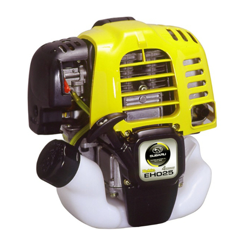
Robin EC05-2 User manual


ROBIN
AMERICA, INC.
ROBIN
TO
WISCONSIN
ROBIN
ENGINE
MODEL
CROSS REFERENCE
LIST
ROBIN
EY08
EY15
EY15V
EY20
EY2OV
EY23
EY28
EY3
5
EY40
-
EY45V
EY2
1
EY44
EY18-3
EY25
EY27
EH11
EH12
EH15
EH17
EH21
EH25
EH30
EH30V
EH34
EH34V
EH43V
EC13V
DY23
DY27
DY30
DY3
5
DY41
WISCONSIN
ROBIN
SIDE
VALVE
W
1-080
W1-145
W1-145V
W1-185
W1-185V
W1-230
W 1-280
W
1-340
W 1-390
Wl-45OV
EY21W
EY44W
EY18-3W
EY25W
EY27W
OVERHEAD
VALVE
WO1-115
wo1-120
WO1-150
WO1-170
wo1-210
WOl-250
WO 1-300
WO1-300V
WO1-340
WO
1
-340V
WO 1-43OV
TWO CYCLE
WT1-125V
DIESEL
WRD
1-230
WRD
1-270
-1-300
WRD1-350
WRD1-410
0
0
0

CONTENTS
Section
Title
Page
1
.
SPECIFICATIONS
...........................................
1
2.
PERFORMANCE
............................................
2
2.1
.
MaximumOutput
.......................................
2
2.2
.
ContinuousRated Output
..................................
2
2.3
.
MaximumTorque andFuelConsumptionRatio
at
Max
.
Output
........
2
3
.
FEATURES
................................................ 5
4
.
GENERALDESCRIPTION
of
ENGINECONSTRUCTION
................
6
4.1
.
4.2
.
4.3
.
4.4
.
.
4.5
.
4.6
.
4.7
.
4.a
.
4.9
.
4-1
0
.
4-11
.
4-1
2
.
4-13
.
4.14
.
4-15
.
SectionalView of Engine
..................................
6
Crankcase
.............................................
14
Baseplate
.............................................
14
CrankshaftandConnecting
Rod
Assy
..........................
14
Piston
...............................................
14
DrivingShaft (for Model B only)
.............................
15
Cylinder
..............................................
15
Cylinder Head (Model EC10.17.2
5.2
only)
......................
15
Governor
..............................,...............
15
Cool'ing
..............................................
15
Ignition
..............................................
15
Carburetor
............................................
16
Air Cleaner
............................................
16
ReductionEquipment
(for
Model
B
only)
.......................
16
StartingPulleyorRecoilStarter
.............................
16
5
.
INSTALLATION
.............................................
17
5.1
.
Mounting
.............................................
17
5.2
.
Ventilation
............................................
17
5.3
.
Exhaust
Gas
Evacuation
...................................
17
5.4
.
Fuel System
...........................................
17
5.5
.
PowerTransmission to Drive Machines
.........................
17
5.6
.
Wiring
...............................................
18
6
.
DISASSEMBLY
and
REASSEMBLY.
...............................
20
6.1
.
PreparationsandSuggestions
................................
20
6.2
.
Special Tools
..........................................
22
6.3
.
Disassembly
and
ReassemblyProcedure
........................
24
7
.
MAGNETO
................................................
29
7.1
.
Magneto.
..............
;
..............................
29
7.2
.
Breaker PointAdjustment
..................................
29
7.3
.
TimingAdjustment
......................................
30
7.4
.
Magneto TroubleShooting
.................................
31
8
.
GOVERNOR
...............................................
32
8.1
.
Construction and Operation
................................
32
8.2
.
GovernorAdjustment
....................................
34
8.3
.
High Speed Adjustment
...................................
36
9
.
CARBURETOR
.............................................
38
9.1
.
Construction and Operation
................................
39
9.2
.
DisassemblyandReassembly
................................
39
9.3.
Adjustments
...........................................
41
10
.
RUN-IN
OPERATION
of
REASSEMBLED ENGINE
....................
42
I1
.
TROUBLESHOOTING
........................................
43
11.1
.
Starting Difficulties
......................................
43
11.2
.
Slow-Speed
out
of
order
...................................
44
11.3
.
Overheatingand Knocking
.................................
44
11.4
.
Power Drop
...........................................
45
11
.5
.
Excessive FuelConsumption
................................
45
11.6
.
Engine Hunting
.........................................
45
11.7
.
OtherComplaints
.......................................
45
12
.
CHECKS and CORRECTIONS
...................................
46
13
.
MAINTENANCE and STORING
..................................
53
0
13.1
.
Daily ChecksandMaintenance
..............................
53
13.2
.
Every 50Hours
(10
Day) ChecksandMaintenance
.................
53
13.4
.
Every
500-600
Hours(Semiannual) ChecksandMaintenance
.........
53
13.6
.
Preparation for LongAbeyance
..............................
54
13.3
.
Every
100-200
Hours (Monthly) ChecksandMaintenance
...........
53
13.5
.
Every
1000
Hours
(Yearly)ChecksandMaintenance
...............
54

.-
1.
SPECIFICATIONS
1
0
0
'4
c
.
f
Lo
5-
0
m
00
Lo
0
9
.
ln
T
c
a
P
a
-1-

2.
PERFORMANCE
2-1
MAXIMUM OUTPUT
The maximum output
of
an
engine is such standard power as developed by that engine, after its initial run-in period withall
the movingparts properlyworn-in,whenoperatingwith thefullyopenthrottle valve. Therefore,itfollowsthata new
engine may notdevelopthismaximum output in the beginning,becausemovingpartsarenot inaproperlyworn-in
condition.
2-2
CONTINUOUSRATEDOUTPUT
Thecontinuous rated output
of
anengine
is
suchpower asdevelopedby that enginewhenrunning at an optimum speed
most favorable from the point
of
viewof engine life and fuel consumption ratio. Therefore, it follows that when designing a
driving
system
for
anymechanism, with a model
EC05-2,07-2,
IO,
17
or
25-2
engine, as a prime mover, the continuous pow-
errequirement
of
that mechanism must
be
kept below the continuous rated outputspecified.
2-3
MAXIMUMTORQUE
and
FUELCONSUMPTIONRATIOATMAX.OUTPUT
The maximum torque of an engine is that driving torque
of
the driving shaft at which the engine is driving an external load,
while the engine is developing its max. output. The fuel consumption ratio at max. output is that fuel consumption ratio
of
an engine while that engine is running at the max. output.
PERFORMANCE CURVE
MODEL
EC05-2D
I
for
B
tvoe
HP
2500 3000 3500'
4000
4500
5000 5500
(910) (1090) (1270) (1460)(1640) (1820) (2000)
0.4
(1.09)
0.3
(0.82)
t
-2-

PERFORMANCECURVE
MODEL EC07-2D
( )
for
B
type
HP
t
4
3
HP
t
2
1
0
PERFORMANCE CURVE
MODELECIOD
(
)for
B
tj
(1000)(1200)(1400)(1600)
(1800)
(2000)
-
rpm
-3-

HP
HP
t
PERFORMANCECURVE
kg-m
PERFORMANCECURVE
MODEL EC25-2DS
kg-m
-4
-
__c
rpm

3.
5.
4.
5.
6.
*-
.
7.
8.
9.
FEATURES
COMPACT, LIGHT WEIGHT, HIGH PERFORMANCE
and
LOW
FUELCONSUMPTION.
TROUBLE FREE
because of simpledesign and easy
to
handle.
HIGH DURABILITY
engine withstand long severe operation.
TILTED OPERATION
available.
As
a
special feature
of
2-cycle engine, can operate at up
to
about
30'
tilted position just before the
fuel
flooding out
from the air-bent
of
carburetor.
EASY STARTING
Recoil type starter
is
available at option.
LIGHTING
for night operation.
Optional lightingis available by installing special lighting coil.
Lighting
Capacity:
EC05-2,07-2
(1
2V
-
16V,
6W)
..
EC10,17(6
-
8V,
15W)
EC25-2 (1'2V,
18
-
25W)
VERSATILE APPLICATION
Direct,or reduction type engine with horizontal shaft orvertical shaft are available.
Wide selection
of
driving shaft size and shapes are also available beside standard specification.
Further,consultwith dealer for smallerfuel tank,heavy-dutyfilterelementfor air cleanerandhigh-performance
muffler.
The engine can control
to
the desired speed with a
ALL-SPEED GOVERNOR.
It can. be set
for
any desired speed
by
simply moving the controllever.
The
setting speed
is
maintained even under vary-
ing
load.
-
Engine withstand
AGAINST HIGH VIBRATION
environment.

4.
GENERALDESCRIPTION
of
ENGINECONSTRUCTION
4-1
SECTIONAL
VIEW
of
ENGINE
FUEL TANK CAP
\
MUFFLERCOVER
7
\I
MUFFLER
GOVERNOR
CONTROLLEVER
MODEL EC05-2,07-2
-6-

FUEL
TANK
PISTON PIN
BLOWER
HOUSING
FLYWHEEL
STARTING
PULLEY
NlTlON
COIL
MODEL'EC05-2.07-2
I.

CYLINDER
7
\
MUFFLER COVER-
\
FUEL TANK CAP
r
FUEL TANK
GOVERNORARM
MODEL
ECIO
CLEANER
ETOR
'ER
-8-


CYLINDE
CYLINDER
\
MUFFLER
f
FUELTANK
MODEL
EC17
:LEANER
-10-

1
1,
MODEL
EC17
-
11
-

00
00
00
00
00
00
00
00
00
00
00
00
00
00
00
MUFFLER-
MODELEC25-2
-
12-

P.
T
7
FUEL
TANK
SPARKPLUG
CYLINDER HEAD7
.BLOWERHOUSING
-COOLINGFAN
. IGNITION COIL
.STARTING PULLEY
,FLYWHEEL
-CRANKSHAFT
MODEL
EC25-2
-13-

4-2
CRANKCASE
All partsrelated with crankcase assy arealuminium alloy diecastings,which removed all unnecessary excess thickness for
extreme lightness, consist
of
split-type front crankcase, rear crankcase and crankcasecover (for Model
D)
or reduction cover
(for Model B) depending upon the modelas per the following table,
Model Reduction
Cover
Crankcase Cover Rear Crankcase
Front Crankcase
EC05-2
D
B
B
Exclusive for
D
D
Exclusivefor
B
Exclusivefor
B
for
D
type
~
EC07-2 for
D
type Exclusive for
B
Exclusivefor
B
D
Exclusivefor
D
Exclusive for
D
-
EC10 for
D
type Exclusive for
B
B
~
v
Exclusive for
D
Exclusive for
D
D
Exclusive for
D
Exclusive for
V
~-
EC17 for
D
type Exclusive for
B
/
Exclusivefor
B
B
v
Exclusive for
D
Exclusivefor
V
I
EC25-2
D
for
DS
type
DS
for
D
type Exclusivefor
D
Exclusivefor
D.DS
Model EClOD,
V.
EC17D,
V.
EC25-2D.
DS:
The rear crankcaseformsa governor chamberand provided with crankcase cover.As front, rear crankcase coverhasoneballbearing respective-
ly,
thecrankshaft
is
supported by
3
ball bearings.
Model
EClOB,
EC17B
The rearcrankcase forms
a
part of the reduction gear chamber and after installing the reduction gear and governor, reduction cover
is
to
be
fitted.
The
reductioncover has two ball bearings, one
is
supporting the crankshaft and the other one
is
supporting the driving shaft.
4-3
BASE PLATE
Thebaseplatemade
of
aluminumalloydiecasting is to beattached
to
thefrontandrearcrankcase.with
4
bolts.
4-4
CRANKSHAFT
and
CONNECTINGROD ASSY.
Thecrankshaft is separable intothefrontcrankshaft,rearcrankshaftandcrankpin.
Crankshaftismade
of
forgedcarbon steel;Crankpin is made
of
chromium-molybdenumsteel,hardenedand
precision machined.
Connectingrod is aforged chromium-molybdenumpiecewhich is equippedwith needle-bearings at both large and
small ends.Bothrodends hasan oilgrooves
to
deliver lubricant to preventburningandwearing.
Thefront, rear crankshafts and the crankpinareassembledtogetherandforcefittedinexactalignmentwiththe
specialassemblingfixtureafterfittedtheneedle-bearingandconnectingrod onthe crankpin.Generally, they can
notdisassembled.In case
of
replacing thecrankshaft,it is requested
to
replacecrankshaftandconnectingrodin
assembled manner.
4-5
PISTON
The piston is made of precision-casted heat-resistant aluminum alloy which machined precisely into oval section in order to
prevent from burning and slapping. It is attached to the connecting rodsmall end by means
of
a piston and a needle bearing.
Near the top of the piston, there are two grooves for compressionrings. In order to prevent the rotating therings during the
operation and damagingthe cylinder port, lock-pins are inserted.
-
14-

4-6
DRIVING
SHAFT
(P.T.O.
shaft)
(for
Model B
only)
The driving shaft is made
of
forged carbon steel and reduction gear
is
force-fitted.
4-7 CYLINDER
‘Model
EC05-2,EC07-2
Monoblockcylinderandcylinderhead .is made
of
aluminum alloy diecastingand-insidethecylinder is treatedwith
hard-chromium plating
to
withstand against the wear by reciprocal motion
of
the piston.
Outsidefins
of
cylinder-headarearranged to getefficientheatdispersionand providedwiththreaded holeformountinga
spark plug on the top.
Inside thecylinder,oneeachofintakeport,exhaustport and two scavenging portsarepositionedto get themaximum
engine performance.
-.
Model
ECIO,EC17
The cylinder is made
of
precision-casted wear-resistant cast iron provided with fins for perfect heat dispersion.
Inside thecylinder,oneeach
of
intake
port,
exhaustportandtwo scavenging portsarepositioned to get themaximum
engine performance.
The cylinder is attached
to
the crankcase with the flange, which positioned lower part of cylinder, by stud-bolts.
*Model
EC25-2
The cylinder
with
the cylinder liner
is
made of aluminium alloy. The cylinder liner
is
made of special cast iron and are
im-
bedded
in
the
aluminium casting as inserts. Inside the cylinder, one each
of
intake port, exhaust port and four scavenging
ports are positioned
to
the maximum engine performance.
4-8
CYLINDER HEAD
(Model
ECIO,
17,25-2
only)
Thecylinderhead is made
of
heat-conductivealuminumalloyand is providedwith the fins,arrangedinthedirection
of
cooling air to achieve the efficient cooling.
The combusion chamber forms semi- spherical andis provided with threaded hole for mounting a spark-plug on the top.
4-9 GOVERNOR
The centrifugal flyweight type governor assures constantspeed operation at selected speed, irrespective
of
load fluctuations.
(The governor is built-in the crankcase for Model
EC05-2,07-2)
As
to the detail, refer to section
“8.
GOVERNOR”.
4-10COOLING
Thecooling fanwhich also serves asa flywheelforcilyfeeds cooling air to the cylinderandcylinderheadwith the aid
of
blower housing and air buffle.
4-11 IGNITION
The ignition system
is
of
flywheel magneto type with ignition timing set at
23”
before TDC
for
EC05-2, 07-2, 25-2, 18” be-
fore TDC for EC10 and
22”
before TDC for EC 17 respectively.
The flywheel with steel magnet piecerevolves outside thecoil and generates the electric power
in
the coil. The flywheel
also
equalize the engine revolution and at the same time,
it
serves as a blower, with its impellerson thecircumstance, for cooling
the
engine. The igntition coil andthebreaker are mounted
in
the crankcase.
As
to
the detail, refer to “Section
7.
MAGNETO”.
-15-

4-12
CARBURETOR
A
horizontaldraftfloattypecarburetor is employed.Itssettinghasbeencarefuilydeterminedafterthoroughtesting to
achieve best starting, accelerating, fuel consumption, output and performances.
As
to the detail suchas construction, refer
to
section
“9.
CARBURETOR”.
4-13
AIRCLEANER
Air
cleanerused inthismodel is asemi-wet type cleaner,whichcontainsoilsoakedfilteringelement thattraps all
dustparticlesfloating intheintake air
so
that cleanair is supplied tothecarburetor.
4-14
REDUCTIONEQUIPMENT
(For
Model
B
only)
With the Model B engine, rear crankcase and reduction cover forms the reduction chamber, and the revolution
of
crankshaft
reduced to 1/2.7for Model EC05-2, 07-2, to 1/25 for ModelEClOandEC17byreduction-gearandpinion, andthenits
transmitted to
P.T.O.
shaft. Governer is also equipped with reduction chamber and lubricated by same lubricant.
Use SAE
30
lubricant.
(for
EClO,
17)
4-15
STARTINGPULLEY
or
RECOILSTARTER
Optionalrecoilstarter is available for Model
D
and
B.
Model
V
is equippedwith recoil starter.
Starting pulley
of
Model
D
and
B
are identified according
to
the direction
of
engine rotation.
By removing the recoil starter, starting theengine can be made by starting pulley.
-
16-
This manual suits for next models
4
Table of contents
Other Robin Engine manuals

Robin
Robin EC12 User manual

Robin
Robin EH30V User manual

Robin
Robin Subaru EY15-3D User manual

Robin
Robin PKX201T User manual

Robin
Robin EH12-2D User manual

Robin
Robin EY35 User manual

Robin
Robin DY23-2D User manual

Robin
Robin EH12-2D User manual

Robin
Robin Subaru EY15-3D User manual

Robin
Robin EH12-2D User manual

Robin
Robin PKX301 User manual

Robin
Robin EC13V User manual

Robin
Robin EC03ER User manual

Robin
Robin EH12-2D/12-2B User manual

Robin
Robin EC06 User manual

Robin
Robin EC1O User manual

Robin
Robin EH11/W01-115 Operating instructions

Robin
Robin EY08D User manual

Robin
Robin EX35 User manual

Robin
Robin EX13D User manual