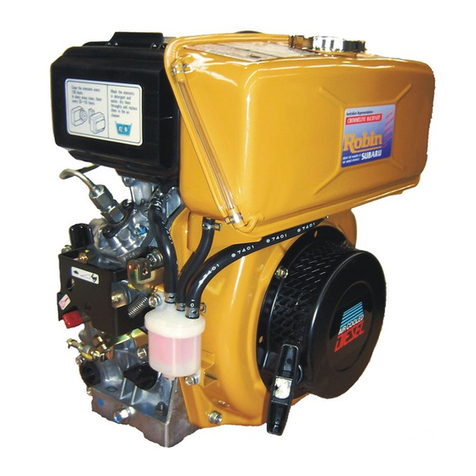
Robin EH30V User manual


ROBINAME
ROBIN
TO
WISCONSZN
ROBIN
ENGINE MODEL CROSS REFERENCE
LIST
ROBXN
EY 08
EY15
EY15V
EY20
EY20V
EY23
EY28
EY3
5
EY40
EY45V
EY2
1
EY44
EY18-3
EY25
EY27
EHll
EH12
EH15
EH17
EH2
1
EH25
EH30
EH3OV
EH34
EH34V
EH43V
EC13V
DY23
DY27
DY30
DY35
DY4
1
WISCONSIN
ROBIN
SIDE
VALVE
w
1-080
W1-145
w1-145v
W1-185
Wl-185V
W
1-230
W
1-280
W1-340
W
1-390
w
1
-450v
EY21
W
EY44W
EY25W
EY27W
EY
18-3
W
-
WO1-115
wo1-120
WQ1-150
WO1-170
wo1-210
WO 1-250
WO1-300
WO
1
-300v
WO
1-340
WO1-340V
WO1-43OV
TWO
CYCLE
WT1-125V
DZESEL
WRD1-230
WRD
1-270
WRD1-300
WRD1-350
WRD1-410

Section Title
ONTENTS
Page
1
.SPECIFICATIONS
......................................................................................
2JERFORMANCE
........................................................................................
2-
1
MaximumOutput
...............................................................................
2-2
MaximumTorqueAtMaximumOutput
..............................................
2-3
performance
curves
...........................................................................
3.
FEATURES
................................................................................................
4.GENERALDESCRIPTION OF ENGINECOMPONENTS.....
....................
4-
1
CylinderAndCrankcase
.....................................................................
4-2
~~i~~~~~i~~
cover
...........................................................................
4-3
Crankshaft
.........................................................................................
4-4
ConnectingRodAndPiston
.............................................................
4-5
Camshaft
...........................................................................................
4-6
ValveArrangement
.............................................................................
4-7
CylinderHead
....................................................................................
4-8
GovernorSystem
...............................................................................
4-9
CoolingSystem
..................................................................................
4- 10
Lubrication
.........................................................................................
4-
1
1
Ignition System
..................................................................................
4- 12
Carburetor
..........................................................................................
4- 13
Air Cleaner
.........................................................................................
4- 14
Balancers
............................................................................................
4- 15
Decompression System
......................................................................
1
2
2
2
2
4
4
4
4
5
5
5
6
6
6
7
7
8
8
8
9
9
4-
16
SectionalView Of Engine
..................................................................
10
12
12
12
13
28
42
42
42
43
5.DISASSEMBLY AND REASSEMBLY
......................................................
5-
1
PreparationsAndSuggestions
...........................................................
5-2
Special Tools
.....................................................................................
5-3
DisassemblyProcedures
.....................................................................
5-4
ReassemblyProcedures
......................................................................
6.MAGNETO
.................................................................................................
6-
1
FlywheelMagneto
..............................................................................
6-2
Basic Theory
......................................................................................
6-3
WiringDiagram
..................................................................................
7.AUTOMATIC DECQMPRESSlON SYSTEM
.............................................
44
8.CARBURETQR
...........................................................................................
45
45
46
48
48
52
8-
1
OperationAndConstruction
..............................................................
8-2
DisassemblyAnd Reassembly
....................
-
.......................................
g.STARTINGSYSTEM
................................................................................
9-
1
RecoilStarter
.....................................................................................
9-
2
Electric StartingMotor(Option)
........................................................
ECIFICATIONS
Model
Type
Bore
X
Stroke
PistonDisplacement
MaximumHorsepower
MaximumTorque
Rotation
Cooling
Lubrication
Lubricant
Carburetor
Fuel
Fuel Feed
GovernorSystem
IgnitionSystem
SparkPlug
LightingCapacity
StartingSystem
DryWeight
DimensionsWithout
P.T.0 Shaft
LXWXH
I
I
EH30V
EH34V
EH43V
1
I
Air-Cooled, 4- Cycle, VerticalShaft,Overhead Valve, GasolineEngine
78x61mm
(3.07
X
2.40
in.)
291cc
(1
7.76
cuin.)
9/3600
HP/rpm
(6.7/3600
KW/rpm)
1.95/2500
kg
*
m/rpm
14.1/2500ft.lbs/rpm)
84
X
61
mm
(3.31
X
2.40
in.)
338
cc
(20.63
cu.in.1
1 1
/3600
HP/rpm
(8.2/3600
KW/rpm)
2.41
/2500
kg m/rpm
17-4/2500
ft.lbs/rpm>
89x69
mm
(3.50
X
2.71
in.)
429
cc
(26.1
8
cu.in.1
13/3600
HP/rpm
(9.7/3600
KW/rpm)
2.85/2500
kg
m/rpn.
(20.6/2500
ft.Ibs/rpm
Counterclockwise
As
ViewdFromPTOShaft Side
ForcedAirCooling
Oil
PumpType Pressurised lubrication
withfullflowoilfiltel
Automobile Oil SAE
#
20,#
30
or
1
OW
-
30
HorizontalDraftType
AutomobileGasoline
GravityType
CentrifugalFlyweightType
FlywheelMagneto(SolidState)
NGK BP6ES (CHAMPION N9Y)
12V-2.5A/3000rpmBatteryCharge
RecoilStarter (Electric StarterOptional)
28
kg (61.7
I
bs.)
31
kg
(68.3
I
bs.)
386
X
383
X
327
mm
(1
5.20
X
15.07
X
12.88
in.)
410
X
401
X
349
mm
(1
6.1
4X
15.78X
13.74
in
Specificat[onsanddimensions are subject
to
changewithoutnotice.
-1-

2.
PERFORMANCE
2-1
MAXIMUM OUTPUT
The maximum output of anengine
is
such a standard power asproducedbytheenginewith
its
throttlevalvefully opened after
its
initialbreak-in period when allthemoving
parts
are
properlywornin.Therefore,a new enginemaynotproducethe maximum outputinthebeginning
because the moving partsare notin
a
properlyworn-in condition.
2-2
MAXIMUM TORQUE
The
maximum torqueindicatesthetorque
at
theoutputshaft when theengineisproducingthe
maximum output.
2
-
3
PERFORMANCE CURVES
EH30V
a
1
kg
-
m
REVOLUTION
r.
P.
m
-2-

0
EH34V
I
11
10
9
a:
g8
a
W
cn
a:
0
I
7
6
0
EH43V
13
a
I
It
l2
11
10
9
8
n
I
MAXIMUM
TORQUE
I
10
2000
2500
3000
3500
4000
L
REVOLUTION
-
I.
P.
m.
2.5
kg-
m
2.4
2.2
2.1
w
3
8
P
L
1500
2(
=
MAXIMUM
TORQUE
0
2500
3000
3500
REVOLUTION
-+
r.
P.
m.
-3-

3.
FEATURES
1.
Theoverheadvalvedesignofferscompactness,lightweightand ideal combustion charastristics
,"-,
resultingin morepower from less fuelandprolongedengine life.
2.
Thevibrationfreedesignwiththetwinbalancersystemandlighterreciprocatingparts.
3.
The
parts
suchasalargecapacitymuffler,dualelementair cleaner, helical typebalancergear
with extra longteethanda blower housingandmuffler covermade of resinlaminated
"DAMPING
SHEET"
reduce noise to
a
minimumlevel.
4.
Theautomaticdecompressionsystemofferseasy,dependablestarting.
5.
Themufflerandcarburatorare located on oppositesides,makingthearrangementsforcooling
air flowmuch easierinthedesign
of
power equipment.
4.
GENERALDESCRIPTION
OF
ENGINE COMPONENTS
4-1
CYLINDER AND CRANKCASE
Thecylinderandcrankcase
is
singlepiece
aluminumdiecasting.Thecylinderliner,made
of
special castiron, is molded intothe aluminum
casting.
Thecrankcasehasamountingsurfaceonthe
outputshaftside, where themainbearing cover
is
attached. (See Fig.
1.)
Fig.
I
4-2
MAIN
BEARING
COVER
The main bearing cover
is
an aluminum
diecasting, which
is
mountedon the outprt shaft
side of the crankcase. Remove the main bearing
cover
to
inspectinside
of
theengine.
The main bearing cover alsofunctionsasan oil
pan,with
a
trochoid oil pump,
oil
fillerand
oil
drainplug. (See Fig.
2.)
Fig.
2
-4-

4-
3
CRANKSHAFT
Thecrankshaft
is
forgedcarbonsteel,andthe
e
crankpinisinduction-hardened.Theoutput end
of theshafthasacrankshaftgearandbalancer
gear which arepressedintoposition.
(See Fig.
3.)
BALANCER GEAR
\
CRANKSHAFT
GEAR
Fig.
3
4-4
CONNECTING
ROD
AND
PISTON
Theconnectingrodisforgedaluminumalloy,
anditslargeandsmallendsfunctionas
bearings.Thepiston
is
an
aluminum -alloy
casting,andcarriestwocompressionrings and
one oil ring.(See
Fig.
4.)
Fig.
4
4-
5
CAMSHAFT
Thecamshaft
is
a hollow shapedand made
of
specialcastironwiththecamshaftgearcasted
together.
A .
cenerifugaldecompressionlever
is
assembled
on thecamshft.Thelubrication
oil
pump
is
driven
by
thepininstalled on theend
of
the
camshaft. (See
Fig.
5.)
Fig.
5
-5-

4-
6
VALVE ARRANGEMENT
Theintakevalve
is
located at flywheelside of
thecylinder head.
Hardalloyvalveseatsare molded in the
cylinderheadandstelliteisfused to the exhaust
valve face.
Thecylinderbaffleleads cooling air
to
the
exhaustvalveareafortheoptimum cooling.
(See Fig.
6.)
EXHAUST'VALVE
INTAKE
VALVE
Fig.
6
4-7
CYLINDER HEAD
Thecylinder head
is
analuminumdiecasting,
whichutilizes wedge typecombustionchamber
forthehighestcombustion efficiency.
(See Fig.
7.)
4-
8
GOVERNOR SYSTEM
Thegovernor
is
a centrifugalflyweighttype
which ensuresconstantoperation
at
the selected
speedagainst load variations.
Thegovernorgearwithgovernorweights
is
installedonthebearing cover anddrivenby
thecamshaftgear. (See Fig.
8.)
Fig.
7
Fig.
8
-6-

4-9
COOLING
SYSTEM
Thelargefins on the flywheelprovidesufficient cooling aircapacityforthe inletand exhaust
areaandcylinder.
a
Thecylinderbafflehelpsthecoolingair flow efficiently.
4-
10
LUBRICATION
Both EH30V(EH34V) and EH43V haveatrochoidpumpinsidethemainbearing cover thatis
driven by thecamshaft.
EH3OV and EH34V use forcedsplash
type
lubrication while thelarger EH43V employs apressurized
-lubrication which pressurelubricatesalltherotatingsurfaces of thecrankshaftandsupplies
oil to piston,cylinderandconnectingrod’ssmallendfromthe oil jet on crankshaft arm.
(See
Fig.
9.)
OIL FILTER
/
BEARING ,COVER
I
CAMSHAFT
Fig.
9
-7-

4-
1
1
IGNITION
SYSTEM
The ignition systemisatransistorcontrolled
magnetoignitionsystemwhichcosists of a
flywheel andanignition coil withabuilt in
transistormounted on thecrankcase.
Thissystemhas
an
ignitiontimingadvance
for
the easy starting. (See
Fig.
10.)
Fig.
10
4-
12
CARBURETOR
Theengines are equippedwithahorizontal
draftcarburetorthat has
a
floatcontrolled fuel
systemandafixedmain
jet.
Thecarburetorsarecalibratedcarefully
for
the
surestarting,
good
acceleration,
low
fuel
consumptionandsufficient output.
For
thedatails,refer
to
page
45,
section
"8
CARBURETOR".
(See Fig.
11.1
Fig.
1 1
4-
13
AIR
CLEANER
Theair- cleaner isaheavy-dutytypewitha
dualelementsystem. (See
Fig.
12.1
I
A
CLEANER BASE
I
ELEMENT
I
CAP
hUT
I
Fig.
12
-8-

4-
14
BALANCERS
Unbalanced inertiaforce is balanced
by
thetwo
balancerswhichrotateatthe samespeedwith
thecrankshafttoeffectivelyreducevibration.
(See
Fig.
13.)
I
BLANCER
4-
15
DECOMPRESSION
SYSTEM
An
automatic decompressionmechanismwhich
opensexhaustvalvebeforethepistonreaches
compression top is assembled on thecamshaft
foreasystarting. (See
Fig.
14)
Fig.
13
I
AUTOMATIC DECOMPRESSOR SYSTEM
*$
RETURN
SPRING
Fig.
14
-9-

4-
16
SECTIONAL
VIEW
OF
ENGINE
r
FLYWHEEL(COOLING FAN)
r
STARTINGPULLEY
I-
RECOIL STARTER
-
lo
-

BALANCERSHAFT
2
BALANCERSHAFT
1
CONNECTING
ROD
TMUFFLER
CAP
M
CARBURETOR
AIRCLEANER
OIL
FILTER
CAMSHAFT
-
11
-

5.
DISASSEMBLY
AND
REASSEMBLY
5-
1
PREPARATIONS AND SUGGESTIONS
1)
When disassembling theengine, memorize well the locations of individual parts
so
thatthey
can be reassembed correctly.
If
yor areuncertain
of
identifying
some
parts,
it
issuggested
thattags
be
attachedtothem.
2)
Have boxes readytokeep disassembed partsbygroup.
3)
To
preventmissingandmisplacing,temporarilyassembleeachgroup of disassembedparts.
4)
Carefullyhandledisassembed parts,and clean themwith washing oil
if
necessary.
5)
Use thecorrect tools inthecorrect way.
5-2
SPECIALTOOLS
Tool
No.
Use
Tool
209
-
95004
-
07
For
pulling off the flywheel
Flywheelpuller with
bolt
228
-
95003
-
07
Forplacing piston ring
Pistonring compressor
PISTON
RING
COMPRESSOR
/
FLYWHEEL
PULLER
Fig.
15
-
12
-

5-
3
DISASSEMBLY PROCEDURES
Part
to remove
Oil
drain
Procedures
Tool
Remarks
Remove
oil
drain plug and drain oil.17mm
Box
wrench
Be
carefulnot to
lose
the gasket.
Fuel tank
(1)
Turn
off fuel shut
-
off valve
and
(2)
Fuel shut-off valve and fuelline.
lOmm
Box
wrench
removefuel
tank.
6
d
X
~OITUII
Bolt
*.**--**
2pcs.
6
4
X
35m
Bolt
*-.-..*.
1
pce.
I
6
+
BOLT
AND
WASHER
Fig.
I6
-
13
-

Step
Air cleaner
3
Part
to
remova Procedures
(1)
Remove air cleaner cover and element.
6
d
Plastic nut
6
d
Wing
nut
6
d
X
2Omm
Bolt
.--.
lpce.
6
d
x
lOmm
Bolt
*.-e
lpce.
base
and
crankcase.
cleaner) from stud
bolts.
6
Nut
--**
2pcs.
(2)
Remove
air
cleaner bracket
(3)
Remove breather hosefromcleaner
(4)
Remove cleaner
base
and gasket
(Air
Remarks Tool
lOmm
Box
wrench
lOmm
Box
wrench
CLEANER
COVER
6
Q
FLANGE NUT:
2pcs.
6
Q
FLANGE
BOLT
Fig.
17
-
14
-

tep
4
control
Procedures
(1) Removespeed control assemblyfrom
crank
case.
Thengovernorspringfrom
governor lever.
6
q5
X
16mmBolt
-...
2pcs.
(2) Remove choke rodfromspeed
control
assembly, then remove chokerodfrom
choke shaft of the carburetor.
Remarks
Memorize
or
mark the
govenor spring hooking
position.
1
Governor (1) Remove governor leverfrom governor
lever shaft.
6
q5
x
25mmBolt
*-a.
lpce.
(2)
Removerod spring andgovernorrod
from governor lever, then removerod
spring andgovernor rod fromthrottle
shaft
of
the carburetor.
Tool
10mm
Box
wrench
10mm
Box
wrench
Ppcs.
GOVERNOR
SHAFT
/
ROD
SPRING
Fig.
19
-
15
-

Step Remarks
Procedures
Part to remove
6
Carburetor
(1)
Remove carburetor from stud bolts.
(2)
Removegasket
(
Insulator
)
and
insulator from stud bolts.
Muffler (1) Remove muffler and muffler cover
from stud
bolts.
8
4
x
16mm
Bolt
....
lpce.
bolts.
84
Nut........
.....
2pcs.
(2)
Remove gasket(Muffler) from stud
Be careful notto
lose
the gasket.
Tool
12mm Box wrench
Fig.
20
-
16
-
This manual suits for next models
2
Table of contents
Other Robin Engine manuals

Robin
Robin DY23-2D User manual

Robin
Robin EH36BS User manual

Robin
Robin EH12-2D User manual

Robin
Robin EX35 User manual

Robin
Robin DY41D User manual

Robin
Robin EH025 User manual

Robin
Robin EH12-2D User manual

Robin
Robin EH12-2D/12-2B User manual

Robin
Robin Subaru EY15-3D User manual

Robin
Robin ECO2 User manual