Robin RGD2500 User manual

SERVICE
MAIUUAL -
--
Model
RGD2500,RGD3300
Generator
PUB-GS1186
Rev. 8198
CONTENTS
.
Section
Tile
Page
1
.
SPEClFlCATlONS
.......................................................................................................
1
2
.
PERFOMANCE CURVES
...........................................................................................
2
2-1 MODELRGD2500
.................................................................................................
2
2-2
MODELRGD3300
.................................................................................................
2
2-3
DC OUTPUT
.........................................................................................................
2
3
.
FEATURES
..................................................................................................................
3
4
.
GENERAL DESCRIPTION
..........................................................................................
4
4-1 EXTERNALVIEW
.................................................................................................
4
4-2
CONTROLPANEL
................................................................................................
5
4-3 LOCATION
of
SERIALNUMBER
and
SPECIFICATION NUMBER
......................
6
5
.
CONSTRUCTION AND FUNCTION
...........................................................................
7
5-1
CONSTRUCTION
.................................................................................................
7
5-2 FUNCTION
............................................................................................................
7
5-3
GENERATOR OPERATION
................................................................................
11
6
.
SAFETY PRECAUTIONS
.........................................................................................
14
7
.
RANGE
OF
APPLICATIONS
....................................................................................
15
8
.
MEASURING PROCEDURES
..................................................................................
18
8-1 MEASURINGINSTRUMENTS
...........................................................................
18
8-2AC OUTPUTMEASURING
.................................................................................
21
8-3
DC OUTPUT MEASURING
.................................................................................
21
8-4 MEASURING INSULATIONRESISTANCE
........................................................
22
9
.
CHECKING FUNCTIONAL MEMBERS
....................................................................
24
9-1VOLTMETER
.......................................................................................................
24
9-2AC RECEPTACLES
............................................................................................
24
9-3 NO-FUSEBREAKER
...........................................................................................
24
9-4STATOR
..............................................................................................................
25
9-5 ROTOR ASSEMBLY
...........................................................................................
26
9-6 CONDENSER
.....................................................................................................
26
9-7 DIODE RECTIFIER
.............................................................................................
27
10
.
DISASSEMBLY AND ASSEMBLY
..........................................................................
29
10-1
PREPARATION
and
PRECAUTIONS
...............................................................
29
Section
Title
Page
10-2
SPECIAL TOOLS
for
DISASSEMBLY
and
ASSEMBLY
....................................
29
10-3
DISASSEMBLYPROCEDURES
.......................................................................
30
10-4
ASSEMBLY PROCEDURES
.............................................................................
38
10-5
CHECKING. DISASSEMBLY
and
REASSEMBLY
of
the
CONTROL
BOX
.......
51
t
1
.
TROUBLESHOOTING
............................................................................................
53
11-1
NO ACOUTPUT
................................................................................................
53
11-2
AC VOLTAGE
IS
TOO THIGH
OR
TOO
LOW
...................................................
54
11-3
AC
VOLTAGE
IS
NORMAL AT NO.LOAD. BUTTHE LOAD CANNOT
BE
APPLIED
.....
55
11
-4
NO
DC OUTPUT
...............................................................................................
56
11
-5
OILSENSOR TROUBLESHOOTING
.......................
.......................................
57
12
.
WIRING DIAGRAM
.................................................................................................
58
r
I
U
0
z
W
s
a
5
a
I
-
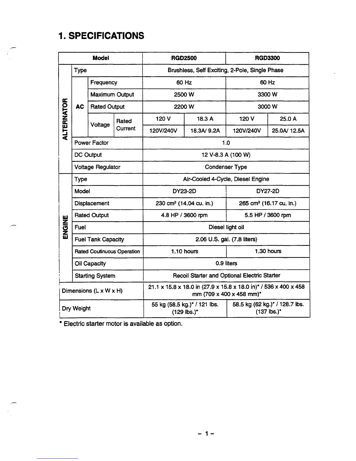
Model
RGD2500
RGD3300
I
Brushless, Self Exciting, 2-Pole, Single Phase
I
I
Frequency 60
Hz
60
Hz
I
Maximum Output
Rated Output
AC
3300
W
2500 W
3000
W
2200
W
Rated
Current
25.0N 12.5A 120Vl240V 18.3N
9.2A
120V/240V
120
v
25.0
A
120
v
18.3
A
Voltage
Power Factor
1
.o
DC Output
Voltage Regulator
12V-8.3
A
(1
00
W)
Condenser Type
Type Air-Cooled CCycle, Diesel Engine
Model DY23-2D
I
i
i
DY27-2D
~
Displacement
I
230 cm3(14.04cu.in.)
I
265
cm3(16.17cu.in.)
I
Rated
Output
4.8
HP
/
3600 rpm
2.06
U.S.
gal. (7.8 liters)
Fuel Tank Capacity
Diesel light oil Fuel
5.5
HP
/
3600
rpm
I
~ ~~ ~~~ ~
Rated
Coutinuous
Operation
I
1.10
hours
I
1.30hours
Oil Capacity
Recoil Starter and Optional Electric Starter
Starting System
0.9
liters
I
Dimensions
(L
x
W
x
H) 21.1
~15.8~18.0in(27.9~15.8~18.0in)’/536~400~458
mm (709
x
400
x.458 mm)*
I
Dry Weight
!
I
55
kg(58.5kg.)’
/
121
Ibs.
58.5 kg (62 kg.)’
/
128.7
Ibs.
I
(129
Ibs.)’
(1
37
I&.)*
Electric
starter motor
is
available as
option.
-
1-

2.
PERFOMANCE
CURVES
2-1
MODEL RGD2500
-
2k
t
A
s
a
n
I-
O
3
-
lk
-0
CURRENT(A)
-
2-2
MODEL
RGD3300
CURRENT
(A)
+
2-3
DC
OUTPUT
16
14
v
5
12
g
10
0246810
CURRENT(A)
"+
3k
2k
t
3
CI
Y
Output
Max.
.................
2500
W
Output Rated
...............
2300
W
Frequency
....................
60
Hz
Voltage
.........................
120
V
Output
Max.
..............
3300
W
Output Rated
............
3000
W
Frequency
.................
60 Hz
Voltage
120
V/240V
e
......................
0
DC
Voltage
..................
12
V
DC
Ampere
.................
8.3
A
DC
output
....................
100
W
The voltage curve shown in the left indicates the char-
acteristic
of
DC
output when charging
a
battery.The
voltage may be decreased
by
20%
when the resis-
tance load
is
applied.
NOTE
:
It
is possible
to
use both
DC
and
AC
outputs
simultaneously up
to
the rated output
in
total.
-
2-

3-1
BRUSHLESSALTERNATOR
Newly developed brushless alternator eliminates troublesome brush maintenance.
3-2
EASYSTARTING
Light pull recoil starter accompanied with automatic decompression system makes the new
RGD
series
generators even easierin starting than gasoline engine generators.
3-3
QUIET
OPERATION
The new
KGD
series generator provides quiet operation by means
of:
The
superb
design
of
intake-exhausr system.
Direct injection combustion system.
A
large super silent muffler.
An efficient
low
noise air cleaner.
3-4
ECONOMICALPERFORMANCE
On
top
of
well
known diesel economy. the air-coolea Robin diesel engine features direct fuel injection
and special designrefinemem for extra fuel efficiency.
3-5
OIL
SENSOR
The
OIL
SENSOR
automatically shuts the engine off whenever the oillevel
falls
down below a safelevel
preventing engine seizure.
3-6
COMPACT, LIGHT WEIGHT
Thecombinationof newiydevelopedbrushless alternatorandair-cooledsinglecylinderRobindiesel
engine enables the new
RGD
series generatorsto be very compact in size and lightin weight.
3-7
RELIABLEPERFORMANCEWITH MINIMAL MAINTENANCE
A
brushless alternator eliminates troublesome brush maintenance.
A
drip-proof alternator design.
A
trouble free condenser voltage regulator.
A
fuselesscircuitbreaker.
A
dust-proof dual element air cleaner.
The
OIL
SESSOR
automatically shuts the engine off whenever the
oil
level falls down below a safe
level preventing engine seizure.
3-8
LONG-LIFEDURABILITY
C'onlpact
and
smooth
running
air-cooledRobindieselenginelastsmuchlongerthanthegasoline
engine
of
the same size.
Trouble-freebrushlessalternatorwithcondensertypevoltageregulatorworksalltheyearround
without any maintenace work.
-
3-

4.GENERAL
DESCRIPTION
4-1
EXTERNAL
VIEW
No-fuse
bmakei
Speed
controlleverRockercover
Fullmwerswitch
I-
/
/
Air cleaner
(DU~
voltage
type
o
Key
switch
(Only
for RGD3300)
\
/
Fuel injection pump
\
DC
output
terminal
Stop
lever
.
Earth
terminal Fuelfi&rOil
filter
Fuelcock
/
Muffler
Electric starter
(only for
RGDSOO)
/
\
Oil
gauge
-
4-

4-2
CONTROL
PANEL
_-
RGD2500, RGD3300
:
60HZ-l20V, 60H~-120V/240V
TYPE
Full
power
switch
Key switch
(Only
for
RGD3300)
Vottmeter
i,
I((
DC
output
terminal
7
DC
fuse
@
1111
/
No-fuse
breaker
/Ac
receptacle
/
Earth
terminal
-
5-
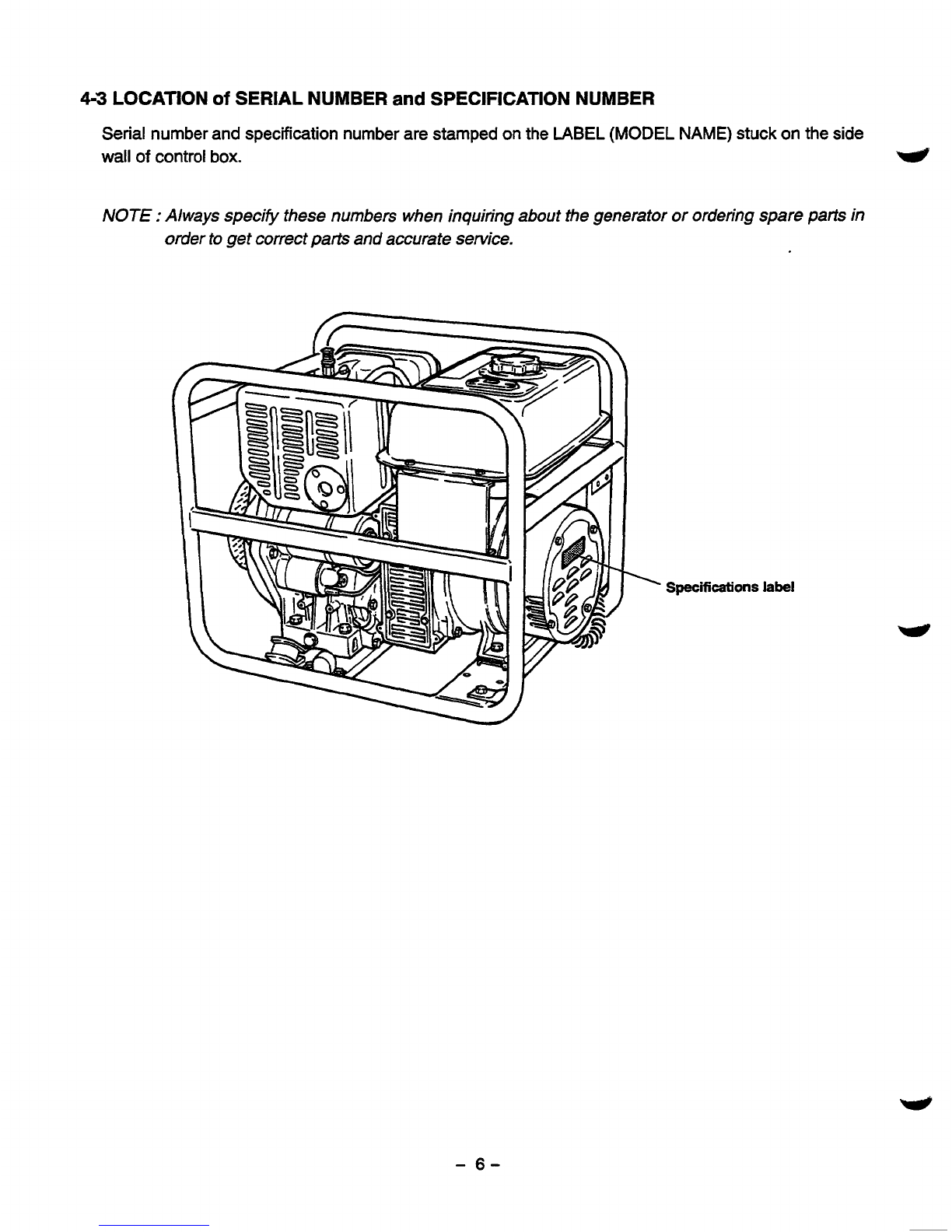
4-3
LOCATION
of
SERIAL NUMBER
and
SPECIFICATION NUMBER
Serial number and specification number are stamped
on
the
LABEL
(MODEL
NAME)
stuck on the side
wall
of
control
box.
w
NOTE
:
Always specify these numbers when inquiring about the generator or orderingspare
parfs
in
order to get correct
parts
and accurate service.
Specifications
label
-
6-
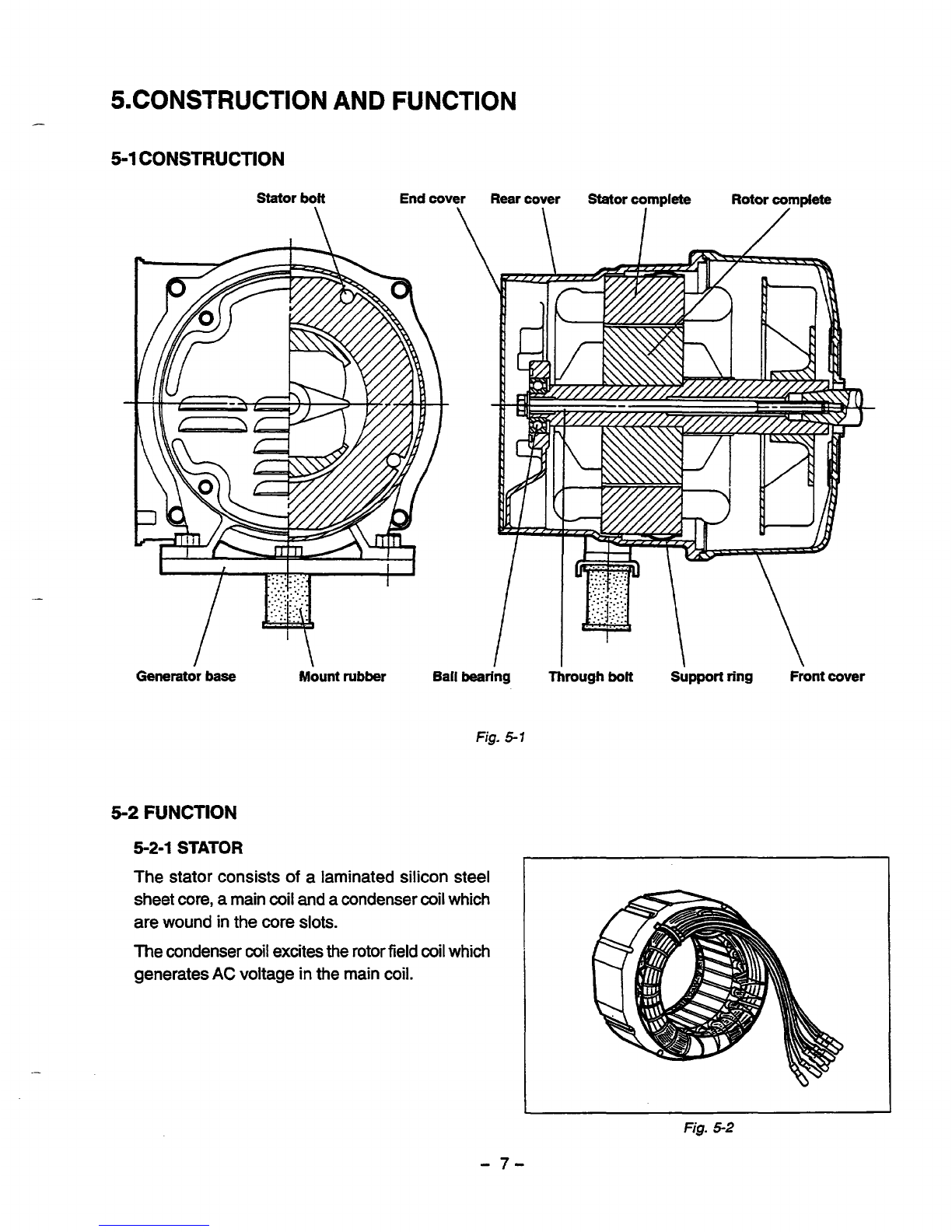
5.CONSTRUCTION
AND
FUNCTION
GeneratorbaseMountrubber BallbearingThrough
bolt
Support
ring
Frontcover
Fig-
5-7
5-2
FUNCTION
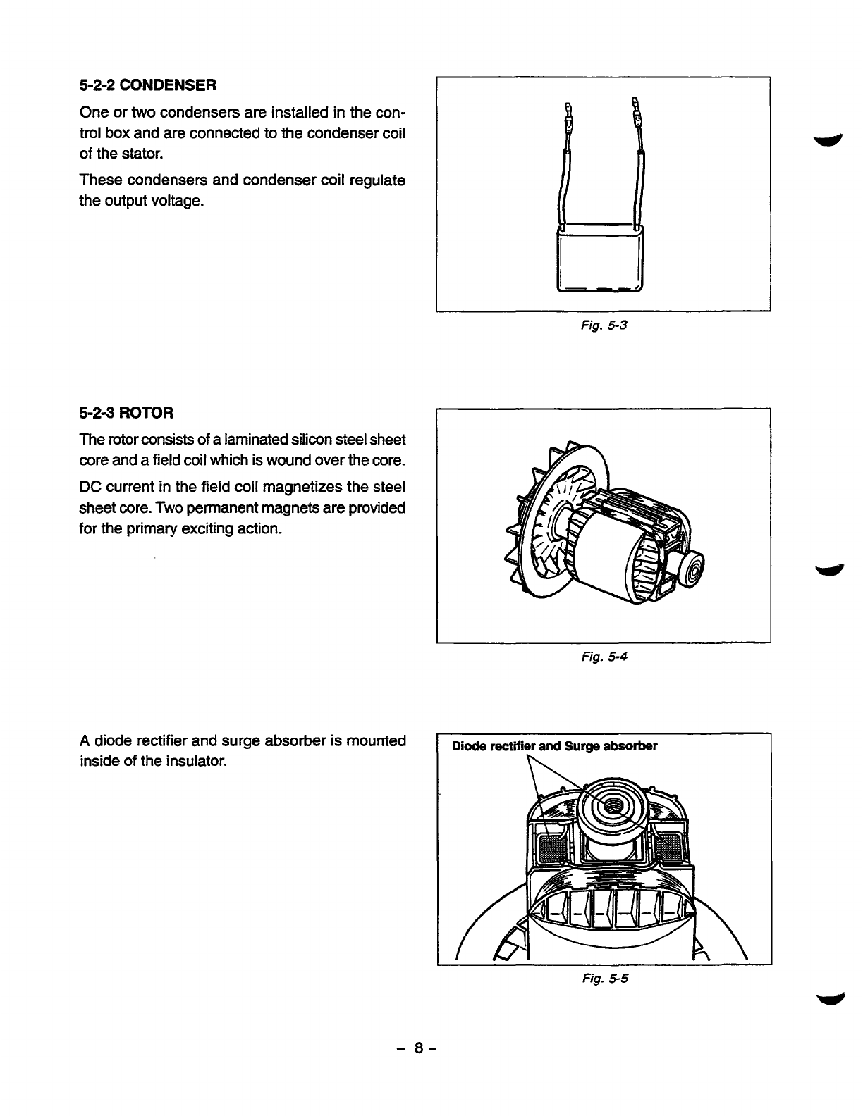
5-2-1
STATOR
The stator consists
of
a
laminated silicon steel
sheet
core,
a
main
coil
and
acondenser coil which
are woundinthe core
slots.
The condenser coil excites the rotor field
coil
which
generates
AC
voltage inthe main
coil.
Fig.
5-2
-
7-
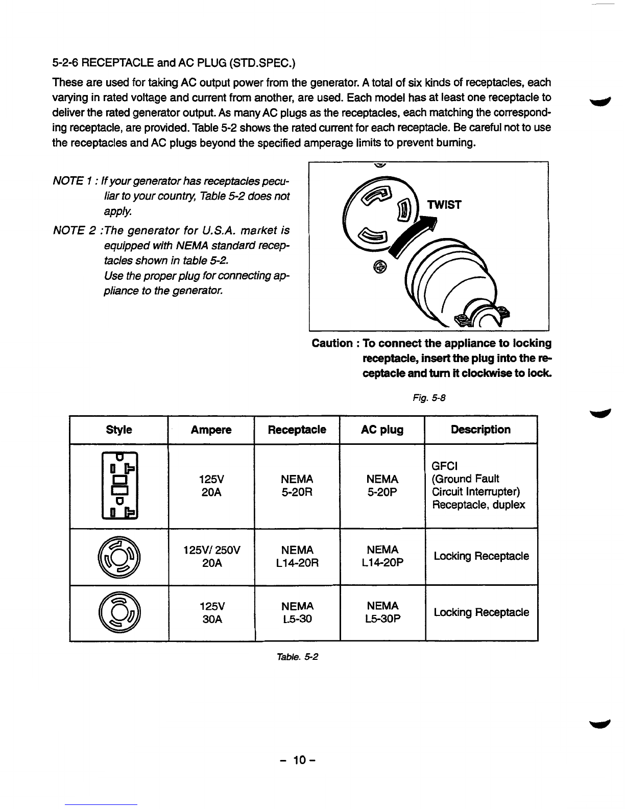
5-2-2
CONDENSER
One or
two
condensers are
installed
in
the
con-
trol
box
and are connected
to
the condenser coil
of
the stator.
These condensers and condenser coil regulate
the
output
voltage.
5-24
ROTOR
The rotor consists
of
a laminated silicon steel sheet
core andafield coil which
is
wound over the core.
DC
current
in
the field coil magnetizes
the
steel
sheet
core.Two permanent magnetsare
provided
for
the primary exciting action.
A
diode rectifier and surge absorber
is
mounted
inside
of
the
insulator.
I
Fig.
53
Fig.
5-4
Diode
rectifier and
Surge
absorber
Fig.
5-5
-
a-

5-2-4
DC
FUSE
(1)
The
10
ampere DC fuse mountedon the con-
trol panel protects whole DC circuit from get-
ting damage by overload or short circuit.
(2)
The
15
ampere DC fuse
in
the control box pro-
tects the diode rectifier from getting damage
by reverse connectionto thebattery.
(Electric
start
model)
I
Fig.
5-6
5-2-5
NO-FUSE
BREAKER
The no-fuse breaker protects the generator from getting damage by overloading or short circuit
in
the
appliance.Table
5-1
shows
thecapacrty of no-fuse breaker by each spec.
and
their object of protection.
MODEL OBJECT
or
PROTECTION
NO-FUSE
BREAKER
SPECIFICATION
60
HZ-120
V
RGD2500 20
A
10Ax2
60
HZ-1
20
V,
240V
Total output amperage
Total
output
amperage
RGD3300 60 HZ-120
V
Total output amperage
14Ax2
60
HZ-1 20 V, 240V
Total output amperage
27
A
Table.
5-1
1
Fig.
5-7
-
9-
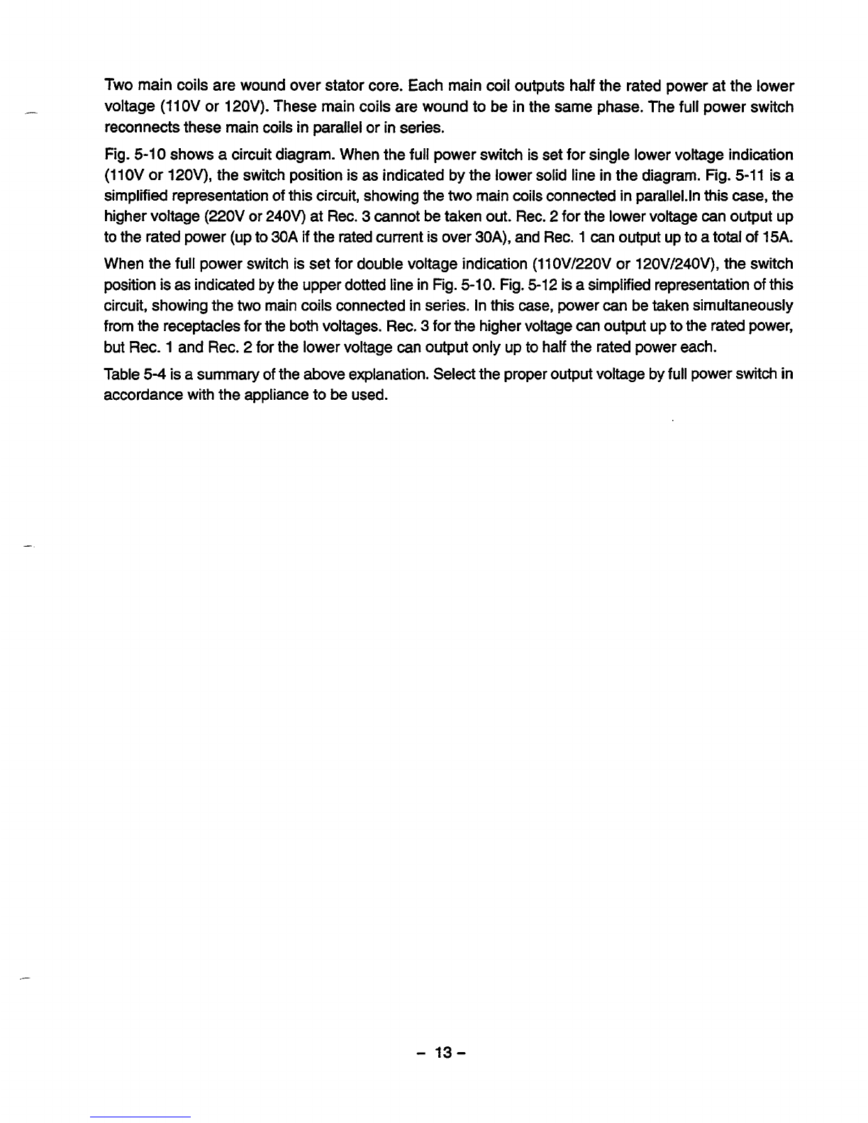
5-2-6 RECEPTACLE
and
AC PLUG
(STD.SPEC.)
These are used for taking AC output power from the generator.
A
total
of
six kinds
of
receptacles, each
varying inrated voltage and current from another, are used. Each model has at least one receptacle to
deliver the rated generator output.
As
many AC plugs
as
the receptacles, each matching the correspond-
ing receptacle, are provided. Table
5-2
shows the rated current for each receptacle. Be careful not to use
the receptacles and AC plugs beyond the specified amperage limitsto prevent burning.
w
NOTE
7
:
If
your generator has receptacles pecu-
liar
to
your
county,
Table
5-2
does not
apply.
NOTE
2
:The generator for
U.S.A.
market is
equipped withNEMA standard recep-
tacles shown
in
table
5-2.
Use the proper plug for connecting ap-
pliance to the generator.
Caution
:
To
connect the appliance
to
locking
receptacle, insert
the
plug intothe
re-
ceptacle and
turn
it
clockwise to
lock.
Fig.
5-8
Style
Description
AC plug
Receptacle
Ampere
~1
20A
GFCl
125V
(Ground Fault
NEMA NEMA
5-20R
Circuit interrupter)
5-20P
Receptacle, duplex
@
125VI250V NEMA NEMA
20A
L14-2OP L14-20R
Locking Receptacle
1
25V
L5-30P
L5-30
30A NEMA
NEMA
Locking Receptacle
Table.
5-2
-
10-

5-3
GENERATOR OPERATION
PERMANENT MAGNET
FOR
INITIAL EXCITATION
FIELD
COIL
\
STATOR
r---
1
MAIN
COIL
I
"""1
I
"""""I
Fig.
5-9
5-3-1
GENERATION
Of
NO-LOAD VOLTAGE
(1)
When the generator starts running,
the
permanent magnet built-intothe rotor generates
3
to
6V
of AC
voltage inthe main coil and condenser coil wound on the stator.
(2)
As
one or
two
condensers are connected to the condensercoil, the small voltage at the condenser
coilgenerates a minute current
8)
which flows through the condenser coil.
At
this time,
a
small fluxis
produced with which the magnetic force at the rotor's magnetic pole is intensified.When this mag-
netic forceis intensified, the respective voltages in the main coil and condenser coil rise up.
As
the
current
3
increases, the magnetic flux at the rotor's magnetic pole increases further. Thus the volt-
ages at the main coil and condenser coil keep rising
by
repeating this process.
(3)
As
AC
current flows through the condenser coil, the density of magnetic fluxinthe rotor changes. This
change of magnetic flux induces
AC
voltage in the field coil, and the diode rectifierinthe field coil
circuit rectifies this
AC
voltage into DC. Thus a DC current
13
flows through the field coil and magne-
tizes the rotor core to generate an output voltage in the main coil.
(4)
When generator speed reaches
3000
to
3300
rpm, the currentinthe condenser coil and field coil
increases rapidly. This acts to stabilize the output voltage
of
each coils.
If
generator speed further
increasestothe rated value, the generator output voltage
will
reach to the rated value.
5-3-2
VOLTAGE FLUCTUATIONS UNDER LOAD
When the
output
current
@
flows through the main coil to the appliance, a magnetic fluxisproduced and
serves to increase current
@
in the condenser coil. When current
@
increases, the density
of
magnetic
flux across
the
rotor core rises.
As
a result, the current flowing in the field coil increases and the genera-
tor output voltage is prevented from decreasing.
-
11
-

5-3-3 FULL
POWER
SWITCH
(Dual
Voltage
Type)
The full power switch
is
provided forthe dual voltage typetotake
out
the full rated power from one
receptacle ineach voltage.
1"
REc21&
$""
/
-
-
I
,
IREC1
Fig. 5-
11
-1
1
OV)
1 1
RECEPTACLE
I
RECEPTACLE
LOWER
VOLTAGE
HIGHER
VOLTAGE
110
v
I
,orv
I
Rated
output
I
No
output
can
be
taken.
I
110/220
v
120/240
V
or
Tale.
5-4
Rated output
Half
of
rated
output
Fig. 5-12
-
12-
Two main coils are wound over stator core. Each main coil outputs
half
the rated power at the lower
voltage
(11OV
or
12OV).
These main coils are wound to beinthe same phase. Thefull power switch
reconnects these main coils
in
parallel or
in
series.
Fig.
5-1
0
shows
a
circuit diagram. Whenthe fullpower switchisset for single lower voltage indication
(11OV
or
12OV),
the switch positionisas indicated by the lower solid line in the diagram.Fig.
5-11
is
a
simplified representation of this circuit, showing the
two
main coils connected
in
parallel.ln this case, the
higher voltage
(22OV
or
240v)
at Rec.
3
cannot be taken out. Rec.
2
for the lower voltage can output up
to the rated power (up to
30A
if
the rated current
is
over
30A),
and Rec.
1
can
output
up to
a
totalof
15A.
When the fullpower switchisset for double voltage indication
(11OV/22OV
or
120V/240V),
the switch
positionisas indicated by the upper dotted line in Fig.
5-10.
Fig.
5-12
is a simplified representation
of
this
circuit, showing the
two
main coils connectedinseries. In thiscase, power
can
be taken simultaneously
fromthereceptacles for the both voltages. Rec.
3
for the higher voltage can output uptothe rated power,
but Rec.
1
and Rec.
2
for the lower voltage can output only up to half the rated power each.
Table
5-4
is
a
summary
of
the above explanation. Select the proper output voltage by full power switch
in
accordance withtheappliance to beused.
"
-
13-

6.:
SAFETY
PRECAUTIONS
1.
Useextreme caution near fuel. A constantdanger
of
explosion or fireexists.
Do
not fill the fuel tank whilethe engineis running.
Do
not smoke or use opem flame nearthe fuel
tank. Be careful not to spill fuel when refueling.
If
spilt, wipeitand let dry before starting the engine.
2. Do
not place inflammablematerialsnear the generator.
Be careful notto put fuel, matches, gunpowder, oily cloth, straw, and any other inflammables near the
generator.
3.
Do
notoperatethe generator inaroom,cave ortunnel. Always operatein
a
well-ventilatedarea.
Otherwise the engine may overheat and also, the poisonous carbon monoxide contained in the ex-
haust gases will endanger human lives. Keep the generator at least
1
m
(4
feet) away from structures
or facilities duringuse.
4.Operate the generator ona levelsurface.
5.
6.
If
the generator
is
tilted or moved during use, thereisa danger
of
fuel spillage and a chance that the
generator may tip over.
Do
notoperatewith wet handsor
in
the rain.
Severe electric shock may occur.
If
the generatoriswet by rain or snow, wipe
it
and thoroughly
dry
it
before starting.
Don't
pour water overthegenerator directly nor washitwith water. If the generatoris
wet with water, the insulations
will
be adversely affected and may cause current leakage and electric
shock.
Do
notconnectthe generatortothecommercial power
lines.
w
This may cause a short-circuit or damagetothe generator. Use a transfer switch (Optional parts) for
connecting with indoor wiring.
NOTE
:
Theparts numbers
of
the transfer swifches and
of
the
plastic box to store themareas
shown
in
Table
6-
1.
Part
No.
PartName
Q'ty
Phase
Allowable
Current
Table.
6-1
365-45604-08 Transfer
Switch
11 15
A
367-45605-08 Transfer
Switch
11 30
A
340-45606-08
Transfer Switch
1
1
60
A
367-43008-08
Plastic
Box
11
30
A
348-43009-08
Plastic
Box
1160
A
Table.
6-1
7.
Be sureto check andremedy thecauseof circuitbreaker tripping
before
resetting
it
on.
CAUTION
:
If
the circuitbreakertripped
off
asa resultof using anelectricalappliance,the cause
can
be
an overload or a short-circuit.
In
sucha case, stop operationimmediatelyand carefully
check theelectricalapplianceandAC
plugs
for faulty wiring.
-
14-
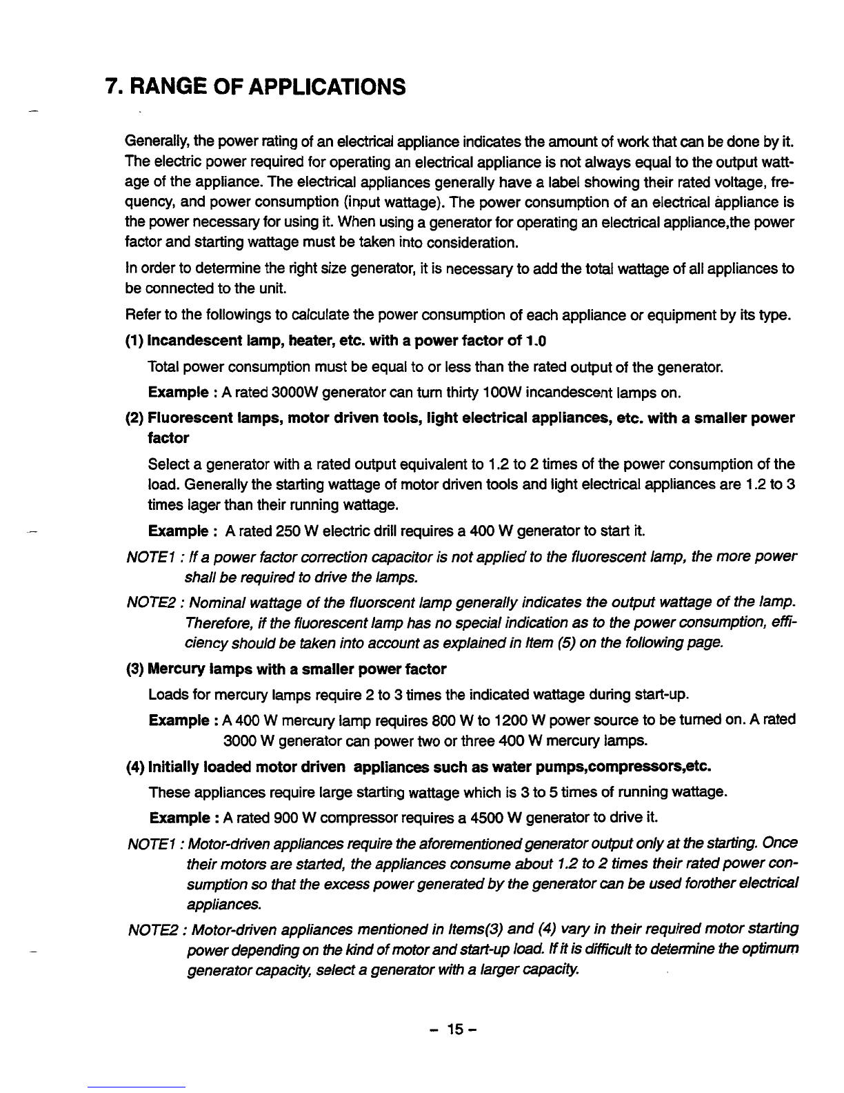
Generally, the power rating of an electrical appliance indicates the amount of work that can be done by
it.
The electric power required for operating an electrical applianceis not always equal to the output watt-
age of the appliance. The electrical appliances generally have a label showing their rated voltage, fre-
quency, and power consumption (input wattage). The power consumption
of
an electrical appliance is
the power necessary for using it. When using a generatorfor operating an electrical appliance,the power
factor and starting wattage must be taken into consideration.
Inorder to determine the right size generator,itis necessary to add the
total
wattage of all appliancesto
be connectedtothe unit.
Refer
to the followings to calculate the power consumption of each appliance or equipment by its type.
(1)
Incandescent lamp, heater, etc. witha power factor of
1
.O
Total power consumption must be equal to or less than the rated output of the generator.
Example
:
A
rated 3000W generator can turn thirty
lOOW
incandescent lamps on.
(2)
Fluorescent lamps, motor driven tools, light electrical appliances, etc. witha smaller power
factor
Select a generator with a rated output equivalent to
1.2
to
2
times of the power consumption of the
load. Generally the starting wattage of motor driven tools and light electrical appliances are
1.2
to 3
times lager than their running wattage.
Example
:
A
rated
250
W electric drill requires a
400
W
generator to start
it.
NOTE
7
:
If a power factor correction capacitor is not applied to the fluorescent lamp, the more power
shall be required to drive the lamps.
NOTE2
:
Nominal wattage of the fluorscent lamp generally indicates the output wattageof the lamp.
Therefore,
if
the fluorescent lamp has no special indication as to the power consumption,efi-
ciency should be taken into account as explainedinitem
(5)
on the following page.
(3)
Mercury lamps witha smaller power factor
Loads for mercury lamps require
2
to 3 times the indicated wattage during start-up.
Example
:
A
400
W mercury lamp requires
800
W to
1200
W power source to be turned on.
A
rated
3000
W
generator can power
two
or three
400
W
mercury
lamps.
(4)
Initially loaded motor driven appliances suchas water pumps,compressors,etc.
These appliances require large starting wattage whichis3 to
5
times
of
running wattage.
Example
:
A
rated
900
W compressor requires a
4500
W
generator to drive it.
NOTE
7
:
Motor-driven appliances require the aforementioned generator output onlyattheshdng. Once
their motors are started, the appliances consume about
7.2
to
2
times their rated power con-
sumption
so
that the excess power generated by the generator can
be
used forother electrical
appliances.
NOTE2
:
Motor-driven appliances mentioned in Items(3) and
(4)
vary
in their required motorsbrting
power depending on the kind of motor and start-up load.
if
it
is
dficulttodetermine the
optimum
generator capacw, select a generator with a larger capaciw.
-
15-
(5)Appliances without
any
indication as to power consumption
Some appliances have no indication asto power consumption; but instead the work load (output)is
indicated. In such a case, power consumptionisto beworked out accordingto the numerical formula
mentioned below. (Output
of
electrical appliance)
(Efficiency)
=
(Power consumpition)
Efficiencies of some electrical appliances are as follows
:
Single-phase motor
................................
Fluorescentlamp
...................................
0.7
to
0.8
lowertheefficiency.
Oe6
to
0-753(
The smaller the motor, the
Example
1:
A
40W
fluorescent lamp means that its luminous output
is
40W.
Its efficiencyis0.7 and
accordingly, power consumptionwill be
40
t
0.7=
57W.
As
explained in Item (2), multiply
this power consumption value of57
W
by
1.2
to
2
and you
will
get the figure of the neces-
sary
capacity
of
a generator.
In
other words, a generator with a rated output
of
1OOOWcapacity
can
light nine to fourteen
40
W fluorescent lamps.
Example
2
:
Generally speaking, a
400
W
motor means that its work loadis
400
W.
Efficiency
of
this
motor is
0.7
and power consumption will be
400+0.7=
570
W.
When this motoris used for
a motor-driven tool, the capacity of the generator should
be
multiple of 570
W
by 1.2to
3
as
explained in the Item
(3).
570
(W)
x
1.2
to
3
=
684
(W)
to 1710
(W)
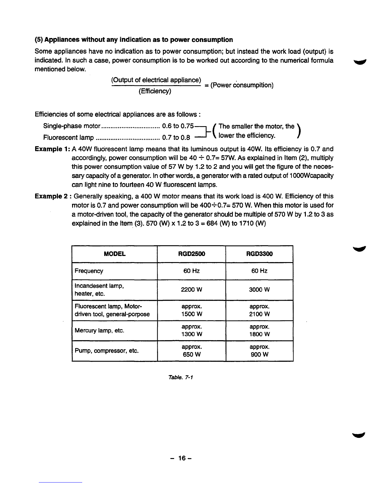
MODEL RGD3300 RGD2500
Frequency
I I I
60
Hz
60
Hz
lncandesent
lamp,
heater, etc.
I
22OOw
I
30OOW
Fluorescent lamp, Motor-
2100
w
15OOW
driven
tool,
general-porpose approx.
approx.
~~~~~
Mercury
lamp,
etc.
approx. approx.
1
13OOW
I
18WW
Pump, compressor, etc. approx.
approx.
1
650
W
Table.
7-1
-
16-
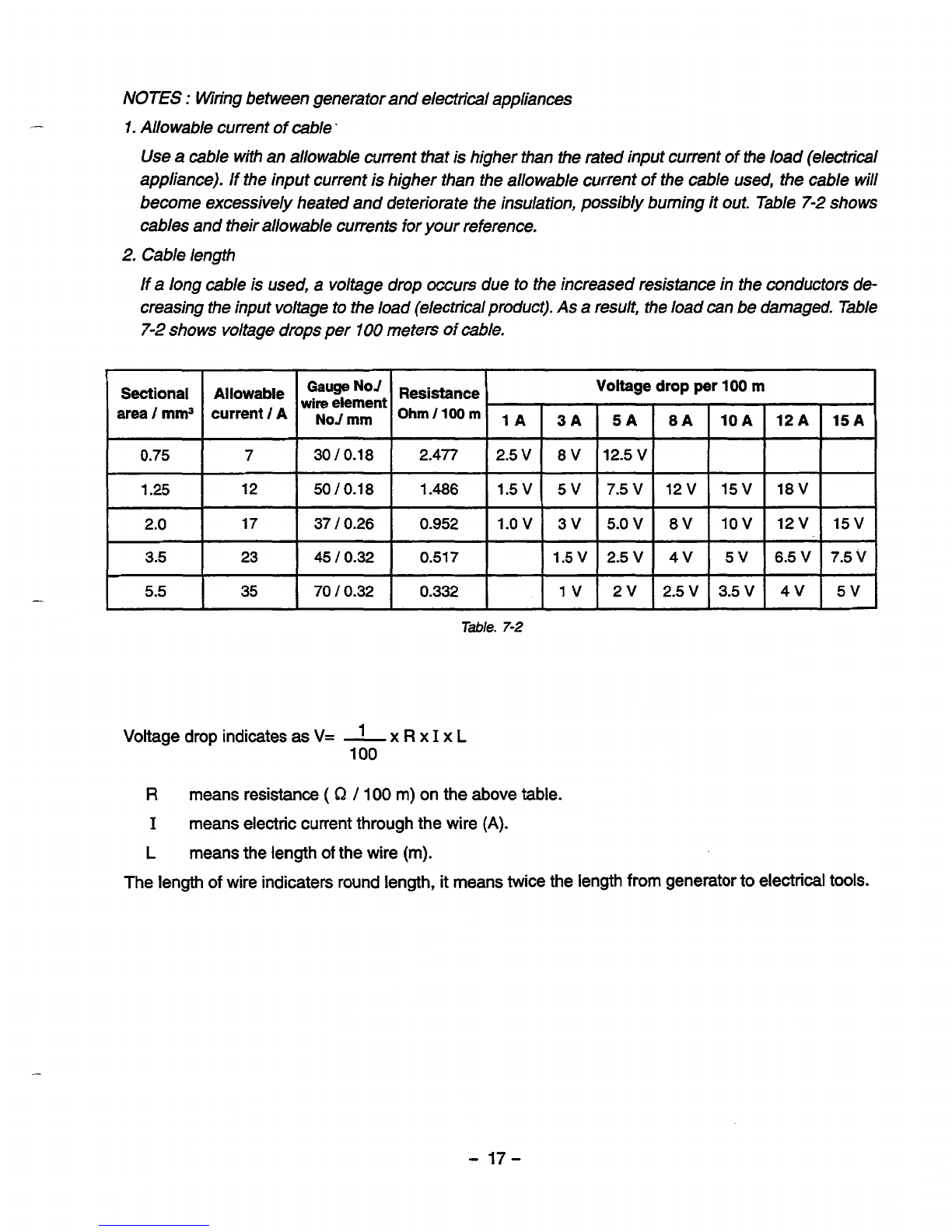
NOTES
:
Wringbetween generator and electrical appliances
I.
Allowable current ofcable.
Use a cable with an allowable current that is higher than the rated input current of the load (electrical
appliance). If the input current is higher than the allowable current
of
the cable used, the cable will
become excessively heated and deteriorate the insulation, possibly burning it out. Table
7-2
shows
cables and their allowable currents for your reference.
2.
Cable length
If a long cable is used, a voltage drop
occurs
due to the increased resistance in the conductors de-
creasing the input voltage to the load (electrical product). As a result, the load
can
be damaged.Tabe
7-2
shows voltage drops per
I00
meters
of
cable.
"
"
Sectional
area
/
mm3
0.75
1.25
2.0
3.5
5.5
Gauge
No'
wire
dement
Resistance
Voltage
A"owab'e
current
/
A
mm
Ohm/100m
1~
3~
5~
7
I
3010.18
I
2.477
I
2.5
V
I
8
V
112.5
V
12
50
10.18
1.486
1.5V 5V 7.5V
17
3710.26
0.952
1.0
V
3V 5.0
V
23
I
45/0.32
I
0.517
I
I
1.5V
I
2.5
V
Table.
7-2
Voltage drop indicatesas
V=
-
x
R
x
I
x
L
1
100
drop
per
100
m
4V
I
5V
16.5V
2.5v
I
35-v
I
4
v
7.5
v
I
5v
I
R
meansresistance
(
hz
/
100
m)on the abovetable.
I
meanselectriccurrentthroughthewire
(A).
L
meansthelength
of
thewire
(m).
The length
of
wire indicaters round length, it means twice the length from generator to electrical tools.
-
17-
This manual suits for next models
1
Table of contents
Other Robin Inverter manuals


Popular Inverter manuals by other brands


EG4
EG4 3000 EHV-48 user manual

Midian Electronics
Midian Electronics MOT-TVS-2-PRO instructions

Gondzik
Gondzik NL-BKDX30-95II/R user manual

SEW-Eurodrive
SEW-Eurodrive MOVIDRIVE modular Compact operating instructions

SolarEdge
SolarEdge BI-EU1P Quick installation guide

Generac Power Systems
Generac Power Systems 2.4L owner's manual


