2’’-6’’ SHOCK ABSORBERS – MAINTENANCE AND SERVICE MANUAL
3
2. Servicing & Maintenance
The Robit HD range of Shock Absorbers, suitable for 2” through to 6” DTH hammers should be serviced
after every 500 hours of operation or every 6 months of intermittent use.
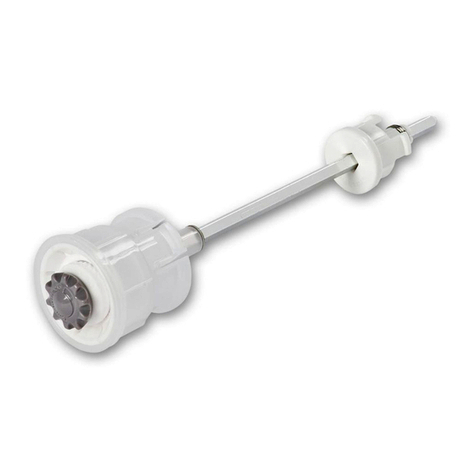
To disassemble the unit the Top Connector (item 1) needs to be unscrewed from the Bottom Connector
(item 10). This can best be achieved by locking the Bottom Connector either in a vice or hammer
splitting bench, depending on the size of the Shock Absorber and splitting the Top Connector at the
spanner ats on the Splined Nut (item 3).
If the Shock Absorber is proving particularly dicult to break open, then by cutting through the
Breakout Washer (item 4) with a pencil grinder or similar, this should facilitate easier opening. Take care
not to cut into the Locking Nut. Note the 2” HDSA2 does not feature a breakout washer.
Remove and carefully inspect the Buers (item 9). If either of them is showing any signs of wear,
distortion or fatigue they must both be replaced.
Remove the Retainer Ring (item 6) and Slide the Splined Nut o the Top Connector. Examine the Seal
“O” Ring (item 2) and also the Seal and if they are showing any signs of wear or distortion, they must be
replaced.
It is inevitable that there will be progressive wear between splines of the Top Connector shaft
and those of the Splined Nut. When this wear pattern exceeds 2mm in either component, it is
recommended that this component be replaced. Excessive wear will eventually lead to failure of the
Top Connector shaft or thread with the consequent loss of both hammer and bit.
Before re-assembling the Shock Absorber, make sure all the components are cleaned and then apply a
good quality, heat resistant grease to the splines of the Top Connector shaft and the splines of the Nut.
This will both reduce wear and help in splitting when the unit is next ready for service.
With the Top Connector held in the vertical position, slide over the Splined Nut and attach the Retainer
Rings to the Top Connector. Ensure that the Thrust Guide and Buers are all in line then place the
Bottom Connector over the Splined Nut and tighten down fully to a maximum torque value as shown
below for the appropriate Shock Absorber size.
Maximum Torque Values
2 ‘‘ HDSA2 170 kgm
3 ‘‘ HDSA3 200 kgm
4 ‘‘ HDSA4 250 kgm
5 ‘‘ HDSA5 400 kgm
6 ‘‘ HDSA6 700 kgm
