Robitronic Razer ten ESC // COMBO User manual

1
Bedienungsanleitung / Manual
RAZER ten ESC // COMBO
Art.Nr.: R01221 / R01222 // R01250 / R01251 / R01252 / R01253
Einleitung
Herzlichen Glückwunsch und vielen Dank für Ihr Vertrauen in Robitronic. Durch die Wahl des RAZER ten ESC
Brushless Reglers, haben Sie sich für einen Hochleistungsregler mit Hightech-Funktionen entschieden!
Bitte lesen Sie diese Anleitung vor der ersten Inbetriebnahme sorgfältig durch. Somit vermeiden Sie unsach-
gemäßen Gebrauch. Nicht autorisierte Änderungen an unserem Produkt sind ausdrücklich verboten da diese
gefährlich sind und das Gerät beschädigen könnten. Wir behalten uns das Recht vor, das Design, technische Daten
und Benutzungsanforderungen ohne Benachrichtigung zu ändern.
Eigenschaften
•Vollständig wasserdicht. (Anm.: Entfernen Sie den Lüfter bei Betrieb mit Wasserkontakt, bitte säubern und
trocknen nach Gebrauch, um rostige Kontakte zu vermeiden)
•Ein Zuverlässiger Schalter verhindert Ausfälle durch Schmutz, Wasser, Staub usw.
•Eingebautes S-BEC mit 6V und 3A Spitzenstrom.
•Einstellbare Bremsfunktion und Handbremsfunktion für verschiedene Fahrzeuge, Strecken und Untergründe.
•4 verschiedene Beschleunigungseinstellung von weich bis aggressiv für verschiedene Fahrzeuge, Reifen und
Untergründe.
•Mehrfache Schutzvorrichtungen: Unterspannungsabschaltung, thermischer Schutz und Schutz bei Signalverlust.
•Einfache Regler-Programmierung und werkseitige Rücksetzung.
•Separater Programmier-Port zum einfachen Verbinden der LED-Programmkarte mit dem Regler.
Warnhinweise
•Zur Vermeidung von Kurzschlüssen ist darauf zu achten, dass alle Drähte und Anschlüsse gut isoliert sind, bevor
Sie den Regler anschließen.
•Vergewissern Sie sich, dass alle Komponenten ordnungsgemäß angeschlossen sind um Schäden an den
elektrischen Komponenten zu vermeiden.
•Lesen Sie die Bedienungsanleitung aller stromführenden Komponenten sorgfältig durch und stellen Sie sicher,
dass die Konfiguration der Komponenten auf einander angestimmt ist.
•Verwenden Sie zum Löten aller Ein- / Ausgangsleitungen und Anschlüsse einen Lötkolben mit einer Leistung von
mindestens 60 Watt.
•Halten Sie das Fahrzeug nicht in der Luft und geben Vollgas. Die Gummi-Reifen vergrößern sich durch den
fehlenden Widerstand extrem und können unter Umständen platzen, was schwere Verletzungen verursachen
kann.
•Den Gebrauch und Betrieb stoppen, sobald das Gehäuse des Reglers 90 °C übersteigt, da dies sowohl den
Regler als auch den Motor beschädigen kann. Ab Werk ist der Überhitzungsschutz auf 105 ℃eingestellt (dies
entspricht der internen Temperatur des Reglers).
•Trennen Sie nach Gebrauch immer den Akku vom Regler. Der permanente Anschluss eines Akkus am Regler
über einen längeren Zeitraum kann zur Beschädigung und/oder Tiefentladung des Akkus oder Reglers führen.
Dies wird NICHT durch die Garantie abgedeckt.

2
Technische Daten
RAZER ten 50A
R01221 // R01250
Konstant-/Spitzenstrom
50A / 300A
Motortyp
Sensorlose Motoren
Anwendung
1/10 Onroad und Offroad
Motorlimit
2S Onroad: 3650er Motor, ≥8T; 2S Offroad: 3650er Motor, ≥11T
3S Onroad: 3650er Motor, ≥11T; 3S Offroad: 3650er Motor, ≥14T
Innenwiderstand
0,0010Ohm
LiPo / NiMH Akkupack
2-3S LiPo / 6-9 Zellen NiMH
S-BEC Ausgang
6V, 3A (Der eingebaute Lüfter läuft über internes BEC immer mit 6V)
Programmier-Port
Lüfter-/Programmieranschluss am Regler
Abmessungen
48,5 x 38x 32 mm
Gewicht
90g
RAZER ten 60A
R01222 // R01251 / R01252 / R01253
Konstant-/Spitzenstrom
60A / 390A
Motortyp
Sensorlose Motoren
Anwendung
1/10 Onroad und Offroad
Motorlimit
2S Onroad: 3650er Motor, ≥5,5T; 2S Offroad: 3650er Motor, ≥8,5T
3S Onroad: 3650er Motor, ≥9T; 3S Offroad: 3650er Motor, ≥13T
Innenwiderstand
0,0012Ohm
LiPo / NiMH Akkupack
2-3S LiPo / 6-9 Zellen NiMH
S-BEC Ausgang
6V, 3A (Der eingebaute Lüfter läuft über internes BEC immer mit 6V)
Programmier-Port
Lüfter-/Programmieranschluss am Regler
Abmessungen
48,5 x 38 x 32 mm
Gewicht
90g
Verkabelung
Achtung: Dies ist ein extrem leistungsfähiges Brushless-Motor-System. Zu Ihrer Sicherheit und der Sicherheit der
Personen um Sie herum, wird dringend empfohlen das Ritzel am Motor zu entfernen, bevor Sie mit der
Programmierung und Kalibrierung beginnen. Ebenso ist es ratsam bei Inbetriebnahme die Räder in der Luft zu
lassen, also ohne Bodenkontakt, wenn Sie den Regler einschalten.

3
•Motorverdrahtung:
Es gibt keine Polarität der Motor-Drähte, daher können Sie diese sie zunächst verbinden. Eventuell müssen Sie
zwei der drei Drähte umtauschen, wenn der Motor verkehrt läuft.
•Empfängeranschluss:
Stecken Sie das Gaskanal-Kabel am Regler in den TH-/Gaskanal am Empfänger. Das Gaskanal-Kabel gibt die
Spannung von 6V an den Empfänger und das Lenkservo aus. Achten Sie darauf keinen separaten Akku an den
Empfänger anzuschließen, ansonsten kann Ihr ESC beschädigt werden.
•Akkuanschluss:
Richtige Polarität ist extrem wichtig. Bitte stellen Sie sicher, dass der Pluspol (+) an Plus (+) und der Minuspol (-)
an Minus (-) des Akkus angeschlossen ist. Wenn umgekehrte Polarität an Ihrem Regler vom Akku anliegt, wird
Ihr Regler beschädigt, was NICHT über die Garantie abgedeckt wird!
Regler Kalibrierung
Beginnen Sie mit der Kalibrierung des Reglers mit dem Sender.
1. Stellen Sie sicher, dass alle Parameter (D/R, Kurve, ATL) und die "ABS Bremsfunktion" am Gaskanal auf Default
sind (entsprechend 0 oder 100%). Für Sender ohne LCD-Display, drehen Sie den Drehknopf bis zum Maximum,
und "TRIM" auf 0. Bitte stellen Sie den entsprechenden Drehknopf auf neutrale Position. Für Futaba-Sender
muss die Richtung des Gaskanals auf "REV" eingestellt werden, während andere Sender nicht geändert werden
müssen bzw. auf "NOR" stehen.
2. Nur den Sender einschalten. Der Regler bleibt ausgeschalten ist aber an einen Fahrakku angeschlossen. Halten
Sie nun die SET Taste gedrückt und schalten Sie gleichzeitig den ESC ein.
Die rote LED auf dem Regler beginnt zu blinken (Hinweis: der Motor piept gleichzeitig) und dann die Taste SET
sofort wieder loslassen. Wenn die Taste nicht binnen 3 Sek. losgelassen wird wechselt der Regler in den
Programmiermodus, falls dies nicht gewünscht wird, bitte neu starten ab Schritt 1.).
Hinweis: Signaltöne vom Motor können manchmal leise sein, aber Sie können stattdessen den LED-Status
überprüfen.
3. Die Neutralstellung, den vollen
Endpunkt der Vollgasposition und den
Endpunkt der Vollbremsung wie folgt
einstellen:
• Lassen Sie den Sender in der
Neutralstellung, betätigen Sie die SET-
Taste, die grüne LED blinkt 1 Mal und
der Motor piept 1-mal um die
Neutralposition zu übernehmen.
• Ziehen Sie den Gashebel auf
Vollgasposition, drücken Sie die SET-
Taste, die grüne LED blinkt 2 Mal und
der Motor wird 2-mal piepsen, um die
Vollgasposition zu übernehmen.
• Schieben Sie den Gashebel auf
Vollbremsposition, drücken Sie SET-
Taste, die grüne LED blinkt dreimal
und der Motor piept dreimal, um die
Vollbremsposition zu übernehmen.
4. Der Motor kann 3 Sekunden nach
Abschluss der Regler-/
Fernsteuerungs-kalibrierung gestartet
werden.
Drücken und halten sie den SET-Taster . Schalten Sie gleichzeitig den Sobald die rote LED blinkt,
Empfänger ein. lassen Sie den SET-Taster los.

4
Erklärung/Prüfen der LED-Statusanzeige:
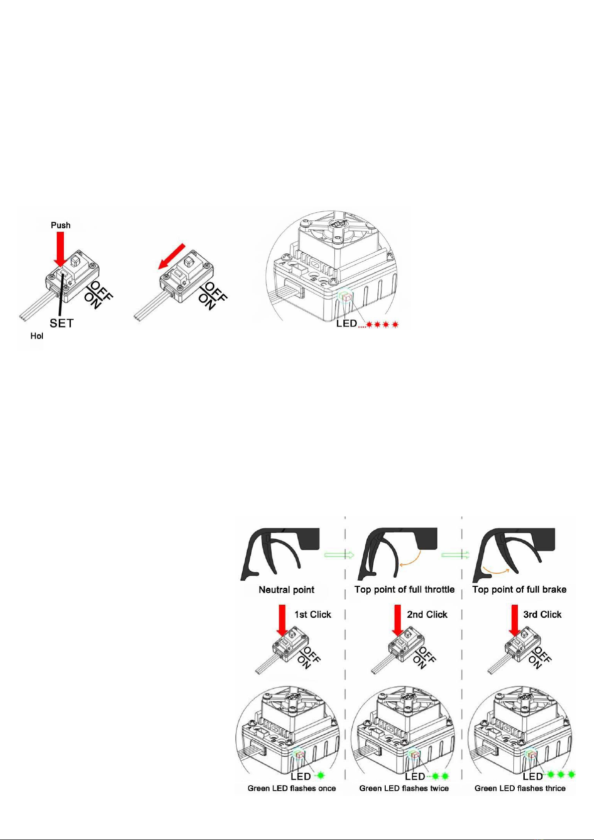
•Wenn sich der Gashebel in der Neutrallage befindet darf keine LED leuchten.
•Die rote LED leuchtet, wenn das Fahrzeug vorwärtsfährt, und es leuchtet zusätzlich die grüne LED, wenn sich der
Gashebel in Vollgasstellung befindet.
•Die rote LED leuchtet, wenn das Fahrzeug bremst, und es leuchtet zusätzlich die grüne LED, wenn sich der
Gashebel auf Vollbremsstellung befindet und die maximale Bremskraft auf 100% einstellt ist.
•Die rote LED leuchtet, wenn das Fahrzeug rückwärtsfährt.
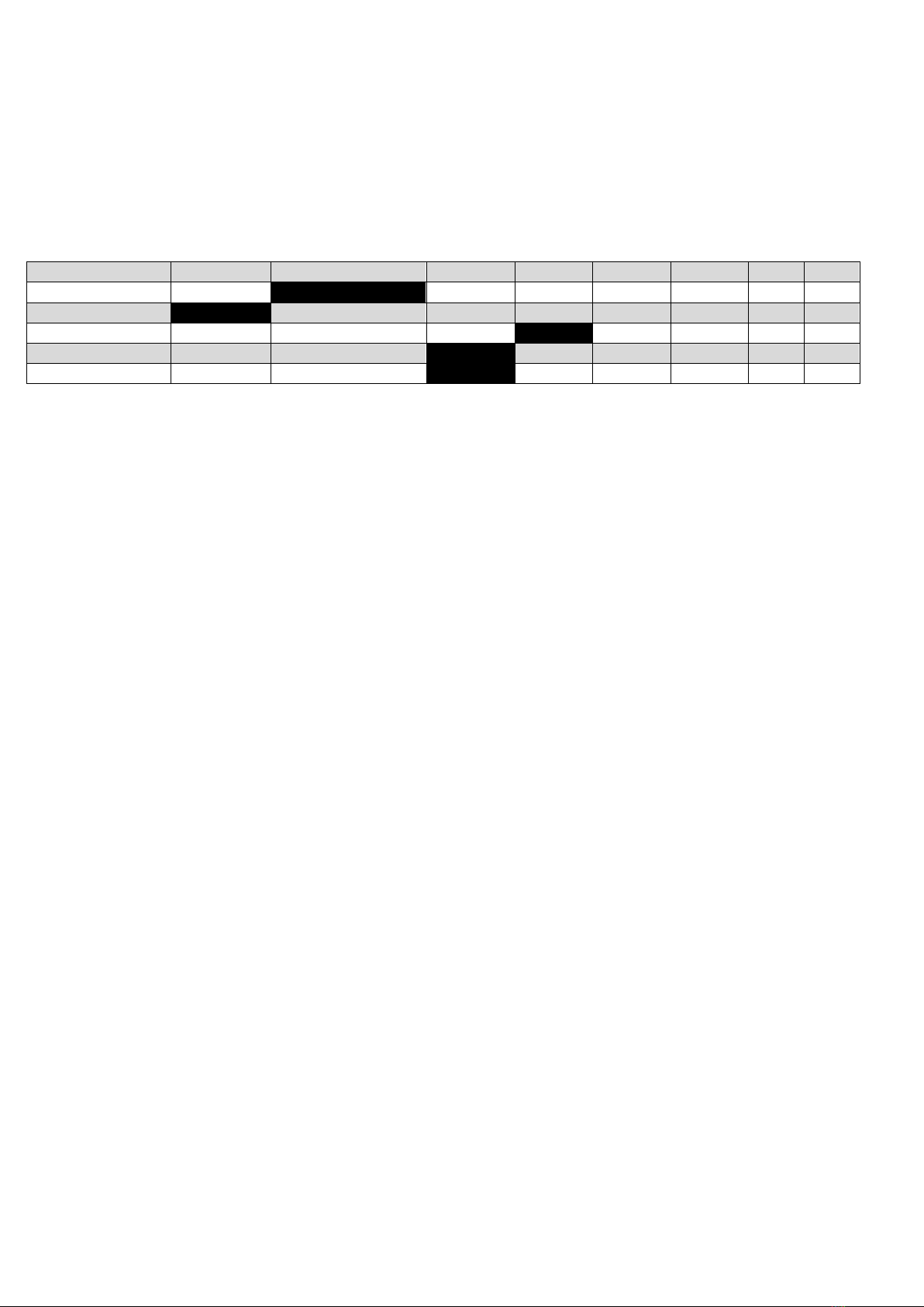
Programmierbare Einstellungen
Die schwarz unterlegten Felder zeigen die Werte der Werkseinstellung an.
Programmierpunkt
Opt. 1
Opt. 2
Opt. 3
Opt. 4
Opt.5
Opt. 6
Opt. 7
Opt. 8
1. Fahrmodus
Vorw./Bremse
Vorw./Bremse/Rückw.
2. Handbremsrate
0%
5%
10%
15%
20%
25%
30%
40%
3. Abschaltspannung
Aus
2,6V/Zelle
2,8V/Zelle
3,0V/Zelle
3,2V/Zelle
3,4V/Zelle
4. Start-Punch
Level 1
Level 2
Level 3
Level 4
5. Max. Bremskraft
25%
50%
75%
100%
Erklärung der einzelnen Programmierpunkte:
1. Fahrmodus (Running Mode)
Option 1: Vorwärts mit Bremse. Es ist ein Rennmodus. Nur vorwärts und Bremsfunktion.
Option 2: Vorwärts / Bremse / Rückwärts. Diese Option ist als "Trainings"-Modus bekannt. Hobbywing hat die
Methode "DOUBLE-CLICK" übernommen. Ihr Fahrzeug bremst nur das 1. Mal, wenn Sie den Gashebel vorwärts
(Bremse) drücken. Der Motor stoppt, wenn man schnell den Gashebel drückt und dann schnell ein 2. Mal drückt,
nur dann wird das Fahrzeug rückwärtsfahren. Die Rückfahrfunktion wird nicht aktiviert, wenn Ihr Fahrzeug nicht
zum Stillstand kommt. Das Fahrzeug fährt nur nach Stillstand des Motors. Diese Methode verhindert das ein
ungewolltes rückwärtsfahren oder eine Beschädigung auftritt.
2. Handbremsrate / Drag-Brake einstellen (Drag Brake Force)
Das ist der Wert der die Bremsleistung von Vollgas auf den voreingestellten Wert reduziert, wenn der Gashebel
in den Neutralbereich bewegt wird. Sie können den Wert der Bremsleistung von Stufe 1 (aus) bis Stufe 8(sehr
aggressiv) einstellen. Diese Einstellung simuliert die Motorbremswirkung eines Bürstenmotors.
3. Abschaltspannung (Low Voltage Cut-Off Threshold)
Diese Funktion wird verwendet, um einen LiPo- Akku vor Tiefentladung zu schützen. Der Regler überwacht
permanent die Akkuspannung, sollte die Spannung unter die des eingestellten Grenzwert sinken, wird der Regler
für 2 Sekunden auf 50% geschalten und innerhalb von 10 Sekunden abgeschaltet. Der Wert in der Tabelle gibt
den Wert pro Zelle an.
4. Beschleunigung (Start Mode / Punch)
Sie können die den Punch (Die Startbeschleunigung) von Stufe 1 (sehr weich) bis Stufe 4 (sehr aggressiv)
entsprechend der Strecke, der Reifen und dem Grip, einstellen. Bei einem höheren Level sollte berücksichtigt
werden, dass Sie einen Akku mit hoher Entladerate wählen, da durch die hohe Entladung das Fahrzeug sonst
beim Startvorgang stottert oder plötzlich an Leistung verliert. Falls dies der Fall ist müssen die Parameter
angeglichen werden (ev. auch die Untersetzung des Fahrzeuges verändern).
5. Max. Bremskraft (Max. Brake Force)
Der Regler bietet eine proportionale Bremsfunktion. Die Bremswirkung wird durch die Stellung des Gashebels
bestimmt. Er legt fest, welcher Prozentsatz der verfügbaren Bremsenergie bei voller Bremse angewendet wird.
Ein zu großer Wert verkürzt die Bremszeit, aber kann Ihr Ritzel und das Zahnrad beschädigen.
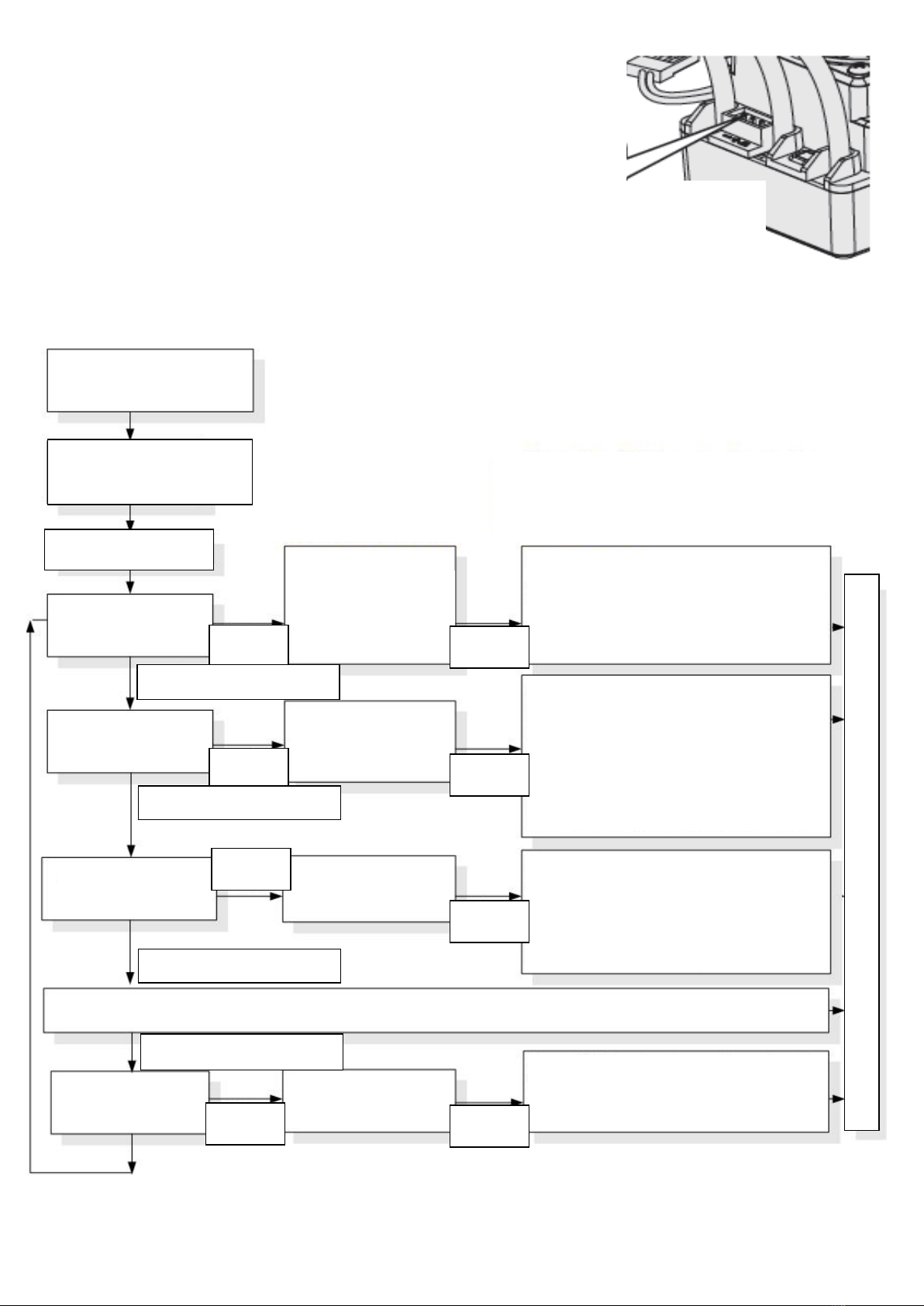
Regler-Programmierung über die Set-Taste
•Zur einfacheren Erkennung piept der Motor gleichzeitig, wenn die LED blinkt.
•Wenn "N" (die Zahl) gleich oder größer als 5 ist, verwenden wir einen langen Blitz um "5" darzustellen. Zum
Beispiel blinkt die LED einen langen Blitz (und der Motor piept mit langen Signalton zur gleichen Zeit) zeigt an,
dass Sie in der 5.Programmebene sind
•Wenn die LED einen langen Blitz und einem kurzen Blitz blinkt (und der Motor gibt einen langen Signalton und
einen kurzen Signalton gleichzeitig ab) befinden Sie sich im 6.Programmpunkt. Einen langen Blitz und zwei kurze
Blitze (ein langer Signalton und zwei kurze Signaltöne) zeigt an das Sie im 7. Programmpunkt sind usw.

5
Programmierung mit der LED-Programmierkarte
Die Programmierkarte ist separat zu erwerben. Die Benutzerfreundliche
Schnittstelle macht die Regler-Programmierung einfach und schnell.
Vor der Programmierung müssen Sie Ihren Regler mit der Programmier-Karte
über ein weißes / rotes / schwarzes Kabel mit zwei JR-Stecker verbinden.
Verbinden Sie das Kabel 1 x am Regler und das andere Ende des mit "- / + /
S" markierten Anschlusses an der Programmierkarte und schalten Sie dann
den Regler ein. Alle programmierbaren Werte werden einige Sekunden später
angezeigt. Sie können die Positionen nach Auswahl über die Schaltflächen
"ITEM" und "VALUE" auf der Programmkarte ändern. Drücken Sie die Taste
"OK", um alle neuen Einstellungen auf Ihrem Regler zu speichern.
arte
•
•
•
•
•
•
•
•
•
•
•
•
•
•
•
•
•
•
•
•
•
•
•
•Programm
Die Programmierkarte ist separat zu erwerben.
•
Externer Port zum
Anschluss der
Programmierkarte
Schalten Sie den Regler
aus und den Sender ein
Set-Knopf drücken/halten
und Regler einschalten
Rote LED blinkt
Grüne LED blinkt
einmal
Grüne LED blinkt
zweimal
Grüne LED blinkt
dreimal
Grüne LED blinkt
N-mal
Nach Drücken des Set-Knopfes
beginnt die LED zu blinken. Die
Anzahl des Blinkens zeigt an, in
welcher Auswahl Sie sich
befinden.
Drücken Sie den Set-Knopf zur Auswahl der
Option die Sie wählen möchten. Die Anzahl
des Blinkens der LED zeigt den Modus an, den
Sie wählen können.
Eingabe 1. Auswahl
„Fahrmodus“
Eingabe 2. Auswahl
„Drag Brake Force“
Eingabe 3. Auswahl
„Cut-Off“ Abschaltspg.
Rote LED blinkt 1x für Auswahl
„Vorwärts/Bremse“
Rote LED blinkt 2x für Auswahl
„Vorwärts/Bremse/Rückwärts“
Rote LED blinkt 1x für Auswahl „0%“
Rote LED blinkt 2x für Auswahl „5%“
Rote LED blinkt 3x für Auswahl „10%“
Rote LED blinkt 4x für Auswahl „15%“
Rote LED blinkt 5x für Auswahl „20%“
Rote LED blinkt 6x für Auswahl „25%“
Rote LED blinkt 7x für Auswahl „30%“
Rote LED blinkt 8x für Auswahl „40%“
Rote LED blinkt 1x für Auswahl „Aus“
Rote LED blinkt 2x für Auswahl „2,6V“
Rote LED blinkt 3x für Auswahl „2,8V“
Rote LED blinkt 4x für Auswahl „3,0V“
Rote LED blinkt 5x für Auswahl „3,2V“
Rote LED blinkt 6x für Auswahl „3,4V“
Set-Knopf
drücken
Set-Knopf
drücken
Set-Knopf
drücken
Set-Knopf
loslassen
Set-Knopf
loslassen
Set-Knopf
loslassen
← Set-Knopf 3 Sek. drücken
Set-Knopf
loslassen
….. die folgenden Schritte sind wie die oben beschriebenen jeweils um einen Schritt/Wert weiter …..
Eingabe N Auswahl
Set-Taste drücken und die jeweilige
Option wählen.
1x LED Blinken 1. Option
2x LED Blinken 2. Option …..
Set-Knopf
drücken
Zum Beenden der Programmierung den Regler aus- und wieder einschalten
Externer Port zum
Anschluss der
Programmierkarte

6
Factory Reset / Rückstellung auf Werkseinstellung
So stellen Sie die Werkseinstellungen mit der LED-Programmkarte wieder her:
Nach dem Anschließen der LED-Programmkarte an den ESC betätigen Sie die "RESET" -Taste und die "OK" -Taste,
um den ESC zurückzusetzen.
So stellen Sie die Werkseinstellungen mit der SET-Taste wieder her:
Halten Sie die SET-Taste länger als 3 Sekunden gedrückt, wenn sich der Gashebel in der neutralen Position befindet
(außer bei der ESC-Kalibrierung und -Programmierung). Die rote und grüne LED blitzen gleichzeitig kurz auf, um
anzuzeigen, dass alle Standardwerte in Ihrem ESC erfolgreich wiederhergestellt wurden. Nach Aus- und wieder
Einschalten sind die Einstellungen wieder im Werksmodus.
Troubleshooting / Fehlerbehebung
Problem
Mögliche Ursache
Lösung / Problembehebung
Nach dem Einschalten läuft der Motor
und der Lüfter nicht an.
1. Der ESC wurde nicht mit Strom
versorgt.
2. Der Schalter des ESC ist beschädigt.
1. Prüfen Sie, ob alle Verbindungen fest
verlötet oder fest angeschlossen sind.
2. Defekten Schalter ersetzen.
Nach dem Einschalten läuft der Motor
nicht an, aber der Motor gibt Signalton
im Sekundentakt ab.
Eingangsspannung nicht korrekt, zu
hoch oder zu nieder.
Prüfen Sie die Spannung des/der
Fahrakkus.
Nach dem Einschalten läuft der Motor
nicht an, aber der Motor gibt Signalton
im 2-Sekundentakt ab. D
ie rote LED
leuchtet durchgehend.
1. Der ESC erkennt kein
Gaskanalsignal.
1. Prüfen Sie ob der Gaskanal korrekt
verdrahtet ist und ob der Sender ein-
geschalten ist.
Nach dem Einschalten läuft der Motor
nicht an, die rote LED blinkt schnell.
Die Neutralstellung wurde nicht korrekt
kalibriert.
Wiederholen Sie den Kalibrierungs-
vorgang.
Das Fahrzeug bewegt sich rückwärts
beim vorwärts Gasgeben.
1. Die Verdrahtung von Regler zum
Motor ist nicht korrekt.
2. Ihr Chassis benötigt eine andere
Laufrichtung des Motors.
Tauschen Sie zwei beliebige
Motorleitungen untereinander aus.
Der Motor stoppte plötzlich oder
reduziert deutlich seine Leistung im
Betrieb.
1. Der Empfänger wurde von Störungen
beeinflusst.
2. Der LVC-
Schutz wurde aktiviert
(Abschaltautomatik/Cutoff).
1. Prüfen Sie alle Komponenten,
überprüfen Sie die Spannung des
Senders und des Fahrakkus.
2. Die rote LED blinkt, wenn der LVC-
Schutz (Unterspannungsschutz)
aktiviert ist. Prüfen Sie die Spannung
des Fahrakkus.
Das Fahrzeug fährt vorwärts aber nicht
rückwärts.
1. Die Gaskanal-Neutralstellung am
Sender ist im Bremsbereich.
2. Es ist vorwärts/Bremse
programmiert.
3. Der ESC ist defekt.
1. Die Neutralstellung des Gaskanals
neu kalibrieren. In Neutralstellung darf
keine LED am ESC aufleuchten.
2. ESC auf vorwärts/Bremse/rückwärts
umprogrammieren.
3. Kontaktieren Sie Ihren Händler für
Reparatur oder Austausch.
Das Fahrzeug fährt langsam vorwärts
oder rückwärts, wenn sich der Gas-
hebel in der Neutralstellung befindet.
Die Neutralstellung/der Gasweg wurde
nicht richtig kalibriert.
Kalibrieren Sie die Neutralstellung/den
Gasweg neu.

7
RAZER 3652 Motor
Achtung: Dies ist ein extrem leistungsfähiges Brushless-Motor-System. Zu Ihrer Sicherheit und der Sicherheit der
Personen um Sie herum, wird dringend empfohlen das Ritzel am Motor zu entfernen, bevor Sie mit der
Programmierung und Kalibrierung beginnen. Ebenso ist es ratsam bei Inbetriebnahme die Räder in der Luft zu
lassen, also ohne Bodenkontakt, wenn Sie den Regler einschalten.
Warnhinweise
•Lassen Sie das Produkt niemals unbeaufsichtigt, wenn es in Betrieb ist.
•Zur Vermeidung von Kurzschlüssen ist darauf zu achten, dass alle Drähte und Anschlüsse gut isoliert sind, bevor
Sie an den Motor/Regler anschließen.
•Vergewissern Sie sich, dass alle Komponenten ordnungsgemäß angeschlossen sind um Schäden an den
elektrischen Komponenten zu vermeiden.
•Lesen Sie die Bedienungsanleitung aller stromführenden Komponenten sorgfältig durch und stellen Sie sicher,
dass die Konfiguration der Komponenten auf einander angestimmt ist.
•Verwenden Sie zum Löten der Anschlüsse einen Lötkolben mit einer Leistung von mindestens 60 Watt.
•Halten Sie das Fahrzeug nicht in der Luft und geben Vollgas. Die Gummi-Reifen vergrößern sich durch den
fehlenden Widerstand extrem und können unter Umständen platzen, was schwere Verletzungen verursachen
kann.
•Den Gebrauch und Betrieb stoppen, sobald das Gehäuse des Motors 90 °C übersteigt, da dies den Motor
beschädigen kann da die Magnete bei Übertemperatur entmagnetisiert werden.
Technische Daten/Verkabelung
RAZER 3652SL Combo
Motor Einzelartikelnummer
R01250
R01230
R01251
R01231
R01252
R01232
R01253
R01233
Leerlaufdrehzahl 3000kV 3250kV 4000kV 4600kV
Innenwiderstand 0,0126Ω 0,0126Ω 0,0063Ω 0,0059Ω
Abmessungen
D=35mm, L=52mm
Wellendurchmesser D=3,175mm, L=15mm
LiPo / NiMH Zellen 2-3S LiPo 2S Lipo
Pole 4
Gewicht (mit Kabel) 198g 204g 207g 200g
Anwendung 1/10 Onroad, Buggy, 2WD, leichte SCT/Truck/Monster Truck
Montage des Motors in ein RC-Fahrzeug
Der Motor wird mit M3-Schrauben befestigt, die Befestigungslöcher sind 5mm tief. Wir empfehlen daher keine M3-
Schrauben mit einer Länge von mehr als 8mm zu verwenden, um den Motor nicht zu beschädigen. Bitte wählen Sie
die richtigen Befestigungsschrauben gemäß Ihrem Chassis.
Anschluss des Motors an einen ESC
Es gibt keine Polarität an den drei A/B/C Kabeln, also machen Sie sich keine Sorgen darüber, wie Sie diese
anfänglich verbinden. Wenn der Motor in die falsche Richtung läuft, müssen Sie nur zwei Drähte untereinander
vertauschen. Überprüfen Sie die Installation und alle Verbindungen nochmals, bevor Sie den Motor in Betrieb
nehmen.

8
Übersetzungsverhältnis
Es ist wichtig, dass FDR / Übersetzungsverhältnis richtig zu wählen, da ein falsches FDR / Übersetzungsverhältnis
zu Temperaturproblemen und Beschädigungen führen kann. Bitte bestimmen Sie daher die Getriebeübersetzung
anhand der folgenden Punkte!
Betriebstemperatur des Motors
Die Motortemperatur sollte während des Betriebs niedriger als 90°C sein. Temperaturen über 90°C schwächen bzw.
entmagnetisieren die Magneten und können die Spulen und den ESC beschädigen (wegen hoher Ströme). Daher
ist es extrem wichtig das richtige Übersetzungsverhältnis zu wählen.
Prinzipieller Vorgang der Auswahl des Übersetzungsverhältnisses
Um potenzielle Risiken wie ESC / Motorschäden oder Fehlfunktionen aufgrund von Überhitzung zu vermeiden,
beginnen Sie bitte mit einem sehr kleinen Ritzel und überprüfen Sie die ESC- und Motortemperatur während des
gesamten Laufs regelmäßig. Nur so kann gewährleistet werden, dass der Motor nicht überhitzt. Wenn die Motor- und
die ESC-Temperatur im Lauf stabil und niedrig bleibt, können Sie die Ritzelgröße (Zähneanzahl) langsam erhöhen
aber gleichzeitig die Temperatur weiter überwachen, um die richtige Übersetzung für Ihr Fahrzeug, das Einsatzgebiet
und den Streckenzustand zu bestimmen. Da sich diese Punkte von Strecke zu Strecke unterscheiden, sollte dieser
Vorgang immer wiederholt werden, um Ihre Elektronik vor Schäden zu schützen.
Konformitätserklärung
Hiermit erklärt der Hersteller, dass sich das Produkt in Übereinstimmung mit den grundlegenden Anforderungen und
den übrigen einschlägigen Bestimmungen der EU Richtlinien befindet. Die Konformitätserklärung ist unter
www.robitronic.com abrufbar.
Haftungsausschluss
Da die Einhaltung der Bedienungsanleitung, sowie der Betrieb und die Bedingungen bei Verwendung des Produktes
zu keiner Zeit vom Hersteller überwacht werden kann, übernimmt der Hersteller keinerlei Haftung für Schäden,
Kosten und/oder Verluste, die sich aus falscher Verwendung und/oder fehlerhaftem Betrieb ergeben oder in
irgendeiner Weise damit zusammenhängen.
Entsorgung
Elektronische Altgeräte sind Rohstoffe und gehören nicht in den Hausmüll. Ist das Produkt am Ende seiner
Lebensdauer, so entsorgen Sie dieses gemäß den geltenden gesetzlichen Vorschriften bei Ihren
kommunalen Sammelstellen. Eine Entsorgung über den Hausmüll ist verboten.
Garantiebestimmungen
Mit dem Erwerb dieses Produktes haben Sie gleichzeitig eine zweijährige Garantie ab Kaufdatum erworben. Die
Garantie gilt nur für die bereits beim Kauf des Produktes vorhandenen Material- und/oder Funktionsmängel.
Von der Garantie ausgeschlossen sind:
•Schäden durch falsche Anwendung
•Schäden durch Vernachlässigung der Sorgfaltspflicht
•Schäden durch unsachgemäße Behandlung und Wartungsfehler
•Flüssigkeitsschäden
Bei Garantiefällen wenden Sie sich bitte an ihren Fachhändler.
Sollte es notwendig sein das Produkt einzusenden, legen Sie bitte unbedingt eine Kopie der Rechnung und einen
Reparaturauftrag bei. Diesen können Sie unter www.robitronic.com herunterladen. Bei direkter Zusendung an die
Serviceabteilung muss vorher Rücksprache (telefonisch oder per E-Mail) gehalten werden. Die Portokosten trägt der
Versender. Kostenpflichtige Pakete werden nicht angenommen. Jeder eingesendete Garantiefall wird zunächst
durch unsere Serviceabteilung auf Zulässigkeit geprüft. Für abgelehnte Garantiefälle wird ggf. eine Kontroll- und
Bearbeitungsgebühr verrechnet bevor wir das Produkt zurücksenden. Reparaturen die nicht unter die
Garantieleistung fallen, müssen vor Beginn der Reparatur bezahlt werden.

9
Introduction
Thanks for purchasing our Electronic Speed Controller (ESC). The power system for RC model can be very
dangerous, so please read this manual carefully. In that we have no control over the correct use, installation,
application, or maintenance of our products, no liability shall be assumed nor accepted for any damages, losses or
costs resulting from the use of the product. Any claims arising from the operating, failure of malfunctioning etc. will
be denied. We assume no liability for personal injury, consequential damages resulting from our product or our
workmanship.
Features
•Completely water-proof and dust-proof. The ESC works properly even under water.
(Please remove the cooling fan when running car in water, and after running, please make the ESC clean
and then dry it to avoid the oxidation of copper connectors)
•Drive sensorless brushless motors.
•Excellent start-up, acceleration and linearity features.
•The built-in switching mode BEC has powerful output to supply all electronic equipments.
•There is a mounting stand for installing the ESC on chassis easily and firmly.
•Proportional ABS brake function with 4 steps of maximum brake force adjustment, 8 steps of drag-brake force
adjustment. Also compatible with the mechanical disc-brake system.
•Multiple protection features: Low voltage cut-off protection / Over-heat protection / Throttle signal loss protection
/ Motor blocked protection
•Easily programmed with the SET button of the ESC, and also compatible with pocket-sized Program Card.
Warning notes
•To avoid short circuits, make sure that all wires and connections are well insulated before connecting the regulator.
•Make sure all components are properly connected to prevent damage to the electrical components.
•Read the operating instructions of all live components carefully and make sure that the configuration of the
components is attuned to each other.
•Use a soldering iron with a capacity of at least 60 watts to solder all input / output lines and connections.
•Do not hold the vehicle in the air and give full throttle. The rubber tires increase in size due to the lack of resistance
and can potentially burst, which can cause serious injury.
•Stop use and operation as soon as the controller housing exceeds 90 ° C, as this may damage both the controller
and the motor. The factory overheat protection is set to 105 ℃(this corresponds to the internal temperature of the
controller).
•Always disconnect the battery from the regulator after use. The permanent connection of a battery to the controller
over a longer period of time can lead to damage and / or deep discharge of the battery or regulator. This is NOT
covered by the warranty.

10
Specifications
RAZER ten 50A
R01221 // R01250
Cont./Burst Current
50A / 300A
Motortype
Sensorless Motors
Cars Applicable
1/10 Onroad and Offroad
Motorlimit
2S Onroad: 3650er Motor, ≥8T; 3S Onroad: 3650er Motor, ≥11T
2S Offroad: 3650er Motor, ≥11T; 3S Offroad: 3650er Motor, ≥14T
Resistance
0,0010Ohm
LiPo / NiMH Battery
2-3S LiPo / 6-9 cells NiMH
S-BEC Output
6V, 3A (The cooling fan is always working under 6V)
Programming-Port
Fan-/Prog port on ESC
Dimensions
48,5 x 38 x 32 mm
Weight
90g
RAZER ten 60A
R01222 // R01251 / R01252 / R01253
Cont./Burst Current
60A / 390A
Motortype
Sensorless Motors
Cars Applicable
1/10 Onroad and Offroad
Motorlimit
2S Onroad: 3650er Motor, ≥5,5T; 3S Onroad: 3650er Motor, ≥9T
2S Offroad: 3650er Motor, ≥8,5T; 3S Offroad: 3650er Motor, ≥13T
Resistance
0,0012Ohm
LiPo / NiMH Battery
2-3S LiPo / 6-9 cells NiMH
S-BEC Output
6V, 3A (The cooling fan is always working under 6V)
Programming-Port
Fan-/Prog port on ESC
Dimensions
48,5 x 38 x 32 mm
Weight
90g
Connection
Warning:This is a real powerful Brushless-Motor-System. For safety, remove for setup the pinion and please always
keep the wheels away from the track when switching on the ESC.

11
•Connecting the motor:
The #A, #B, #C wires of the ESC can be connected with the motor wires freely (without any sequence). If the
motor runs in the opposite direction, please swap any two wire connections.
•Connecting the receiver:
Plug the gas channel cable on the controller into the TH / Gas channel on the receiver. The gas channel cable
outputs the voltage of 6V to the receiver and the steering servo. Be careful not to connect a separate battery to
the receiver, otherwise your ESC may be damaged.
•Connecting the battery:
Proper polarity is extremely important. Please make sure that the plus (+) is connected to plus (+) and minus (-)
is connected to negative (-) of the battery. Reversing the polarity on your regulator from the battery will damage
your regulator, which is NOT covered by the warranty!
Throttle Range Setting (Throttle Range Calibration)
In order to make the ESC match the throttle range, you must calibrate it when you begin to use a new ESC, or a new
transmitter, or change the settings of neutral position of the throttle stick, ATV or EPA parameters, etc.
The following pictures show how to set the throttle range with a FutabaTM transmitter.
1. Switch off the ESC, turn on the transmitter, set the direction of throttle channel to ”REV”, set the “EPA/ATV”
value of throttle channel to “100%”, and disable the ABS function of your transmitter.
2. Hold the “SET” key and then switch on the ESC, and release the “SET” key as soon as possible when the red
LED begins to flash.
Note: If you don’t release the “SET” key as soon as the red LED begins to flash, the ESC will enter the program
mode, in such a case, please switch off the ESC and re-calibrate the throttle range again from step A to step
D.
3. Set the 3 points according to the steps
shown in the pictures on the right side.
1) The neutral point
Move the throttle stick at the neutral
point, and then click the SET key, the
green LED flashes 1 time.
2) The end point of forward direction
Move the throttle stick at the end point of
forward direction, and then click the SET
key, the green LED flashes 2 times.
3) The end point of backward direction
Move the throttle stick at the end point of
backward direction, and then click the
SET key, the green LED flashes 3 times..
4. Throttle range is calibrated; motor can be
started after 3 seconds

12
Check LED Status In Normal Running
•When the throttle stick is in the neutral range, neither the Red LED nor the Green LED lights up.
•When the car moves forward, the Red LED solidly lights; the Green LED also lights up when the throttle stick is
at the top position (100% throttle).
•When the car brakes, the Red LED solidly lights; the Green LED also lights up when the throttle stick is at the
bottom position and the maximum brake force is set to 100%.
•When the car reverses, the Red LED solidly lights.
Programmable Items List
The black highlighted fields show the values of the factory setting:
Programmable items
Opt. 1
Opt. 2
Opt. 3
Opt. 4
Opt.5
Opt. 6
Opt. 7
Opt. 8
1. Running Mode
Forw./Brake
Forw./Rev. w. Brake
2. Drag Brake Force
0%
5%
10%
15%
20%
25%
30%
40%
3. Low Voltage
Cut-Off Threshold Off 2,6V/Cell 2,8V/Cell 3,0V/Cell 3,2V/Cell 3,4V/Cell
4. Start Mode(Punch) Level 1 Level 2 Level 3 Level 4
5. Max Brake Force 25% 50% 75% 100%
Explanation of programmable items:
1. Running Mode
In “Forward with Brake” mode, the car can go forward and brake, but cannot go backward, this mode is suitable
for competition; “Forward/Reverse with Brake” mode provides backward function, which is suitable for daily
training.
Note: “Forward/Reverse with Brake” mode uses “Double-click” method to make the car go backward.
When you move the throttle stick from forward zone to backward zone for the first time (The 1st “click”), the ESC
begins to brake the motor, the motor speeds down but it is still running, not completely stopped, so the backward
action is not happened immediately. When the throttle stick is moved to the backward zone again (The 2nd “click”),
if the motor speed is slowed down to zero (i.e. stopped), the backward action will happen. The “Double-Click”
method can prevent mistakenly reversing action when the brake function is frequently used in steering. By the
way, in the process of braking or reversing, if the throttle stick is moved to forward zone, the motor will run
forward at once.
2. Drag Brake Force
Set the amount of drag brake applied at neutral throttle to simulate the slight braking effect of a neutral brushed
motor while coasting.
3. Low Voltage Cut-Off Threshold
The function is mainly used to prevent the Lipo battery from over discharging. The ESC monitors the battery’s
voltage at any time, if the voltage is lower than the threshold, the output power will be reduced to 50% in 2
seconds. Please drive to the side of racing track as soon as possible and then stop the car, the ESC will
completely cut off the output power in 10 seconds. The values listed in the table refer to the cut-off threshold for
each Lipo cell. If you use the NIMH battery ,the output power will be reduced when the input voltage is
lower than 5V .
4. Start Mode / Punch
Select from “Level1 (Soft)” to “Level 4(Very aggressive)” start mode as you like. Please note that if you choose
“Level 4(Very aggressive)”, you should use good quality battery with powerful discharge ability, otherwise you
cannot get the bursting start effect as you want. If the motor cannot run smoothly (that is: the motor is trembling),
it may caused by the weak discharge ability of the battery, please choose a better battery or increase the gear
rate.
5. Max. Brake Force
The ESC provides proportional brake function. The brake force is related to the position of the throttle stick.
Maximum brake force refers to the force when the throttle stick is located at the end point of the backward zone.
A very large brake force can shorten the brake time, but it may damage the gears.

13
Program the ESC with the SET button on the ESC
•For easier detection, the motor beeps simultaneously when the LED is flashing.
•If "N" (the number) is equal to or greater than 5, we use a long flash to represent "5". For example, the LED flashes
a long flash (and the engine beeps with a long beep at the same time) indicating that you are in the 5th program
level
•If the LED flashes a long flash and a short flash (and the engine emits a long beep and a short beep at the same
time), you are in the 6th program point. A long flash and two short flashes (one long beep and two short beeps)
indicate that you are in the 7th program, and so on.
Program the ESC with the LED program box
The Program Card is optional equipment which needs to be purchased separately.
It has 3 digital LEDs to display the programmable items’ number and the options’ number.
(Please refer to the user manual of the program card for detail info). The
user-friendly interface makes the controller programming easy and fast.
Before programming, you must connect your controller to the
programming card via a white / red / black cable with two JR plugs.
Connect the cable 1 x to the controller and the other end of the "- / + /
S" marked port on the programming card and then turn on the controller.
All programmable values are displayed a few seconds later. You can
change the positions after selection using the "ITEM" and "VALUE"
buttons on the program card. Press the "OK" button to save all new
settings to your controller.

14
Factory Reset / Reset All Items To Default Values
At any time when the throttle is located in neutral zone (except in the throttle calibration or parameters program
process), hold the “SET” key for over 3 seconds, the red LED and green LED will flash at the same time , which
means each programmable item has be reset to its default value. It needs to be restarted to complete the whole
process.
How to restore the factory settings with the LED program card:
After connecting the LED program card to the ESC, press the "RESET" button and the "OK" button to reset the ESC.
Troubleshooting
Trouble
Possible Reason
Solution
After power on, motor can’t work, no sound
is emitted
The connections between battery pack and
ESC are not correct
Check the power connections
Replace the connectors
After power on, motor can’t work, but emits
“beep-beep-, beep-beep-” alert tone. (Every
“beep-beep-” has a time interval of 1 second
)
Input voltage is abnormal, too high or too
low.
Check the voltage of the battery pack
After power on, motor can’t work, but emits
“beep-, beep-, beep-”
alert tone. (Every
“beep-”
has a time interval of about 2
seconds). And the red LED solid lights
Throttle signal is abnormal
Check the transmitter and the receiver
Check the wire of the throttle channel
After power on, motor can’t work and the red
LED blinks very quickly
The neutral point of the throttle channel is
changed
Calibrate the throttle range for the ESC
again, or adjust
the trimmer of throttle
channel (on the transmitter) to change the
neutral point.
The motor runs in the opposite direction
The wire connections between ESC and the
motor need to be changed
Swap any two wire connections between the
ESC and the motor.
The motor suddenly stops running while in
working state
The throttle signal is lost
Check the transmitter and the receiver
Check the wire of the throttle channel
The ESC has entered the Low Voltage
Protection Mode
Replace the battery pack
Random stop or restart or irregular working
state
Some connections are not reliable
Check all the connections: battery pack
connections, throttle signal wire, and motor
connections, etc.
There is strong electro - magnetic
interference in drive area.
Reset the ESC. If the function could not be
resumed, you might need to move to another
area to run the car.

15
RAZER 3652 Motor
Warnings
•Never leave this product unsupervised when it is powered on.
•Ensure all wires and connections are well insulated before connecting the motor to related devices, as short circuit
will damage your motor.
•Make sure all components are properly connected to prevent damage to the electrical components.
•Read through the manuals of all power devices and chassis and ensure the power configuration is rational before
using it. Never hit full throttle without installed pinion, no load may cause damage the motor.
•Use a soldering iron with a capacity of at least 60 watts to solder the connections.
•Do not hold the vehicle in the air and give full throttle. The rubber tires are extremely enlarged due to the lack of
resistance and can possibly be damaged. burst, which can cause serious injury.
•Stop using the motor as soon as the motor housing exceeds 90°C, otherwise the rotor may be demagnetized and
cause irreversible damage to the motor when overtemperature occurs.
Specifications/Connection
How to Mount the Motor into a RC vehicle
M3 mounting screws are needed here, and as the mounting holes are 5mm in depth, so we don’t recommend using
the M3 screws with the length exceeds 8mm to mount the motor into your vehicle. Please choose the right mounting
screws as per your chassis.
How to Connect the Motor to an ESC
There is no polarity on the three A/B/C ESC-to-motor wires, so do not worry about how you connect them initially.
You may find it necessary to swap two wires if the motor runs in reverse direction.
Recheck the Installation & Connections
Recheck the installation and all the connections before turning on the power.
FDR/Gear Ratio Selection
It’s important to select the FDR/gear ratio properly, as improper FDR/gear ratio may cause you great loss. Therefore,
please choose the gear ratio by referring to the following points!
Operating Temperature of the Motor
The motor temperature should be lower than 90°C (194°F)during the operation. Temperatures above 90°C will
weaken the magnet and may partly melt the coils and eventually damage the ESC (because of strong current).
Therefore, the most effective way to prevent overheat is to select the right gear ratio.
RAZER 3652SL Combo
Motor Part number
R01250
R01230
R01251
R01231
R01252
R01232
R01253
R01233
KV no load
3000kV
3250kV
4000kV
4600kV
Inner resistance
0,0126Ω
0,0126Ω
0,0063Ω
0,0059Ω
Dimensions
D=35mm, L=52mm
Shaft diameter
D=3,175mm, L=15mm
LiPo cells
2-3S LiPo
2S Lipo
Pole
4
Weight (with cable)
198g
204g
207g
200g
Applicable
1/10th Buggy, On-road, and Light-weight 2WD SCT/Truck/Monster Truck

16
Principle of Gear Ratio Selection
To avoid potential risks such as ESC/motor damage or malfunction caused by overheat, please start with a very
small pinion first and check the ESC & motor temperatures regularly throughout the run. This is the only way to
guarantee that your motor won’t overheat. If the motor and ESC temperatures remain stable and low in the running,
then you can slowly increase the pinion size while monitoring temperatures to determine the safe gearing for your
vehicle, climate and track condition. Because these elements may change, so please keep monitoring the ESC &
motor temperatures to protect your electronics from damage.
Declaration of Conformity (DOC)
Hereby, the manufacturer declares that this product is in compliance with the essential requirements and other
relevant provisions of EU Directives. The declaration of conformity may be consulted at www.robitronic.com
Disclaimer
Da die Einhaltung der Bedienungsanleitung, sowie der Betrieb und die Bedingungen bei Verwendung des Produktes
zu keiner Zeit vom Hersteller überwacht werden kann, übernimmt der Hersteller keinerlei Haftung für Schäden,
Kosten und/oder Verluste, die sich aus falscher Verwendung und/oder fehlerhaftem Betrieb ergeben oder in
irgendeiner Weise damit zusammenhängen.
Disposal of Electronic Waste
Electronic waste is a commodity and must be disposed through special electronic waste sites. Please inform
yourself about adequate facilities in your community area. Disposal of this product through domestic waste is
illegal.
Warranty
With the purchase of this product you purchased at the same time a two-year warranty from date of purchase. The
guarantee applies only to the already existing material defects on the purchase of the product and / or functional
defects. Excluded from the guarantee are:
•Damage caused by incorrect use
•Damage caused by neglect of duty of care
•Damage caused by improper handling and maintenance errors
•Liquid damage
For warranty claims, please contact your local dealer.
Should it be necessary to send the product, you must enclose a copy of the invoice and a repair order. You can
download it at www.robitronic.com. With direct sending to the service department must be consulted beforehand
(held by telephone or e-mail). The postage costs borne by the consignor. Paid packages are not accepted. Everyone
sent in warranty case is first examined by our service department on admissibility. For reject warranty claims will be
charged back to a control and processing fee before we return the product. Repairs not covered under warranty,
before the start of the repair must be paid.
Technical specifications, features and design are subject to change.
.
Robitronic Electronic GmbH
Pfarrgasse 50, 1230 Wien
Österreich
Tel.: +43 (0)1-982 09 20
Fax.: +43 (0)1-98 209 21
www.robitronic.com
This manual suits for next models
6
Table of contents
Languages:
Other Robitronic Engine manuals
Popular Engine manuals by other brands

Siemens
Siemens SIMOTICS S-1FK7 DYA Generation 2 operating instructions

Sole Diesel
Sole Diesel SK-60 Operator's manual

Toro
Toro LAWN-BOY Series Service manual

Europa Aircraft
Europa Aircraft Rotax 914 installation manual

Leroy-Somer
Leroy-Somer VARMECA 20 Parameter-setting manual

Yanmar
Yanmar 3JH4E Operation manual