ROBO Cylinder RCA-P User manual

Robo Cylinder Data Input Pendant
RCA-P
Operating Manual
Ver. 4.0
IAI Corporation

Table of Contents
1. Foreword.................................................................................................................................................... 1
2. Before You Begin....................................................................................................................................... 1
3. Safety Precautions..................................................................................................................................... 2
4. Warranty and Scope of Warranty ............................................................................................................... 3
5. Application Environment ............................................................................................................................ 4
6. Functions and Specifications of Data Input Pendant.................................................................................. 5
6-1 Specifications...................................................................................................................................... 5
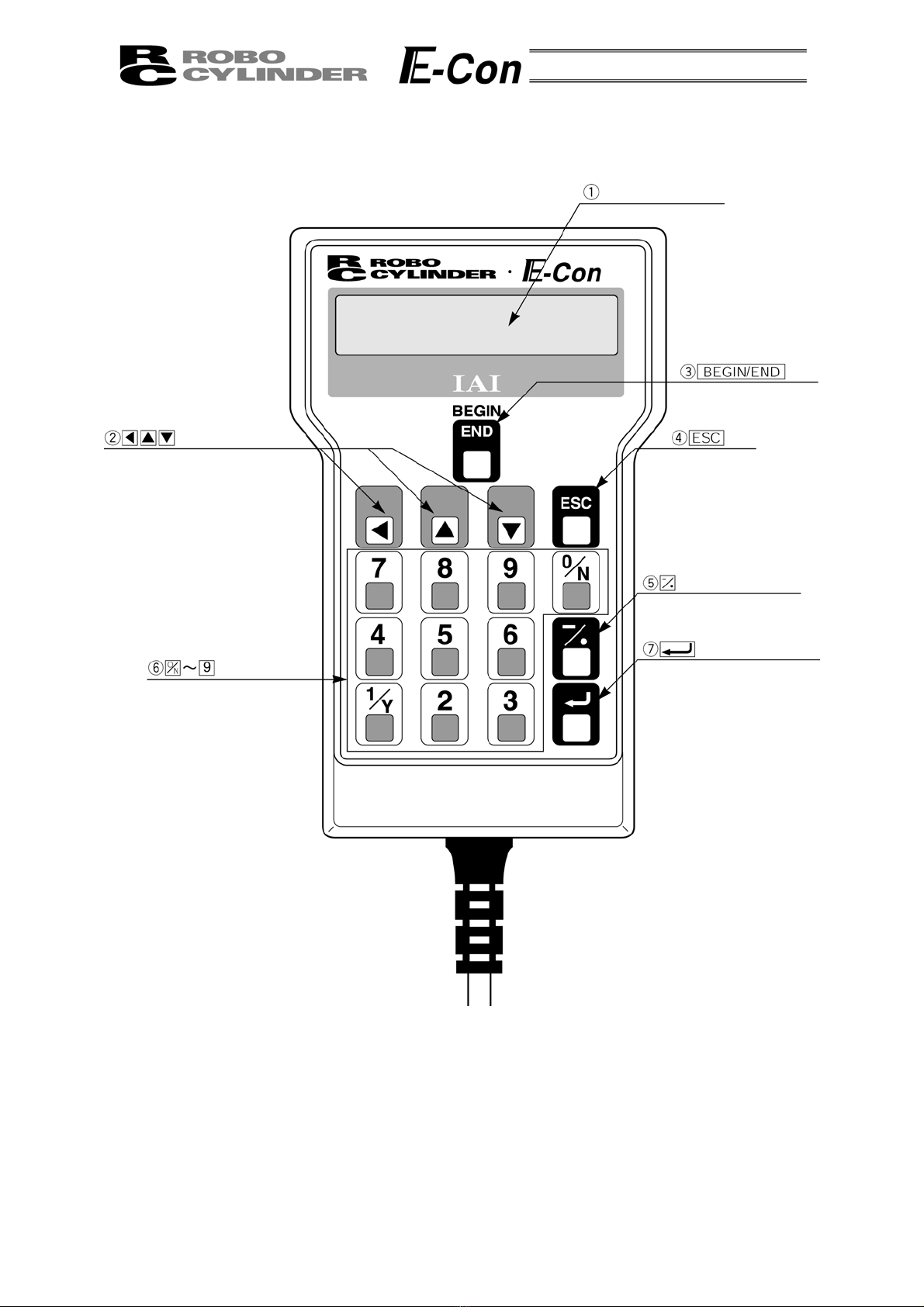
6-2 External View ...................................................................................................................................... 6
6-3 Description of Each Part ..................................................................................................................... 7
7. Connection With the Controller .................................................................................................................. 9
7-1 Connection with the Data Input Pendant............................................................................................. 9
7-2 How to Disengage the Data Input Pendant......................................................................................... 9
8. Operation ................................................................................................................................................. 10
8-1 Initial Screen During Power - UP ...................................................................................................... 12
8-2 Controller Selection (when using multiple units) ............................................................................... 13
8-3 Operation Mode Selection ................................................................................................................ 14
8-4 Edit/Teaching.................................................................................................................................... 15
8-4-1 Edit/Teach Screen ..................................................................................................................... 15
8-4-2 Position Data Table ................................................................................................................... 16
8-4-3 Data Input .................................................................................................................................. 19
8-4-5 Add • Delete............................................................................................................................... 24
8-4-5 Data Modification ....................................................................................................................... 29
8-5 Monitor.............................................................................................................................................. 30
8-6 Error List ........................................................................................................................................... 31
8-7 User Parameter................................................................................................................................. 32
8-8 User Adjustment ............................................................................................................................... 34
8-9 End ................................................................................................................................................... 35
9. Message Area.......................................................................................................................................... 36
9-1 Warning Label Error (Code No. 000h – 07Fh) .................................................................................. 36
9-2 Data Input Pendant Message Level Error ......................................................................................... 37
9-3 Controller Error ................................................................................................................................. 37

1. Foreword
Thank you very much for purchasing the Data Input Pendant (RCA-P) for the Robo Cylinder Controller.
Without knowing beforehand how to correctly use or operate the Data Input Pendant, not only will the user be
unable to take full advantage of all the functions built into this product but the user might also inadvertently
cause damage to the Controller or shorten its life. Please read this manual carefully as well as other manuals
pertaining to the product to acquire an understanding of the proper method of handling and operating the
controller. Keep this manual handy so that you can refer to the appropriate sections as the need arises.
For the actuator and controller to be used, be sure to refer to the Instruction Manuals attached to the
products.
Caution: Do not edit position data while the actuator is operating by PLC, etc.
Also, do not edit any position number not actually operated.
2. Before You Begin
(1) Please read this manual carefully to operate the controller properly.
(2) You are not allowed to reproduce this manual or any portion thereof without permission.
(3) For any handling and operating methods other than those described in this Instruction Manual,
interpret them as “don’t” or “can’t.”
(4) We cannot accept any responsibility for possible damage resulting from the use of this manual.
(5) We reserve the right to change the information contained in this manual without prior notice.
1

3. Safety Precautions
(1) Use a genuine product specified by us for wiring between the actuator and controller.
(2) Stand clear of the operating range of the machine when it is in motion or is ready to operate. Surround
the system with safety partitions if there is a possibility that people can enter the area where the machine
is being used.
(3) When assembling, adjusting, or performing maintenance on the machine, always disengage the power
supply to the controller. During work, display a sign stating work in progress where it is readily visible.
Also, keep the power cable close to the operator so that another person cannot inadvertently switch on
the power. Alternatively, lock the power plug or receptacle and direct the operator to hold the key or
prepare a safety plug.
(4) When more than one person is working on the system, agree on signals beforehand to ensure
everyone's safety before beginning work. In particular, when doing work involving axis movement,
always call out for everyone's safety regardless of whether power is ON or OFF, or the axis is to be
mechanically driven or manually moved.
(5) When the user needs to lengthen the cables, check the wiring carefully to make sure it is correct before
turning the power ON since miswiring can lead to misoperation.
2

4. Warranty and Scope of Warranty
The Data Input Pendant undergoes stringent testing before it is shipped from our factory.
IAI provides the following warranty.
1. Warranty Period
The warranty period shall be either the following period, whichever is reached first.
- 18 months after our shipment
- 12 months after delivery to the place designated by you
2. Scope of Warranty
If within the period specified above, a breakdown occurs while operating the controller under normal
conditions and is clearly the responsibility of the manufacturer, IAI will repair the unit at no cost. However,
the following items are not covered by this warranty.
- Faded paint or other changes that occur naturally over time.
- Consumable components that wear out (such as a cable).
- Unit seems to be noisy or similar impressions that do not affect machinery performance.
- Damage resulting from improper handling or use.
- Damage resulting from user error or failure to perform proper maintenance.
- Damage resulting from the use of any part other than our genuine parts.
- Any alterations not authorized by IAI or its representatives.
- Damage caused by fire and other natural disasters or accidents.
The warranty pertains to the purchased product itself and does not cover any loss that might arise from a
breakdown of the product. Any repairs will be done at our factory.
3. Service
The purchase price of the product does not include programming or expenses for sending technicians to
the customer's site. Even if the product is still under the warranty period, separate charges will be assessed
for the following services.
- Inspection and maintenance.
- Technical guidance and technical training in operating instructions.
- Technical guidance and technical training on program-related matters such as program creation.
3

5. Application Environment
- In order to avoid breakdown, please do not apply any type of machinery impact onto the Data Input
Pendant.
- Always hold onto the entire Data Input Pendant Body so that the Data Input Pendant Cable does not
get pulled by unwanted cables.
Caution: This Data Input Pendant is designed exclusively for the IAI RC
Controller, and should not be used to connect with other devices.
Caution: Regarding controller connection, please turn the controller front side port
switch OFF before connecting to the controller.
4

6. Functions and Specifications of Data Input Pendant
Through the communication between the controller, the RC Data Input Pendant is designed to function
as the Display Operation Unit to edit or display the data (common data, move point data, etc.,) that is stored
inside the controller.
It cannot be used for any operation related to axis movement.
LCD: Horizontal 16 characters Vertical 2 lines
6-1 Specifications
Item Specification
Ambient Temperature & Humidity Temperature: 0°~40°C Humidity: 85% RH or less
* RH relative humidity
Operating Environment Free of corrosive gas, especially, no excessive dust
Weight 380g
Cable Length 5m
5

6-2 External View
External Dimensions
6

6-3 Description of Each Part
LCD Display
Key
A
rrow Keys Key
Minus Key
Return Key
Numeric Key
7

(1) LCD Display
This is a liquid crystal display with a maximum of horizontal: 16 characters per column, and vertical: 2
columns per row.
This displays edit and teaching contents of various set values.
(2) Arrow Key
- This is used for selection of the mode, the contents of data and changing position No.
(3) Key
- Execution of Data Input Pendant configuration or axis reconnection.
By pressing this key for more than 2.5 seconds, the screen will change into the “BEGIN/END” screen
and you will be able to reconnect the axis and execute Data Input Pendant configuration.
- If entering data via key pad, you may cancel midway using this key.
- You may clear error warning.
- When an error occurs, a message for this error will appear at the very bottom of the display screen.
Use this key to clear the error and to clear this message.
(4)
ESC
Key
- Return to the display of a previous screen
The Data Input Pendant operation has a several-layer nested structure. Using this key can return the
user to one layer above (previous screen).
When you don’t understand the operation, undo the operation by pressing the ESC Key.
(5) (Minus) Key
- Position Table Column: When you push this in an area such as positioning width which allows minus
input, the key functions as the “-” (minus), and the rest as “.” (point). When you input either or
in the beginning of the number, within the proper area, the key will automatically recognize it as 0.
(6) (Numeric) Key
- This key is used for numeric input.
(7) (Return) Key
- This is used for data input and operation confirm.
8

7. Connection With the Controller
7-1 Connection with the Data Input Pendant
(1) Connect the Data Input Pendant Cable to the “PORT IN” connector which is located on the front of the
controller. Always turn OFF the controller Port Switch first before connecting.
(In a case of ERC, there is no Port Switch, please power off the unit.)
PORT switch
PORT IN connector
(2) After connecting, turn the controller PORT Switch ON.
7-2 How to Disengage the Data Input Pendant
Hold down the BEGIN/END Key which is located in the upper of the key pad. Select “Complete” to
finish. Afterwards, turn the controller front SW side to OFF, and remove the Data input pendant
connector.
Operation:
1. Hold down the BEGIN/END Key for more than 2.5 seconds.
2. Use the Arrow Key to select “Complete” Screen, and then press the Return Key.
3. Turn the RC Controller PORT SW OFF.
4. Remove the Data Input Pendant connector.
9

8. Operation
The Data Input Pendant operation has the following overall tree structure.
The menus in this tree structure differ according to the controller type/version or Data Input Pendant
version. For details, refer to the Instruction Manual of each controller. The following indicates the case of
ERC.
Power-ON
Reconnect
Confirming connection
Return Return
Return Return
Mode Select
Axis Select
(1) Position
(2) Speed
(3) ACC • DEC
(4) Push Power
(5) Positioning
(6) Rated speed only MAX
(7) ABS / INC
Edit / Teach
Operation
Start/End
(2) Add
(3) Delete
(4) Clear
(5) All Clear
(6) Direct Teach
End
* You will be able to change to the
“Operation Start/End” screen from
any other screen by using
BEGIN/END key.
Please, press BEGIN/END key for
more than 2.5 seconds.
Incorporate
Monitor
*1: The menu descriptions are as
shown on the following page
according to the PIO pattern.
Error List
(1) Error No.
(2) Message
(3) Axis No.
(4) __Minutes ago occurrence
*2
10

*2 *1
3 Position Type
(PIO:1)
8 Position Type
(PIO:0)
Position
Error No.
Servo ON
in ST0
in ST1
in ST2
in_STP
out PE0
out PE1
out PE2
out_ALM
CTL Ver
(1) + Zone
(2) - Zone
(3) + Limit
(4) - Limit
(5) Home
Return
(6) Reset speed
Return
(7) Reset ACC • DEC
(8) Reset range
(9) Acceleration MAX
(10) Push stop determined
(11) Servo gain
(12) Current stop
(13) Home current
(14) Temporary stop not effect
(15) Baud rate
(16) PTIM
(17) Offset
(18) PIO pattern
(19) Move instruction type
Position
Error No.
Servo ON
in START
in Position No.
in_STP
in_HOME
out PEND
out HEND
out ZONE
out_ALM
CTL Ver
User Parameter
Monitor
(1)
(2)
(3)
(4)
(5)
(6)
(7)
(8)
(9)
(10)
(11)
(12)
16 Position Type
(PIO:2)
Position
Error No.
Servo ON
in START
in Position No.
in_STP
in_PEND
out HEND
out ZONE
out_ALM
CTL Ver
(1) Adjustment No.
(2) Distribution No.
User Adjustment
Return
11

8-1 Initial Screen During Power - UP
When power is connected to the controller and the controller PORT switch is ON, power is supplied
to the Data Input Pendant and operation starts.
Upon power-on, the LCD display screen (hereinafter called the “screen”) displays the Data Input
Pendant software version as follows:
Confirming connection
IAI RC DU V.1.66
Once the controller connection has been completed, the screen automatically moves to the Mode
Select screen in a defined period of time.
12

8-2 Controller Selection (when using multiple units)
In case of multiple units connected serially via the communication line, the axis selection screen will
be displayed. For a single unit, since there is no need to select the axis, the first screen below will not
appear (refer to Section 8.3 entitled Operational Mode Selection of this manual). The content explained
here will be based on operation of the selected axis (controller). In addition, the controller can connect
up to 16 units.
Using the Keys, select the data inputting axis
(controller), and determine with the Return Key.
Only the connecting axis will be displayed.
Axis Select
* Axis No. 00
Axis Select
* Axis No. 01
A
xis number
Axis Select
* Axis No. 02
•
•
•
Caution: If power is supplied with the PORT switch ON and power is present on
the Data Input Pendant, only powered controllers will be detected.
The content explained hereinafter will be based on operation against selected axis (controller).
13

8-3 Operation Mode Selection
Mode Select Edit/Teach
Monitor
Error List
User
Parameter
User
Adjustment
Display screen
Mode Select A. 00
* User Ad
j
ustment
Mode Select A. 00
* User Parameter
Mode Select A. 00
* Error List
Mode Select A. 00
* Monitor
Mode Select A. 00
* Edit
/
Teach
For the modes, select one of the 5 options as it appears on the above screen.
To select, move the cursor to the mode desired and confirm using the Return Key.
Category of Modes
1. * Edit/Teach Edit and numeric input function for position data table
2. * Monitor RC Controller status display
3. * Error list Alarm content detailed display
4. * User Parameter Setting of axis zone signal output range and axis
5. * User Adjustment Setting for enabling or disabling of temporary stop (hold) input and actuator
integrated RC controller.
14

8-4 Edit/Teaching
8-4-1 Edit/Teach Screen
When “*Edit/Teach” is selected on the Mode Select screen, the Edit/Teach screen is displayed.
The Edit/Teach screen has the 6 items as follows:
Mode Select Edit/Teach
Monitor
Error List
User
Parameter
User
Adjustment
MDI
A
dd
Delete
Clear
A
ll Clear
Direct Teach
Edit/Teach A. 00
*
A
ll Clear
Edit/Teach A. 00
* Direct Teach
Edit/Teach A. 00
* Clear
Edit/Teach A. 00
* Delete
Edit/Teach A. 00
*
A
dd
Edit/Teach A. 00
* MDI
15

You can change the screens by using the arrow keys ( ) and press the return key.
* MDI: Numerically inputs the position data directly from the ten numerical keys
(input example: Page 20 in this manual).
* Add: Adds the position data into the assigned position data number
(input example: Page 25 in this manual).
* Delete: Deletes position data (input example: Page 26 in this manual).
* Clear: Resets the position data (input example: Page 27 in this manual).
* All Clear: Resets all of the 16 position data (input example: Page 28 in this manual).
The position data table will display by selecting and determining MDI
* Direct Teach: Turns off the servo and places the slider at the desired position by moving it by hand and
incorporates the position into the position data (input example: Page 23 in this manual).
8-4-2 Position Data Table
When MDI is selected and determined, the contents of the position data table are displayed.
The position data table can be changed among the forms of 3 positions (No. 0 - No. 2), 8
Positions (No.1 - No.7) and 16 positions (No.0 - No.15) according to PIO pattern setting of the user
parameter.
No. Position Speed ACC • DEC Push % Range ACC MAX ABS/INC
0 * *mm/s *G *% *mm * 0
1 * *mm/s *G *% *mm * 0
2 * *mm/s *G *% *mm * 0
3 * *mm/s *G *% *mm * 0
4 * *mm/s *G *% *mm * 0
5 * *mm/s *G *% *mm * 0
6 * *mm/s *G *% *mm * 0
7 * *mm/s *G *% *mm * 0
8 * *mm/s *G *% *mm * 0
9 * *mm/s *G *% *mm * 0
10 * *mm/s *G *% *mm * 0
11 * *mm/s *G *% *mm * 0
12 * *mm/s *G *% *mm * 0
13 * *mm/s *G *% *mm * 0
14 * *mm/s *G *% *mm * 0
15 * *mm/s *G *% *mm * 0
Position Data Table
Use either the Return Key or Key to execute transfer of the content. Use either of Keys for
position number changes. In the display screen, only the single content of one position number will be
displayed.
Numbers following “No.” indicate the position number.
MDI No. 00 A. 00
Position A *
The numbers following “A.” indicate the axis number.
Indicates the following:
A: ABS (Absolute Positioning)
I: INC (Incremental Positioning)
16

The following are the descriptions of the setting items:
(1) Position: The desired move location from home in millimeters.
- Absolute Positioning:
Moves the actuator to the desired location in reference to the home location. Inputting
negative values is not possible.
- Relative Positioning:
Moves the actuator to the desired position in reference to the current position. Inputting
negative values is possible. In this case (during negative direction of the display
coordinate), first select Relative Positioning using (7) ABS/INC.
* By pressing the Key once from the Position Input Screen will move the screen to
ABS/INC Input Screen.
Caution: There are cases when the input value may be rounded off to the least
common denominator multiple of the controller.
(2) Speed - The speed when moving the actuator (mm/sec).
The default value will depend on the actuator type.
(3) Acc/Dec - The acceleration/deceleration setting for the move to the corresponding position (in G’s).
The default value will depend on the actuator type.
(4) Push% - Selects the positioning mode or push mode.
The default value is set as 0.
0: Positioning Mode (normal movement)
Besides 0: Push Mode (%)
- In case of push mode, data number is the servo motor current control value during push.
Uses a value that matches the actuator type with a maximum value of 70%.
17

(5) Range - As for the range, depending on the setting in the push as either 0 or other than 0, this
function will vary.
(A) Push = 0 (Positioning Mode)
- The positioning mode uses range value as a location to turn ON the position complete
output prior to reaching the actual position.
- The default value will depend on the actuator type. (see diagram A).
(B) Push ≠0 (Push Mode)
- The push mode uses the range value as the distance of the push.
- When the push direction is towards home, enter a negative value in the range column.
(4) When push ≠0
(1) Distance up to the position
(4) When push = 0
(1) Distance up to the position
Speed
Speed
Transfer distance Transfer distance
(6) Range Value (6) Range Value
(6) MAX Acceleration
- Selects either the assigned acceleration or the maximum acceleration. Inputs are either 1
or 0. The default value is set as 0.
0: Assigned acceleration
The value placed in (3) will be used as the actual acceleration value and
deceleration value.
1: Maximum acceleration
This will automatically utilize the maximum acceleration matched to the load.
Deceleration remains as the assigned value in (3).
(6) When acceleration only MAX = 0
(3) The value set in
acceleration/deceleration
Speed
Speed
(6) When acceleration only MAX = 1
The maximum acceleration
matches the load
The value set in
acceleration/deceleration
Transfer
distance
Transfer
distance
(7) ABS/INC - Select either the absolute or incremental positioning.
0: Absolute positioning (ABS)
1: Incremental positioning (INC)
The default value is 0, absolute positioning (ABS).
18
Table of contents
Popular Telephone Accessories manuals by other brands

SSS Siedle
SSS Siedle MFM 611-10 Product information

Hunter
Hunter Cypress Grove 19249 installation instructions

Viking
Viking DLE-200B user guide

Avaya
Avaya PARTNER Advanced Communications System Installation and programming instructions

Amplicomms
Amplicomms ptv100 operating instructions

Panasonic
Panasonic EASA-PHONE KX-T616 installation manual