Robur OCDS006 User manual

for Caldaria
Remote control
Installation and operation manual

This Installation and operation manual has been drawn up and printed by Robur S.p.A.; whole or partial
reproduction of this Installation and operation manual is prohibited.
The original is led at Robur S.p.A.
Any use of this Installation and operation manual other than for personal consultation must be previously
authorised by Robur S.p.A.
The rights of those who have legitimately led the registered trademarks contained within this publication are not
aected.
With the aim of continuously improving the quality of its products, Robur S.p.A. reserves the right to modify the
data and contents of this Installation and operation manual without prior notice.
Revision: A
Code: D-LBR718EN
DISPOSAL
The appliance and all its accessories must be disposed of separately in accordance with the regulations in force.
Use of the WEEE symbol (Waste Electrical and Electronic Equipment) indicates that this product cannot be disposed of as household waste.
Proper disposal of this product helps to prevent potential negative consequences for the environment and human health.

Installation and operation manual – remote control 3
1 How to use this instruction manual...................
p.4
2 Main features..........................................................................
p.4
3 Installation................................................................................
p.5
4 Conguration of the operating
parameters.........................................................................................
p.7
5 Disabling thermoregulation.....................................
p.8
6 Conguration of boiler-related
parameters (transparent parameters -TSP)........
p.8
7 Operation mode selection..........................................
p.8
8 Clock and temperature setting...............................
p.9
8.1 Clock setting.....................................................................
p.9
8.2 Day room temperature setting................................
p.10
8.3 Night room temperature setting.............................
p.10
8.4 Heating temperature setting....................................
p.10
8.5 DHW temperature setting (not applicable).........
p.10
8.6 Outdoor probe Kd value setting (not
applicable).......................................................................
p.10
9 Setting manual/automatic operation............
p.10
9.1 Manual operation .........................................................
p.10
9.2 Automatic operation ...................................................
p.11
10 Weekly heating program............................................
p.11
10.1 Heating program display ...........................................
p.11
10.2 Change heating program...........................................
p.11
11 Temporary change of the room setpoint....
p.12
12 Fault signals............................................................................
p.12
12.1 Resettable faults............................................................
p.12
12.2 Non resettable faults ...................................................
p.12
13 Temperature values display....................................
p.13
14 Room antifreeze function..........................................
p.13
15 Error codes...............................................................................
p.14
16 Restore default values..................................................
p.14
17 Complete reset.....................................................................
p.14
18 Technical specications...............................................
p.15
19 Product che..........................................................................
p.15
INDEX OF CONTENTS

4
1 HOWTO USETHIS INSTRUCTION MANUAL
This manual is intended for:
▶
Installer: provides information on the correct installation
and conguration of the remote control.
▶
User: provides detailed information on the steps to be taken
to customize the operation of the remote control.
Suggestions:
▶
When a numerical value is displayed ashing, you can
change it by turning the knob.
▶
The value modied by the knob must be saved by
pressing the knob before the timeout, otherwise it will
not be saved.
2 MAIN FEATURES
The remote control for Caldaria has been designed to ensure
ideal temperature conditions at all times of the day, allowing any
remote boiler setting to be made.
The remote control can be programmed with extreme ease: a
large LCD display makes this operation easier, allowing you to
check the settings you have made and to change them at any
time.
The remote control is electrically connected to the boiler by
means of two non-polarized conductors through which it re-
ceives the power supply necessary for its operation and carries
out communication between the two devices.
Once installed it is ready to work with its standard stored pro-
gram. The program can be modied according to the user's
needs.
Figure2.1Display and controls
A Operating status selection
B Clock and temperature setting
C Weekly program
D Change displayed value (turn) - Auto/manual selection (press)
E Alarm reset
F Temperature level selection (day/night)
G Temperatures display
C + E remote control parameters
B + F Boiler parameters

Installation and operation manual – remote control 5
Table2.1LCD symbols
Icon Fixed Flashing
Current temperature display Fault code display
Time/temperature display
Current day of the week Change the day of the week
DHW enabled/ventilation only DHW request in progress/ventilation only
Heating enabled Heating request in progress
Manual operation
Burner on
Heating program display Change heating program
Function inactive Function inactive
Current room setpoint display Temporary change of the room setpoint
Outdoor temperature display
System pressure display
Setting the time and the day of yhe week
Day temperature setting
Night temperature setting
Heating temperature display Heating temperature setting
Function inactive Function inactive
Kd value setting
Current temperature level = day
Current temperature level = night
Fault with no available reset attempts Fault with available reset attempts
Fault requiring technical service
Night level
Day level
3 INSTALLATION
For installation of the remote control on the Caldaria Plus
refer to the Installation, use and maintenance manual
supplied with the Caldaria Plus.
The installation of the remote control must be carried
out by qualied personnel.
How to install the remote control
1. Disconnect the boiler power supply.
2. Using a screwdriver, slide the remote control interface out of
the rear xing box, applying slight pressure on the two lower
tabs (Figure 3.1
p.6
).
3. Insert the two ends of the connection cable into the slot in
the xing box. Install the remote control, through the holes
provided, directly on the wall or on a ush-mounting box,
using the screws provided and taking care to follow the in-
structions " UP" (Figure 3.2
p.6
).
It is recommended to position the remote control at
about 1,5 m from the oor, away from draughts, direct
exposure to sunlight, inuence by direct heating sources
(lamps, hot air ows of the appliance itself, etc..) and
possibly on walls not bordering the outside, so as not
to distort the measured temperature and therefore the

6
operation of the system. In this way, unwanted starts and
stops of the system will be avoided and optimal comfort
in the environment will be guaranteed.
Figure3.1Accessing the remote control
Figure3.2Installation of the remote control
4. Perform electrical connection to the terminal block (Figure
3.3
p.6
).
The connection is not polarized.
Figure3.3Electrical connection of the remote control
5. Fix the remote control to the xing box by rst inserting the
upper part and pivoting on it until it is completely closed
(Figure 3.4
p.6
).
Figure3.4Closing the remote control
6. Power the boiler.
7. The installation is now complete. If the remote control has
been correctly installed, it will be powered up and the con-
nection message will appear on the LCD display for a few
seconds (Figure 3.5
p.6
).
Figure3.5Remote control connected
8. Once the connection has been established, the normal oper-
ating condition will be presented (Figure 3.6
p.6
).
Figure3.6Operative remote control

Installation and operation manual – remote control 7
4 CONFIGURATION OF THE OPERATING PARAMETERS
This Paragraph is reserved exclusively for the author-
ised Robur Technical Assistance Centre.
Incorrect conguration of the remote control may cause
the system to malfunction.
This operation is used to congure the remote control in such a
way that it is compatible with the boiler and the relative system
to which it is connected.
How to congure the operating parameters
1. Set the remote control to the OFF mode.
2. Press and hold down the and keys until PAr ap-
pears on the display.
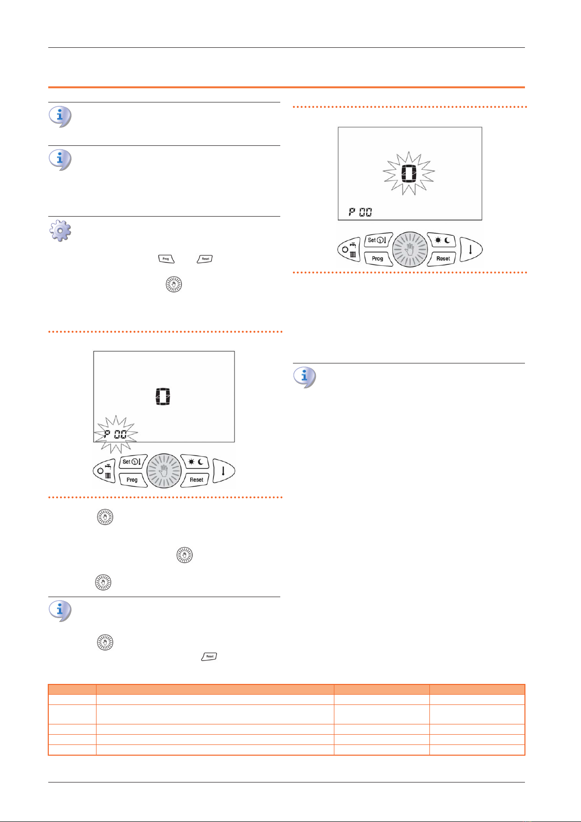
3. To conrm access, press the key. The display shows the
parameter number instead of the time and the value asso-
ciated with the parameter instead of the temperature. The
parameter number ashes (Figure 4.1
p.7
).
Figure4.1Selection of the parameter to be modied
4. Turn the knob to select the parameter number to be
displayed. The display shows the value associated with the
parameter.
5. To change the value press the knob: the value associ-
ated with the parameter starts ashing (Figure 4.2
p.7
).
6. Turn the knob to change the displayed value.
If no key is pressed for a period of 30 seconds, the change
made is aborted and normal operation is restored.
7. Press the key to save the value.
8. To exit the conguration mode, press .
Figure4.2Changing the selected value (ashing)
The editable parameters are as follows:
▶
P00 Room temperature probe correction
Value to add/subtract (-5.0 °C ÷ +5.0 °C) to the displayed
room temperature to compensate for any errors.
▶
P01 Trip temperature for the room antifreeze function
Trip temperature for the room antifreeze function (0,1 ÷
10,0 °C).
Setting parameter P01 to 0,0 disables the room anti-
freeze function.
▶
P02 Thermal dierential (OFF)
Value to be added to the set room setpoint that deter-
mines the end of the heating request.
Example:
Tsetpoint = 20,0 °C
P02 = 0,5 °C
Tsetpoint + P02 = 20,0 + 0.5 = 20,5 °C
The heat demand ends when the Troom is greater than
20,5 °C.
▶
P03 Thermal dierential (ON)
Value to be subtracted from the set room setpoint that
determines the start of the heating request.
Example:
Tsetpoint = 20,0 °C
P03 = 0,5 °C
Tsetpoint - P03 = 20,0 - 0,5 = 19,5 °C
The heat demand starts when the Troom is less than 19,5
°C.
▶
P04 Thermoregulation type
0 = On / O
1 = Modulating on room temperature probe
2 = Modulating on outdoor temperature probe
3 = Modulating on outdoor and room temperature
probes
4 = Disabled
Table4.1Operating parameters
Parameter Description Value Default
P00 Room temperature probe correction -5 / +5 °C 0 °C
P01 Trip temperature for the room antifreeze function 0,1 / 10 °C
0,0 °C = OFF 5 °C
P02 Thermal dierential OFF 0,0 / +1 °C + 0,3 °C
P03 Thermal dierential ON -1,0 / 0,1 °C - 0,3 °C
P04 Thermoregulation type 0 - 4 0

8
5 DISABLING THERMOREGULATION
If the remote control is installed in an environment where the
temperature is not to be controlled (technical room, oce, other
room than the boiler heated one), it is possible to disable the
request for heat from the remote control itself. To do this, set pa-
rameter P04 = 4 (see Paragraph 4
p. 7
). Instead of the room
temperature, the display shows dIS (Figure 5.1
p.8
).
Figure5.1Room temperature control from remote control: disabled
6 CONFIGURATION OF BOILER-RELATED PARAMETERS (TRANSPARENT
PARAMETERS - TSP)
This Paragraph is reserved exclusively for the author-
ised Robur Technical Assistance Centre.
The remote control does not know the meaning of the items
it displays but simply acts as a graphical interface to the boiler
board.
The number of parameters to be set is transmitted via Open-
Therm protocol.
How to congure transparent parameters (TSP)
1. Set the remote control to the OFF mode.
2. Press and hold down the and keys for longer
than 10 seconds.The display will show the ashing word tSP.
3. Release the and keys and, to enable the congu-
ration, press the knob within 10 seconds.
4. The display shows the ashing number of the parame-
ter instead of the time and the value associated with the
parameter instead of the temperature.
5. Turn the knob to select the parameter number to be
displayed. The temperature display shows the values asso-
ciated with the various parameters. Once the desired pa-
rameter has been selected, press the knob again: the
parameter number stops ashing and the value associated
with the parameter starts ashing to indicate that the value
can be changed.
6. Turn the knob to change the displayed value. To save
the value, press the knob again.
If no key is pressed for a period of 10 seconds, the change
made is aborted and normal operation is restored.
7. To exit the conguration mode before the timer expires,
press the key.
7 OPERATION MODE SELECTION
Depending on the boiler to which it is connected, some
of the operating modes described may not be available.
The operating mode of the boiler is selected by pressing the
key several times.The available operating modes are those
shown in Table 7.1
p.8
.
Table7.1Identication icon of the selected state
Selected status Identication icon
OFF
summer disabled
heating disabled
heating only
▶
OFF: all boiler operation requests are disabled (Figure
7.1
p.9
).

Installation and operation manual – remote control 9
Figure7.1Operating status OFF
▶
heating only: only operation in heating mode is enabled for
the production of hot water to the internal modules.
In this mode the boiler will produce hot water at the set
temperature, modulating the heat output as the set-
point temperature approaches.
8 CLOCK AND TEMPERATURE SETTING
The setting of the clock and of the temperature setpoints of
the remote control and of the boiler is done by pressing the
key several times according to the menu shown in Table
8.1
p.9
.
Table8.1Identication icon of the selected state
Selected status Identication icon
clock
day temperature
night temperature
The value of the item is displayed in the lower-left corner,
instead of the time, together with the ashing of its iden-
tication icon. To end the setting operation, press the
key repeatedly until all the identication icons are
o.
8.1 CLOCK SETTING
1. Press the key: the time ashes (Figure 8.1
p.9
).
Figure8.1Hour setting
2. Turn the knob to set the desired value.
3. Press the knob to conrm the value entered. The
hour stops ashing and the minutes start ashing (Figure
8.2
p.9
).
Figure8.2Minutes setting
4. Turn the knob to set the desired value.
5. Press the knob to conrm the value entered. The min-
utes stop ashing and the day of the week starts ashing
(Figure 8.3
p.9
).
Figure8.3Day setting

10
6. Turn the knob to set the desired value.
7. Press the knob to conrm the value entered. The day
stops ashing and the icon disappears.
8.2 DAY ROOM TEMPERATURE SETTING
1. Press the key until the icon starts ashing (Figure
8.4
p.10
).
2. Turn the knob to set the desired value.
Figure8.4Day room temperature setting
8.3 NIGHT ROOM TEMPERATURE SETTING
1. Press the key until the icon starts ashing (Figure
8.5
p.10
).
2. Turn the knob to set the desired value.
Figure8.5Night room temperature setting
8.4 HEATING TEMPERATURE SETTING
1. Press the key until the icon starts ashing (Figure
8.6
p.10
).
2. Turn the knob to set the desired value.
Figure8.6Heating temperature setting
This temperature value for models of the Caldaria family
must be set to 80 °C. The change of this value will be
operative on the boiler until the remote control is con-
nected to it.
8.5 DHW TEMPERATURE SETTING NOT
APPLICABLE
8.6 OUTDOOR PROBE KD VALUE SETTING
NOT APPLICABLE
9 SETTING MANUAL/AUTOMATIC OPERATION
The remote control provides the possibility to manage the room
temperature in two ways: manual or automatic.
▶
In manual mode, the user selects the desired room temper-
ature, which will be maintained until a new change is made.
▶
In automatic mode, the room temperature setpoint is de-
termined by the time and day corresponding to the weekly
program set.
9.1 MANUAL OPERATION
1. Press the key until the icon appears. The display
shows the set temperature value ashing (Figure 9.1
p.11
).
2. Turn the knob to set the desired temperature.
3. After the 30-second time delay, the central display returns to
the current temperature.

Installation and operation manual – remote control 11
4. The set temperature can be changed at any time by turning
the knob.
5. You can display the set temperature by pressing the
key.
Figure9.1Manual operation: setting the desired temperature
9.2 AUTOMATIC OPERATION
1. Press the key until the heating clock face is displayed.
2. The or icon is lit to indicate which temperature lev-
el is currently set.
Figure9.2Heating clock display and night temperature icon
10 WEEKLY HEATING PROGRAM
The room temperature can be set to two independent levels:
day ( ) and night ( ) whose distribution throughout the day
is managed by the weekly heating program.
The remote control contains a standard room temperature man-
agement program that can be viewed and freely modied by the
user.
The display/modication mode of the heating program is acti-
vated by pressing the key and is identied by the activa-
tion of the PROG icon at the top left of the display.
Table10.1Identication icon of the heating program operation
Function Identication icon
heating program display PROG not ashing
change heating program PROG ashing
Once the changes have been made, press the key
again to exit the programming mode.
10.1 HEATING PROGRAM DISPLAY
1. Press the key.
2. The display shows the PROG and icons to indicate the
rst day of the week. The / and time switch icons
are on or o at the day/night level associated
with the displayed time (Figure 10.1
p.11
).
3. Turn the knob to scroll through the times of the day and
switch between the days.
Figure10.1Heating program selection
10.2 CHANGE HEATING PROGRAM
1. Press the key.
2. The display shows the PROG and icons to indicate the
rst day of the week. The / and time switch icons
are on or o at the day/night level associated
with the displayed time (Figure 10.1
p.11
).
3. Press the key to switch to the program editing mode:
the PROG icon and the day of the week ash.
4. Turn the knob to select the desired day.
5. Press the knob to conrm the selected day and move
to the time. The day of the week stops ashing and the time
starts ashing.
6. Turn the knob to select the desired time.

12
7. Press the key to change the day/night temperature lev-
el associated with the current time.
8. Turn the knob until the time you want to keep the cur-
rent level.
9. Press the button to change the level and proceed in
the same way for the other changes.
10. To change the day, repeat operations from step 3.
11. To exit the heating programming, press the key.
11 TEMPORARY CHANGE OFTHE ROOM SETPOINT
In the case of automatic operation, the room setpoint for the day
() or night ( ) can be temporarily raised or lowered. The
change is valid until the next day/night change, after which it is
lost.
1. Press the key to display the set room temperature.
2. Turn the knob to select the value. The icon will
ash for the duration of the change to indicate the setpoint
change made (Figure 11.1
p.12
).
3. To deactivate the function before it expires, press the
key.
Figure11.1Temporary change of the room setpoint
12 FAULT SIGNALS
Any faults are displayed by the remote control with the Exx code
ashing.
For more details about the fault refer to the
Installation, use and maintenance manual of the specic
Caldaria appliance used.
The faults can be of two types: resettable by the user and not
resettable.
12.1 RESETTABLE FAULTS
These errors are identied by the ashing icon and can be
reset by pressing the key.
If there are no more available attempts to reset the fault,
the icon is lit with no ashing. In this case, please
contact the TAC.
Figure12.1Resettable fault
12.2 NON RESETTABLE FAULTS
These faults are identied by the icon and cannot be reset
by the user but require the intervention of the TAC.
Also part of this error group is the code E06 (remote control
room temperature probe fault) (Figure 12.2
p.13
).

Installation and operation manual – remote control 13
Figure12.2Non resettable fault
13 TEMPERATURE VALUES DISPLAY
By pressing the key several times, the remote control is able
to display the values of the items shown in Table 13.1
p.13
.
Table13.1Identication icon of the selected item
Selected item Identication icon
set room temperature
DHW probe temperature*
delivery probe temperature
outdoor temperature*
* Not applicable to this model
▶
Set room temperature display: corresponds to the set tem-
perature for the active temperature level (day/night/manu-
al) (Figure 13.1
p.13
).
Figure13.1Set room temperature display
▶
Delivery probe temperature display: corresponds to the
temperature read by the delivery water probe in the boiler
(Figure 13.2
p.13
).
Figure13.2Delivery water probe temperature display
14 ROOM ANTIFREEZE FUNCTION
The remote control is equipped with the room antifreeze func-
tion (which can be excluded if necessary) which, regardless of
the selected operating mode, controls the boiler activation
when the temperature detected by the room probe is lower
than the value set in parameter P01, thus providing protection
of the system from the danger of freezing.

14
15 ERROR CODES
For information about the error codes that may appear
on the remote control display during operation, refer to the Installation, use and maintenance manual of the
specic Caldaria appliance used.
16 RESTORE DEFAULT VALUES
You can reset the settings of the remote control to their factory
settings.
The default values of the temperatures are:
▶
Day temperature: 20 °C
▶
Night temperature: 16 °C
▶
Manual temperature: 20 °C
The factory-set weekly heating program is shown in Table
16.1
p.14
.
Table16.1Weekly heating program
Days of the week Night Day
Monday - Friday
00.00 ÷ 06.00
08.00 ÷ 16.30
22.00 ÷ 00.00
06.00 ÷ 08.00
16.30 ÷ 22.00
Saturday - Sunday 00.00 ÷ 07.00
23.00 ÷ 00.00 07.00 ÷ 23.00
How to reset default values
1. Set the remote control to the OFF mode.
2. Press and hold down the and keys for longer
than 5 s.
3. The operation success will be conrmed by the word dEF on
the display (Figure 13.2
p.13
).
Figure16.1Restore default values
17 COMPLETE RESET
Faults or other technical reasons may require a total reset of the
remote control.
How to perform a complete reset
1. Using a screwdriver, slide the remote control interface out of
the rear xing box, applying slight pressure on the two lower
tabs (Figure 17.1
p.14
).
2. Press button 1 (Figure 17.2
p.15
).
3. After a complete reset, the time and day of the week must be
set again (Paragraph 8.1
p.9
).
Figure17.1Complete reset

Installation and operation manual – remote control 15
Figure17.2Complete reset
18 TECHNICAL SPECIFICATIONS
Table18.1Technical specications
Description Value
Power supply via communication bus
Number of temperature levels 2 (day / night)
Day temperature setting range 5 ÷ 30 °C
Night temperature setting range 5 ÷ 30 °C
Manual temperature setting range 5 ÷ 30 °C
Setting range of the thermal dierential (OFF) 0,0 ÷ 1,0 °C
Setting range of the thermal dierential (ON) ‐1,0 ÷ ‐0,1 °C
Correct operating range of the room temperature probe ‐40 ÷ 50 °C
Temperature resolution 0,1 °C
Room temperature range for antifreeze function (0,0 °C = OFF) 0,1 ÷ 10,0 °C
Stop temperature for the room antifreeze function set value + 0,6 °C
Heating time programming resolution 30 minutes
Maximum number of daily on/o 48
Number of standard heating programs 1
Number of standard DHW programs 1
Backup battery life in case of power failure 1 hour
Operating temperature range 0 ÷ 50 °C
Storage temperature ‐10 ÷ 50 °C
Dimensions (WxHxD) 118×85×30 mm
Maximum boiler connection cable length 50 m
Boiler connection cables section 0,5 ÷ 1,5 mm²
19 PRODUCT FICHE
Table19.1Commission delegated regulation (EU) n. 811/2013 - Temperature controls
Supplier Model Class of the temperature control Contribution of the temperature control to seasonal space heating energy eciency in %,
rounded to one decimal place
Robur OCDS006 V 0,03

Code: D-LBR718EN 02/08/2019
Robur S.p.A.
advanced technologies
for climate conditioning
via Parigi 4/6
24040 Verdellino/Zingonia (BG) Italy
+39 035 888111 - F +39 035 884165
www.robur.it robur@robur.it
Robur is dedicated to dynamic progression
in research, development and promotion
of safe, environmentally-friendly, energy-eciency products,
through the commitment and caring
of its employees and partners.
Revision: A 19 MED SDC 012
Robur mission
Other manuals for OCDS006
1
Table of contents
Other Robur Remote Control manuals