DESIGN
FEATURES
45 7 8
11
12 7 8 14 15
T1000-4ad
,l_-"~-ll..n...----------+--+.....lt-------+----J~r-------_--!l--'L~~-
I
6910 13 10 9
I,
Power
LED
(Top of unit -
Not
Shown) -This
Blue
LED
illuminates when the unit
is
turned on,
2.
Thermal
LED
(Top of unit -
Not
Shown) -This Red
LED
illuminates
if
the amplifier internal components
become
too
hot
and engage the thermal protection. The amplifier
will
shut down
to
cool
if
this occurs.
3.
Protect
LED
(Top of unit -
Not
Shown) -This Yellow
LED
illuminates
if
a
short
circuit
or
too
low
of
an
impedance
is
detected
at
the speaker connections. The shorted channel(s)
will
shut down automatically
if
this occurs.
All
other
channels
will
operate
normally.
4.
Cast
Aluminum Heatsink -The cast aluminum heatsink
of
the Power amplifier dissipates heat generated
by
the
amplifier's circuitry.
5.
Speaker Terminals -The heavy duty, nickel-plated clamp wire connectors
(+
and
-)
will
accept wire sizes
from 8
AWG
to
18
AWG.
6.
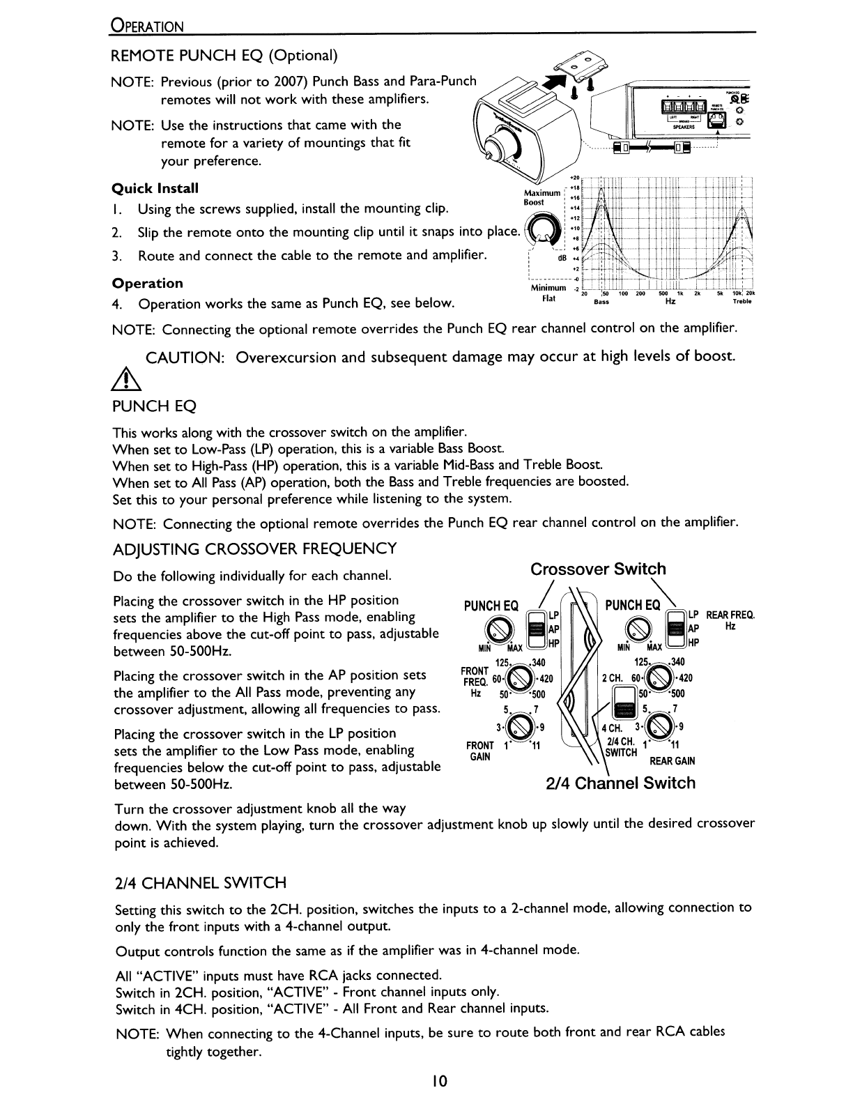
Remote Punch EQ (Optional Controller) -The Remote Punch
EQ
connection
is
made with a
RJ-45
cable
and can be installed
in
avariety
of
ways for easy control access. The control
is
used
to
boost
low and/or
high
frequency information
to
overcome road noise.
The
remote
overrides the Punch EQ
rear
channel
control
on
the amplifier when connected.
NOTE: Previous (prior
to
2007) Punch Bass and Para-Punch
remotes
will
not
work
with this amplifier.
7.
Punch EQ - A Gyrator based Punch
EQ
that
eliminates frequency shift with boost. This works along with
the
crossover switch
on
the amplifier.
When
set
to
Low-Pass
(LP)
operation, this
is
avariable
Bass
Boost.
When
set
to
High-Pass (HP) operation, this
is
avariable Mid-Bass and Treble Boost.
When
set
to
All
Pass
(AP)
operation, both the
Bass
and Treble frequencies
are
boosted.
8.
Crossover
Switch -Selectable switch for High-Pass (HP),
All
Pass
(AP),
or
Low-Pass
(LP)
operation.
9.
Variable
Crossover
-
Is
abuilt-in 24dB/octave
Butterworth
filter with a
crossover
point variable from
50Hz
to
500Hz.
10.
Gain Control -The input
gain
control
is
preset
to
match the
output
of most source units.
It
can be
adjusted
to
match
output
levels from avariety
of
source units.
I
I.
RCA Input Jacks -The industry standard RCA jacks provide
an
easy connection for
signal
level
input.
They
are
nickel-plated
to
resist the
signal
degradation caused
by
corrosion.
12.
RCA Pass-Thru Jacks -This Pass-Thru provides aconvenient source for
daisy-chaining
an
additional amplifier without running
an
extra
set
of
RCA cables from the front of
the vehicle
to
the rear amplifier location.
13.
2/4 Channel Switch -Setting this switch
to
the
2CH. position, switches
the
inputs
to
a2-channel
mode, allowing connection
to
only
the
front
inputs with a4-channel output.
14.
REM
Terminal -The heavy duty, nickel-plated captive
c-c1amp
wire connector
will
accept wire sizes from
12
A
WG
to
24 A
WG.
This terminal
is
used
to
remotely turn-on and turn-off the amplifier when +
12V
DC
is
applied.
15.
Power Terminals -The
power
and ground
are
nickel-plated captive
c-c1amp
wire connectors and
will
accommodate up
to
4 A
WG
wire.
4