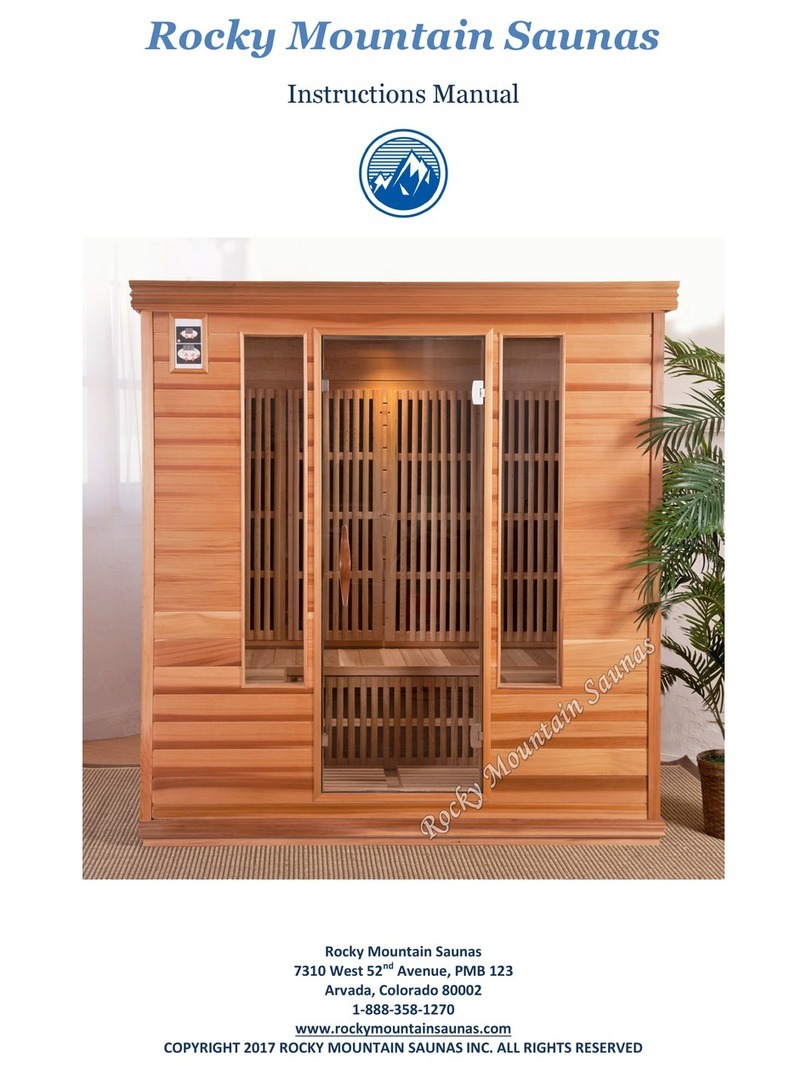
Rocky Mountain Saunas Badger User manual

2
Table of Contents
INSTALLATION
Page(s)
Electrical Requirements 3
General Assembly Guidelines 4
Delivery & Unpacking Your Sauna 5
Badger, Colorado, and Durango Assembly Instructions 6 - 14
Rio Grande Assembly Instructions 15 - 25
Big Bear Assembly Instructions 26 - 37
Door Handle Installation 38 - 40
HOW TO USE
Pages(s)
Control Panel Operating Instructions 41 –43
Ionizer Instructions 44
Frequently Asked Questions 45
Disclaimers & Safety Precautions 46
Warranty and Return Policy Information 46
Safety Certifications 47

3
Electrical Requirements
Information for All Sauna Models
** The outlet in which the sauna is plugged into must be a Dedicated Circuit while in use. A Dedicated Circuit is
intended for use with a single appliance and generally has its own circuit breaker in the sauna location’s electrical box.
** Any electrical changes or required upgrades must be made by a qualified, licensed electrician. Failure to comply may
result in safety issues and voiding of the sauna warranty.
** The power cord for the sauna is located in the roof cap and measures 9 feet in length. It is recommended that the
location of the outlet be accessible without moving the sauna.
** The use of an extension cord is not recommended as the sauna may not operate as designed.
Badger and Colorado Models
Normally, no electrical modification is required to be able to use these models in a home. Standard household outlets
are either 110V/15 Amp with 12/2-gauge wire, or 110V/20 Amp with 12/2-gauge wire. Either circuit will accommodate
these models. The required outlet is a NEMA 5-15R.
110 Volts/15 Amp dedicated circuit/outlet
NEMA 5-15R (required)
Durango and Rio Grande Models
An upgrade to the circuitry is required for these two models. For proper operation a 110v/20amp circuit with 12/2-
gauge wire is necessary. The required outlet is NEMA 5-20R.
110 Volts/20 Amp dedicated circuit/outlet
NEMA 5-20R (required)
Big Bear Model
An upgrade to the circuitry is required for this model. For proper operation, a 220V/20 Amp circuit with 12/2-gauge
wire is necessary. The required outlet is a NEMA 6-20R.
220 Volts/20 Amp dedicated circuit/outlet
NEMA 6-20R (required)

4
General Assembly Guidelines
TOOLS NEEDED
#2 Phillips Head Screwdriver
Small Step Ladder
Metal Band Cutters or Pliers
Exacto Knife or Scissors
MOVING THE SAUNA AFTER ASSEMBLY
If the sauna needs to be moved after assembly, perhaps into an alcove or confined space, Rocky Mountain
Saunas strongly recommends the use of furniture sliders. These can be found at a local hardware store such
as Lowe’s or Home Depot. Place the furniture sliders under the perimeter corners of the Base Platform of the
sauna, prior to beginning assembly.
Important note:
When moving the assembled sauna:
1. Do not push on the cabin walls as this can cause damage to the sauna cabin
2. Always push on the base platform to move the sauna
3. After sauna has been moved to desired location, the sliders can be left in place to ease any future
movement needed
GENERAL
All panels are labeled with white stickers. These can be left on the panels after assembly. That way if the
sauna is ever broken down for movement there is no confusion come re-assembly.
Please follow instructions carefully. Should you have any questions, please do not hesitate to contact Rocky

5
Delivery & Unpacking Your Sauna
When the sauna arrives at its delivery location, it will be packaged in three (3) separate boxes, which are
banded to a pallet. Depending on the model of the sauna, the unit may also be half crated.
Badger/Colorado Durango/Rio Grande/Big Bear
Break down the pallet at the delivery point and lay each box flat with the labeling facing up.
The boxes are labeled numerically 1, 2 and 3 to indicate the order in which to open the boxes. Due to the
weight of the boxes, open all boxes first and carry each individual panel to the desired installation location.
Do not try to carry a full box. Stage the sauna pieces prior to beginning installation to help aid in the ease of
the installation.

6
Badger, Colorado, and Durango Assembly
Instructions
Floor Base
Lay the Floor Base in the area close to where the sauna is going to be permanently located. It is suggested to
place furniture sliders under the base for ease of movement. Sliders can be found at any local hardware store.
The positioning of the Floor Base should be such that the floor heater is facing outward, or closest to where
the Front Wall will be installed. A label indicating the front of the Floor Base can be found by the heater panel
to help aide in the proper positioning of the Floor Base.
The Floor Base includes trim pieces on all four sides that serve as guides for the installation of the four walls as
well as the Bench Heater Panel.

7
Back Wall
Starting with the Back Wall, place the Back Wall on the Floor Base so the interior side of the wall sits flush with
the floor trim. One person will need to balance the wall to hold it in place.
Front Wall
The glass door on the Front Wall will be secured to keep the door from opening or closing during installation.
Removal of the glass door support should be completed prior to the Right Wall being installed.
To ensure the glass door does not open or shut slightly, carry this wall at a slight angle with the bottom of the
wall slightly out compared to the top. Place the interior of the Front Wall on the Floor Base so it sits flush with
the floor trim. One person will need to balance the Front Wall to hold it in place.

8
Left Side Wall
Using the floor trim as a guide, place the Left Side Wall on the Floor Base. If needed, gently tap the Left Side
Wall in to ensure a snug fit.
The Left Side Wall includes trim pieces on both sides that will wrap around the Back and Front Walls.
Left Side Wall Bolt Installation
While one person supports the Front and Back Walls, a second person inserts the installation bolts supplied in
the accessories box into the predrilled holes on the Left Side Wall connecting it to the Front and Back Walls.
No certain order of installing the bolts is required. At this time, finger tighten the bolts. A screwdriver may be
used to tighten the bolts slightly but leave some slack to facilitate in the completion of the installation. A final
tightening of the installation bolts will be performed later. If needed, adjust the Front and Back Walls slightly,
in order to get the predrilled holes to align correctly.

9
Bench Heater Panel
Install the Bench Heater Panel by bringing it through the opening on the right side of the sauna.
A label is located on the top of the Bench Heater Panel indicating which side needs to be placed facing up.
Place the Bench Heater Panel between the guides found on each side of the bottom of the Floor Base with the
heater panel facing the door. Lastly, ensure the heater cord is placed behind the Bench Heater Panel.

10
Under Bench Connections
Two power cords are located behind the Bench Heater Panel: one for the floor heater and one for the bench
heater. Plug each cord into the receptacle on the Back Wall.
Bench Seat
Locate the predrilled hole in the Bench Seat. This hole indicates which side of the Bench Seat to place against
the interior of the Back Wall.
Bring the Bench Seat in through the right side of the sauna, then lay horizontal for installation. Wait to install
the anchoring screw into the bench seat until later.

11
Right Side Wall
The Right Side Wall includes trim pieces on both ends that wrap around the Back and Front Walls. Make any
adjustments needed to the Front and Back Walls to allow the trim to wrap around the walls appropriately.
Insert the remaining installation bolts into the predrilled holes to connect the Right Side Wall with the Front
and Back Walls. Again, only finger tighten the bolts. If needed, use a screwdriver to tighten the bolts but do
not tighten completely.
Roof Cap
The Roof Cap has five predrilled holes to pass through the wiring protruding from the top of the Front, Back
and Side Walls. Two holes are in the front of the Roof Cap, one hole on each side, and one in back of the Roof
Cap. The curved end of the Roof Cap is the front.

12
Carefully place the Roof Cap on the top of the sauna. It does not need to sit flush with the walls at this time
since the power cables need to be fed through the predrilled holes.
On the left-hand side of the Front Wall, above the Control Panel are six cables. Feed all six cables through the
hole in the Roof Cap.
Feed the remaining black heater plugs through the pre-drilled holes on the Roof Cap located on the right front,
Right Side Wall towards the back of the wall, the middle back of the Roof Cap and the Left Side Wall towards
the back of the wall.
Once all the cables have been threaded through the Roof Cap holes, place the Roof Cap securely onto the
walls of the sauna.

13
Final Electrical Connections
To make the electrical connections on the top of the Roof Cap a small step stool or a ladder will be needed.
Starting with the cables above the Control Panel, connect the six cables to their corresponding connections on
the top of sauna.
Continue to make the additional power cord connections around the top of the sauna.
Dust Cover
Install the Cover provided onto the Roof Cap to keep the Roof Cap free of dust. Feed the power cord and the
radio antenna through the holes provided to allow the cover to sit flush on the Roof Cap. If desired, screws
are provided in the Accessories box to attach the dust cover to the Roof Cap. Attachment is not required.
Installation Bolt Tightening
Using a screwdriver, perform a final tightening of the installation bolts on the Left and Right Side Walls. If the
installation bolts do not tighten easily, or interior trim pieces do not align correctly, adjust any walls as needed
until all walls fit flush with one another. DO NOT over-tighten the bolts as doing so can cause damage to the
wood cabin.

14
Secure the Bench Seat
Using the 2.25 inch bench screw provided in the accessories box, secure the Bench Seat to the bench seat
support.
Door Handle Installation
For Door Handle installation instructions, see Page 38.
Accessories Installation
Installation of the optional accessories can be completed at this time. The accessories can be placed wherever
desired, or not used at all.
Operational Check
Perform an Operational Check by turning the sauna on and setting the temperature for 150°F for 60 minutes.
During the first hour of operation the sauna should reach approximately 135°F. Test all lights for proper
operation as well.

15
Rio Grande Assembly Instructions
Floor Base
Starting with the Floor Base, lay it in the area close to where the sauna is going to be permanently located. It
is suggested to place furniture sliders under the base for ease of movement. Sliders can be found at any local
hardware store.
The positioning of the Floor Base should be such that the floor heater is facing outward, or closest to where
the Front Wall will be installed. A label indicating the front of the Floor Base can be found by the heater panel
to help aide in the proper positioning of the Floor Base.
The Floor Base includes trim pieces on all five sides that serve as guides for the installation of the five walls as
well as the bench heater panels.

16
Middle Front Wall
The glass door on the Middle Front Wall will be secured to keep the door from opening or closing during
installation. The removal of the glass door support should be completed prior to the Right Back Wall being
installed. To ensure the glass door does not open or shut slightly during installation, carry this wall at a slight
angle with the bottom of the wall slightly out compared to the top. Place the interior of the Middle Front Wall
on the Floor Base so it sits flush with the floor trim. One person will need to balance the Front Wall to hold it
in place.
The Middle Front Wall includes three metal guides on each side to accommodate the addition of the Left and
Right Front Walls.

17
Left Front Wall
Lift the Left Front Wall slightly higher than the Floor Base to attach it via the metal guides to the Middle Front
Wall. One person will need to balance the Left Front Wall to hold it in place.
Left Back Wall
The Left Back Wall includes trim that will wrap around the Left Front Wall. To ensure the proper placement of
the Left Back Wall trim, install the Left Back Wall onto the Floor Base by slightly sliding it in from the front of
the Floor Base towards the back of the Floor Base. Line up the Left Back Wall trim with the trim on the Floor
Base as well.
Left Back Wall Bolt Installation
While one person supports the Middle and Left Front Walls, a second person inserts the installation bolts
supplied in the accessories box into the predrilled holes on the Left Back Wall connecting it to the Left Front
Wall. No certain order of installing the bolts is required. At this time, finger tighten the bolts. A screwdriver
may be used to tighten the bolts slightly, but leave some slack to facilitate in the completion of the
installation. A final tightening of the installation bolts will be performed later. If needed, adjust the Front and
Back Walls slightly, in order to get the predrilled holes to align correctly.

18
Left Bench Heater Panel
Install the Left Bench Heater Panel by bringing it through the opening on the back side of the sauna. A label is
located on the top of the left bench heater panel indicating which side needs to be placed facing up.
Place the Bench Heater Panel between the guides found on the Floor Base with the heater panel facing
forward towards the door.
Lastly, ensure the heater cord is placed behind the bench heater panel.

19
Right Bench Heater Panel
Place the Right Bench Heater Panel onto the Floor Base by first lining it up with the trim guides on the Floor
Base trim. Lastly, ensure the heater cord is placed behind the bench heater panel.
Under Bench Connections
Two power cords are located behind the Left Bench Heater Panel: one for the floor heater and one for the
bench heater. Plug each cord into the receptacle on the Left Back Wall.
Right Front Wall
Lift the Right Front Wall slightly higher than the Floor Base to simultaneously attach it to Middle Front Wall via
the metal guides, as well as line up the wall with the Floor Base trim.

20
Right Back Wall
The Right Back Wall includes trim that will wrap around the Right Front Wall and the Left Back Wall. Any
adjustments that need to be made to align the walls and ensure proper placement of the outside wall trim can
be done at this time.
Right Back Wall Bolt Installation
Insert the installation bolts supplied in the accessories box into the predrilled holes on the Right Back Wall to
make the final bolt connections for the unit. No certain order of installing the bolts is required. At this time,
finger tighten the bolts. A screwdriver may be used to tighten the bolts slightly, but leave some slack to
facilitate in the completion of the installation. A final tightening of the installation bolts will be performed
later. If needed, adjust the Right Front and Left Back Walls slightly, in order to get the predrilled holes to align
correctly.
Under Bench Connections
One power cord is located behind the Right Bench Heater Panel. Plug the cord into the receptacle on the
Right Back Wall.
Other manuals for Badger
1
This manual suits for next models
4
Table of contents
Other Rocky Mountain Saunas Plumbing Product manuals
Popular Plumbing Product manuals by other brands

American Standard
American Standard Jasmine Amarilis 3630 SERIES installation instructions

Master
Master MAS-I273 user manual

Omnires
Omnires Y1238/KROGL Installation and Maintenance

Rubi
Rubi VERTIGO RVT22D Installation

Belvedere
Belvedere 8400 BACKWASH SHAMPOO BOWL quick start guide

Sanela
Sanela SLU 09PTB Instructions for use